EP1489680B1 - Système d'antenne pour vitre de véhicule - Google Patents
Système d'antenne pour vitre de véhicule Download PDFInfo
- Publication number
- EP1489680B1 EP1489680B1 EP04253668A EP04253668A EP1489680B1 EP 1489680 B1 EP1489680 B1 EP 1489680B1 EP 04253668 A EP04253668 A EP 04253668A EP 04253668 A EP04253668 A EP 04253668A EP 1489680 B1 EP1489680 B1 EP 1489680B1
- Authority
- EP
- European Patent Office
- Prior art keywords
- electrically conductive
- antenna
- antenna system
- glass
- printed line
- Prior art date
- Legal status (The legal status is an assumption and is not a legal conclusion. Google has not performed a legal analysis and makes no representation as to the accuracy of the status listed.)
- Expired - Lifetime
Links
- 239000011521 glass Substances 0.000 title claims abstract description 41
- 239000004020 conductor Substances 0.000 claims abstract description 13
- 239000005357 flat glass Substances 0.000 claims description 18
- 229910052751 metal Inorganic materials 0.000 claims description 14
- 239000002184 metal Substances 0.000 claims description 14
- 238000010438 heat treatment Methods 0.000 claims description 8
- 230000002093 peripheral effect Effects 0.000 claims description 2
- BQCADISMDOOEFD-UHFFFAOYSA-N Silver Chemical compound [Ag] BQCADISMDOOEFD-UHFFFAOYSA-N 0.000 abstract description 33
- 229910052709 silver Inorganic materials 0.000 abstract description 33
- 239000004332 silver Substances 0.000 abstract description 33
- 230000035945 sensitivity Effects 0.000 description 11
- 239000003990 capacitor Substances 0.000 description 5
- 239000005340 laminated glass Substances 0.000 description 5
- 238000004904 shortening Methods 0.000 description 4
- 230000001105 regulatory effect Effects 0.000 description 3
- 239000000758 substrate Substances 0.000 description 3
- 239000002131 composite material Substances 0.000 description 1
- 230000000694 effects Effects 0.000 description 1
- 238000004519 manufacturing process Methods 0.000 description 1
- 239000000843 powder Substances 0.000 description 1
- 230000000644 propagated effect Effects 0.000 description 1
- 238000004088 simulation Methods 0.000 description 1
- 238000005476 soldering Methods 0.000 description 1
Images

Classifications
-
- H—ELECTRICITY
- H01—ELECTRIC ELEMENTS
- H01Q—ANTENNAS, i.e. RADIO AERIALS
- H01Q13/00—Waveguide horns or mouths; Slot antennas; Leaky-waveguide antennas; Equivalent structures causing radiation along the transmission path of a guided wave
- H01Q13/10—Resonant slot antennas
- H01Q13/16—Folded slot antennas
-
- H—ELECTRICITY
- H01—ELECTRIC ELEMENTS
- H01Q—ANTENNAS, i.e. RADIO AERIALS
- H01Q1/00—Details of, or arrangements associated with, antennas
- H01Q1/12—Supports; Mounting means
- H01Q1/1271—Supports; Mounting means for mounting on windscreens
- H01Q1/1278—Supports; Mounting means for mounting on windscreens in association with heating wires or layers
-
- H—ELECTRICITY
- H01—ELECTRIC ELEMENTS
- H01Q—ANTENNAS, i.e. RADIO AERIALS
- H01Q5/00—Arrangements for simultaneous operation of antennas on two or more different wavebands, e.g. dual-band or multi-band arrangements
- H01Q5/30—Arrangements for providing operation on different wavebands
- H01Q5/307—Individual or coupled radiating elements, each element being fed in an unspecified way
- H01Q5/342—Individual or coupled radiating elements, each element being fed in an unspecified way for different propagation modes
- H01Q5/357—Individual or coupled radiating elements, each element being fed in an unspecified way for different propagation modes using a single feed point
-
- H—ELECTRICITY
- H01—ELECTRIC ELEMENTS
- H01Q—ANTENNAS, i.e. RADIO AERIALS
- H01Q5/00—Arrangements for simultaneous operation of antennas on two or more different wavebands, e.g. dual-band or multi-band arrangements
- H01Q5/40—Imbricated or interleaved structures; Combined or electromagnetically coupled arrangements, e.g. comprising two or more non-connected fed radiating elements
Definitions
- the present invention generally relates to a glass antenna system for vehicles, particularly to a glass antenna system for receiving AM and FM broadcasts.
- a rod antenna has been provided as an antenna system for receiving AM and FM broadcasts.
- An antenna element of the rod antenna is protruded from the body of a vehicle, so that the antenna element has a tendency to be injured.
- a glass antenna system has been provided in which the pattern of electrically conductive lines of the paste including silver powders (referred to as silver printed lines) are printed on a window glass of a vehicle.
- an antenna pattern becomes complicated in order to realize a good sensitivity for FM band (76-90MHz) in the case that the antenna pattern is formed on a small window such as a side window, resulting in a bad appearance of the side window.
- a slot antenna has also provided which is formed in a space between an electrically conductive transparent film for reflecting sunlight provided on a glass window of a vehicle and a body of the vehicle.
- This kind of a slot antenna has been disclosed in Japanese Patent Publication Nos. 6-45817, 9-175166 and 2002-290145.
- An antenna disclosed in Japanese Patent Publication No. 6-45817 is a slot antenna formed on a windshield of a vehicle.
- the technical word "slot antenna” means an antenna comprising a rectangular opening having a fixed length and width in an electrically conductive plate. The slot antenna, therefore, has both ends in a rectangular opening independently of the shape of the opening.
- the slot antenna disclosed in the Japanese Patent Publication is structured by a complete loop-shaped opening, so that the slot antenna does not have both ends thereof. In this meaning, this slot antenna is a slot antenna in a broad sense.
- This slot antenna also has a complicated structure because an interface region is required to match the impedance of the slot antenna to that of a coaxial feeder.
- the antenna disclosed in Japanese Patent Publication No. 9-175166 has a composite structure consisting of a slot antenna and an antenna element provided in the slot antenna in order to receive a wide frequency band.
- a slot antenna for receiving FM and TV bands is disclosed in Japanese Patent Publication No. 2002-290145.
- This slot antenna is formed between an electrically conductive film and a body of a vehicle, and comprises two electrically conductive portion each for electrically connecting the electrically conductive film and the body of a vehicle to each other.
- the bands capable of receiving are limited to only FM and TV bands, and then AM band may not be received.
- a slot antenna is disclosed in DE 10146439 having the precharacterizing features of claim 1.
- a glass antenna system according to the present invention is structured in such a manner that the system functions both as a planar antenna for receiving AM band and as a slot antenna for receiving FM band.
- slot antenna herein means an antenna comprising an opening having a fixed length and width in an electrically conductive plate.
- opening is used herein to mean an opening which is formed in an electrically conductive plate by removing a part thereof.
- the slot antenna therefore, has both ends in an opening independently of the shape of the opening.
- a loop-shaped opening is formed between an electrically conductive portion and an electrically conductive printed line surrounding the electrically conductive portion.
- the opening may function as a slot antenna for receiving FM band.
- the electrically conductive printed line is to be connected in an alternating current (AC) manner to a metal part of a vehicle according to the definition of the word "slot antenna".
- AC alternating current
- the electrically conductive printed line is provided along the circumference of a window glass, the electrically conductive printed line is capacitively coupled to the metal part of a vehicle, and then is connected to the metal part of a vehicle in AC manner.
- the electrically conductive portion and electrically conductive printed line are connected to each other by an electrical connection to function as a planar antenna for receiving AM band.
- both the electrically conductive portion and the printed line should not be connected to the metal part of a vehicle in AC manner.
- the printed line is selected so that the impedance thereof is high in AC band, the printed line is not connected to the metal part of a vehicle in AC manner.
- a glass antenna system may function as a planar antenna and slot antenna to allow the reception of AM and FM bands.
- a glass antenna system for vehicles comprising:
- FIG. 1 there is shown an embodiment of a glass antenna system for vehicles according to the present invention.
- the antenna system is provided on a side window of a vehicle.
- a side glass 10 forming a side window is surrounded by a body 12 made of metal.
- An electrically conductive transparent film 14 for reflecting sunlight is provided on the side glass 10, and a silver printed line 16 having a wide width is formed on the peripheral portion of the electrically conductive transparent film 14.
- a loop-shaped silver printed line 18 is provide surrounding the film 14, which is capacitively coupled to the body 12. In this manner, an opening 20 is formed in a space between the silver printed line 18 and the electrically conductive film 14.
- An electrically shorted portion (i.e., a short stub) 24 is provided between the silver printed line 18 and the electrically conductive film 14.
- the silver printed line 18 and the electrically conductive film 14 are connected in a direct current (DC) manner.
- the purpose for providing the silver printed line 16 around the electrically conductive film 14 is to make the connection of a central conductor of a coaxial feeder thereto easy and to increase the sensitivity of a slot antenna by improving the flow of a current.
- the purpose for providing the loop-shaped silver printed line 18 is such that the line 18 functions together with the film 14 as a planar antenna for AM band, and the line 18 capacitively coupled to the body 12 to function the opening 20 between the film 14 and the line 18 as a slot antenna.
- the electrically conductive transparent film 14 may be formed directly on the surface of the side glass 10 or may be adhered to the side glass. In the case of a laminated glass, an electrically conductive film may be stacked in the laminated glass. It is preferable that a sheet resistance of the electrically conductive transparent film 14 is low (for example, lower than 4 ⁇ / ⁇ ).
- the glass antenna system shown in Fig.1 further comprises a coaxial feeder 22 for AM/FM.
- a central conductor of the feeder is soldered to the silver printed line 16 and the outer conductor to the body 12.
- connections of the central and outer conductors of the coaxial feeder 22 for AM/FM may be implemented by using terminals and connectors other than soldering.
- a film-shaped connector that is embedded in the laminated glass may be used for connecting the conductors to an electrically conductive transparent film provided in the laminated glass.
- the position of a terminal of the coaxial feeder 22 for AM/FM may be determined considering a design and a fabrication thereof.
- the electrically conductive film 14 and loop-shaped silver printed line 18 are used for AM antenna as a planar antenna, and the opening 20 electrically connected by means of the short stub 24 is used for FM antenna as a slot antenna.
- the body 12 and film 14 must be electrically connected in order to cause the opening 20 to function as a slot antenna, and then the short stub 24 is provided for this purpose.
- the position of the short stub 24 is selected in a following manner. That is, where the opening 20 forms a slot antenna for FM, the impedance of the slot antenna should be matched to that of the coaxial feeder 22 for AM/FM.
- the impedance of the slot antenna is determined by the length L thereof (i.e., the length of the opening 20), the width thereof (i.e., the width of the opening 20), the resistance of the silver printed line 18, and the position of the short stub 24 with respect to the feeding point of the coaxial feeder. While the position of short stub may be expected by simulation, it would be also determined by measuring the impedance of the slot antenna.
- the shortening factor relates to a propagation rate of a wave propagated through a dielectric substrate (a glass plate in this case), and is a ratio of the size of an antenna formed on the dielectric substrate with respect to the size of an antenna provided in a space rather than on the dielectric substrate. Therefore, it is preferable that the length of a slot antenna is determined so that the equation denoted above is satisfied.
- the distance between the loop-shaped silver printed line 18 and the body 12 is regulated such that the impedance is high for AM band and low for FM band.
- the capacitance between the line 18 and the body 12 is regulated in a range of 20-30pF for AM band.
- each of the silver printed lines 16 and 18 has preferably the width of 5mm or more from the point of view for the connection of a central conductor of the coaxing feeder 22 and the antenna efficiency.
- the electrically conductive transparent film 14 and the loop-shaped silver printed line 18 work as a planar antenna for receiving AM band, so that the area surrounded by the line 18 is determined in view of AM sensitivity.
- AM sensitivity is therefore determined by the area of a window glass.
- the area of a window glass of 0.14m 2 or more is preferable in view of AM sensitivity.
- the area of a window glass to which a glass antenna system according to the present invention is formed may be at least 0.14m 2 in the case that the antenna is resonated at 1/2 wavelength.
- a glass antenna system according to the present invention may be applied to a side window having a small area.
- the length L of the opening 20 is 1500mm.
- 1/2 wavelength is approximately 1.8m for the central frequency 83MHz of FM band (76-90MHz).
- the area of a window glass is 0.14m 2 and therefore satisfies the condition necessary for AM sensitivity. It will be understood that the glass antenna system having such dimensions may successfully receive both AM and FM bands. It is also understood that a glass antenna system according to the present invention may easily be implemented for a side window having an area of 0.15m 2 or more, for example.
- the electrically conductive transparent film 14 and the loop-shaped silver printed line 18 become a planar antenna and function as AM antenna.
- the loop-shaped silver printed line 18 is equivalent to the body in potential because the line 18 is capacitively coupled to the body in FM band.
- a slot antenna therefore, is formed between the film 14 and the line 18.
- a better sensitivity may be obtained because the short stub 24 is provided at the position where the impedance of the slot antenna is matched to that of the coaxial feeder 24.
- the area of the side glass is 0.15m 2 or more.
- the distance between the film 14 and the line 18 is regulated in a range of 10-30mm for an impedance for FM.
- the electrically conductive transparent film has been used.
- a ladder-shaped electrically conductive pattern made of silver printed lines may also be used instead of the electrically conductive film.
- An example of an electrically conductive pattern which is formed on the surface of a window glass by means of silver printed lines is shown in Fig.2.
- the pattern comprises a rectangular silver printed line 40 at a circumferential portion and a plurality of horizontal silver printed lines 42 within the rectangular line 40.
- the number of the printed lines 42 may be determined considering an appearance thereof and AM sensitivity. If the number thereof is three or more, then the sensitivity equivalent to that of the electrically conductive transparent film may be obtained.
- the space between the body 12 and the line 18 work as a capacitor, which capacitor may be replaced by a capacitor having an equivalent capacitance as a lumped constant.
- one end of the replaced capacitor is connected to the film 14 and the other end is directly connected to the body 12, at the position of the short stub 24.
- the antenna system is provided on the side glass of a vehicle with the resonance wavelength being 1/2 wavelength in the embodiment described above, the antenna system may be applied to a windshield or rear glass if the resonant frequency is one wavelength in the equation described above.
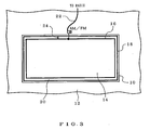
- An electrically conductive transparent film 14 may be used as shown in Fig.3 in the case that an antenna system is provided on a windshield.
- the structure of the antenna system is the same as in the side glass.
- the same element as in Fig.1 is designated by the same reference numeral.
- FM band 76-90MHz
- a maximum one wavelength is approximately 3.9m. It is understood that the antenna system may be provided on a windshield considering a shortening factor.
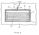
- a heating line or an electrically conductive transparent film may be used in the case that an antenna system is provided on a rear glass.
- Fig.4 shows an example in which a heating line 50 is used.
- a silver printed line 52 is formed surrounding the heating line 50 and is connected to the heating line 50.
- a loop-shaped silver printed line 18 is formed surrounding the silver printed line 52, which is capacitively coupled to the body. In this manner, an opening 20 is formed in a space between the printed lines 52 and 18.
- a short stub 24 is provided between the printed lines 52 and 18.
- a coaxial feeder 22 for AM/FM is connected to the antenna. It is preferable that a central conductor of the coaxing feeder 22 is connected to a feeding point 26 via a capacitor to prevent DC current through the heating line from flowing into the coaxial feeder 22.
- This glass antenna system functions in the same manner as the system in Fig.1.
Landscapes
- Physics & Mathematics (AREA)
- Electromagnetism (AREA)
- Details Of Aerials (AREA)
- Variable-Direction Aerials And Aerial Arrays (AREA)
- Waveguide Aerials (AREA)
Claims (9)
- Système d'antenne de vitre pour véhicules comprenant :une partie électriquement conductrice (14) formée sur une vitre (10) d'un véhicule sauf dans une région voisine d'une partie métallique (12) d'un véhicule entourant la vitre (10) ;une ligne imprimée électriquement conductrice en forme de boucle (18) formée dans la région de sorte qu'une ouverture (20) est formée entourant la partie électriquement conductrice (14) et de sorte d'être connectée de façon capacitive à la partie métallique (12) dans la bande FM, de sorte que l'ouverture (20) fonctionne comme une antenne à fentes et la ligne imprimée électriquement conductrice en forme de boucle (18) étant placée près de la partie électriquement conductrice (14) et près de la partie métallique (12) ; etune connexion électrique (24) entre la partie électriquement conductrice (14) et la ligne imprimée électriquement conductrice en forme de boucle (18) ;une ligne d'alimentation coaxiale (22), dont le conducteur central est connecté à la partie électriquement conductrice (14) et dont le conducteur externe est connecté à la partie métallique (12) ;
caractérisé en ce que la partie électriquement conductrice (14) et la ligne imprimée électriquement conductrice en forme de boucle (18) fonctionnent comme une antenne AM, et l'ouverture (20) fonctionne comme une antenne FM. - Système d'antenne pour véhicules selon la revendication 1, caractérisé en ce que la connexion électrique (24) est prévue au niveau d'une position où l'impédance de l'antenne à fentes formée par l'ouverture (20) est en adéquation avec celle de la ligne d'alimentation coaxiale (22).
- Système d'antenne pour véhicules selon la revendication 1, caractérisé en ce que la partie électriquement conductrice (14) est formée par un film transparent électriquement conducteur.
- Système d'antenne pour véhicules selon la revendication 3, caractérisé en ce qu'une ligne imprimée électriquement conductrice (16) est formée sur la partie périphérique du film transparent électriquement conducteur (14).
- Système d'antenne pour véhicules selon la revendication 1, caractérisé en ce que la partie électriquement conductrice (14) est constituée d'un motif électriquement conducteur en forme d'échelle (40, 42).
- Système d'antenne pour véhicules selon l'une quelconque des revendications 1 à 5, caractérisé en ce que la vitre (10) est une vitre latérale.
- Système d'antenne pour véhicules selon l'une quelconque des revendications 1 à 5, caractérisé en ce que la vitre (10) est un pare-brise.
- Système d'antenne pour véhicules selon la revendication 1, caractérisé en ce que la partie électriquement conductrice (14) est constituée d'une ligne chauffante (50) et d'une ligne imprimée électriquement conductrice (52) formée à la périphérie de la ligne chauffante (50).
- Système d'antenne pour véhicules selon la revendication 8, caractérisé en ce que la vitre (10) est une vitre arrière.
Applications Claiming Priority (2)
| Application Number | Priority Date | Filing Date | Title |
|---|---|---|---|
| JP2003175721A JP2005012588A (ja) | 2003-06-20 | 2003-06-20 | 車両用ガラスアンテナ装置 |
| JP2003175721 | 2003-06-20 |
Publications (2)
| Publication Number | Publication Date |
|---|---|
| EP1489680A1 EP1489680A1 (fr) | 2004-12-22 |
| EP1489680B1 true EP1489680B1 (fr) | 2006-11-15 |
Family
ID=33410998
Family Applications (1)
| Application Number | Title | Priority Date | Filing Date |
|---|---|---|---|
| EP04253668A Expired - Lifetime EP1489680B1 (fr) | 2003-06-20 | 2004-06-18 | Système d'antenne pour vitre de véhicule |
Country Status (5)
| Country | Link |
|---|---|
| US (1) | US6937198B2 (fr) |
| EP (1) | EP1489680B1 (fr) |
| JP (1) | JP2005012588A (fr) |
| AT (1) | ATE345584T1 (fr) |
| DE (1) | DE602004003171T2 (fr) |
Families Citing this family (16)
| Publication number | Priority date | Publication date | Assignee | Title |
|---|---|---|---|---|
| DE10146439C1 (de) * | 2001-09-20 | 2002-11-28 | Pilkington Automotive D Gmbh | Fahrzeugantennenscheibe |
| JP4021814B2 (ja) * | 2003-06-30 | 2007-12-12 | 本田技研工業株式会社 | 車載アンテナ |
| JP2005142616A (ja) * | 2003-11-04 | 2005-06-02 | Nippon Sheet Glass Co Ltd | 車両用ガラスアンテナおよび車両用ガラスアンテナ装置 |
| US7960854B2 (en) * | 2006-11-15 | 2011-06-14 | Pilkington Automotive Deutschland Gmbh | Electrical connector configured to form coupling region in automotive glazing |
| FR2936360B1 (fr) * | 2008-09-24 | 2011-04-01 | Saint Gobain | Procede de fabrication d'un masque a ouvertures submillimetriques pour grille electroconductrice submillimetrique, masque et grille electroconductrice submillimetrique. |
| US8872703B2 (en) | 2009-01-16 | 2014-10-28 | Saint-Gobain Glass France | Transparent, flat antenna, suitable for transmitting and receiving electromagnetic waves, method for the production thereof, and use thereof |
| EP2453521B1 (fr) | 2009-07-09 | 2017-02-08 | Asahi Glass Company, Limited | Glace pour véhicule et antenne |
| US8466842B2 (en) | 2010-10-22 | 2013-06-18 | Pittsburgh Glass Works, Llc | Window antenna |
| US8576130B2 (en) | 2010-10-22 | 2013-11-05 | Pittsburgh Glass Works, Llc | Wideband antenna |
| JP6169586B2 (ja) | 2011-10-28 | 2017-07-26 | コーニング インコーポレイテッド | 赤外線反射能を有するガラス物品および同物品を製造する方法 |
| US9337525B2 (en) | 2014-02-03 | 2016-05-10 | Pittsburgh Glass Works, Llc | Hidden window antenna |
| CN107531562B (zh) | 2015-04-30 | 2021-05-28 | 康宁股份有限公司 | 具有离散的金属银层的导电制品及其制造方法 |
| JP6743486B2 (ja) * | 2016-05-24 | 2020-08-19 | Agc株式会社 | 車両用窓ガラス |
| US10608330B2 (en) * | 2017-11-14 | 2020-03-31 | Gm Global Technology Operations, Llc | Method and apparatus to conceal near transparent conductors |
| US10923795B2 (en) * | 2018-04-12 | 2021-02-16 | Pittsburgh Glass Works, Llc | Hidden multi-band window antenna |
| JPWO2024228350A1 (fr) * | 2023-05-01 | 2024-11-07 |
Family Cites Families (5)
| Publication number | Priority date | Publication date | Assignee | Title |
|---|---|---|---|---|
| DE3808401A1 (de) * | 1988-03-12 | 1989-09-21 | Blaupunkt Werke Gmbh | Sichtscheibe fuer fahrzeuge |
| KR0145052B1 (ko) * | 1993-12-29 | 1998-08-01 | 와다 요시히로 | 차량용 안테나 및 그 설정방법 |
| US6147654A (en) * | 1999-07-27 | 2000-11-14 | General Motors Corporation | AM defogger grounding system for vehicle window antennas |
| GB0017415D0 (en) * | 2000-07-14 | 2000-08-30 | Bsh Ind Ltd | Antenna |
| DE10146439C1 (de) * | 2001-09-20 | 2002-11-28 | Pilkington Automotive D Gmbh | Fahrzeugantennenscheibe |
-
2003
- 2003-06-20 JP JP2003175721A patent/JP2005012588A/ja not_active Withdrawn
-
2004
- 2004-06-18 EP EP04253668A patent/EP1489680B1/fr not_active Expired - Lifetime
- 2004-06-18 AT AT04253668T patent/ATE345584T1/de not_active IP Right Cessation
- 2004-06-18 DE DE602004003171T patent/DE602004003171T2/de not_active Expired - Fee Related
- 2004-06-21 US US10/872,622 patent/US6937198B2/en not_active Expired - Fee Related
Also Published As
| Publication number | Publication date |
|---|---|
| US6937198B2 (en) | 2005-08-30 |
| EP1489680A1 (fr) | 2004-12-22 |
| US20040257286A1 (en) | 2004-12-23 |
| DE602004003171T2 (de) | 2007-09-27 |
| DE602004003171D1 (de) | 2006-12-28 |
| JP2005012588A (ja) | 2005-01-13 |
| ATE345584T1 (de) | 2006-12-15 |
Similar Documents
| Publication | Publication Date | Title |
|---|---|---|
| EP1489680B1 (fr) | Système d'antenne pour vitre de véhicule | |
| EP1432071A2 (fr) | Dispositif d'antenne compacte avec une large gamme de fréquences resonantes | |
| KR101756859B1 (ko) | 고절연 안테나 시스템 | |
| US5363114A (en) | Planar serpentine antennas | |
| US7420517B2 (en) | High frequency wave glass antenna for an automobile and rear window glass sheet for an automobile | |
| US8217845B2 (en) | High frequency glass antenna for automobiles | |
| EP0568284B1 (fr) | Antenne pour fenêtre de véhicule | |
| US7109921B2 (en) | High-bandwidth multi-band antenna | |
| CN101388494B (zh) | 多天线整合模组 | |
| CN101902001A (zh) | 连接器、配置有该连接器的天线及具有该天线的车辆用窗玻璃 | |
| US7106253B2 (en) | Compact antenna device | |
| EP0588514A1 (fr) | Antenne hybride monopole/logarithmique périodique | |
| EP0866515A2 (fr) | Système d'antenne de vitre | |
| US20070097001A1 (en) | Mobile antenna mounted on a vehicle body | |
| EP1530253A1 (fr) | Antenne sur vitre et système d'antenne incorporé dans une vitre pour véhicules | |
| RU2211509C2 (ru) | Излучатель, многочастотная антенна | |
| US4975713A (en) | Mobile mesh antenna | |
| CN102185176A (zh) | 天线 | |
| JPH03113901A (ja) | 2本線ループアンテナ | |
| JP2008022538A (ja) | 自動車用高周波ガラスアンテナ | |
| CN114389020A (zh) | 天线结构 | |
| JP2005012587A (ja) | 車両用ガラスアンテナ装置 | |
| US20040125033A1 (en) | Dual-band antenna having high horizontal sensitivity | |
| JPH03114303A (ja) | 広帯域ループアンテナ | |
| EP2190058A1 (fr) | Antenne pour vitre et vitre de fenêtre pour véhicule |
Legal Events
| Date | Code | Title | Description |
|---|---|---|---|
| PUAI | Public reference made under article 153(3) epc to a published international application that has entered the european phase |
Free format text: ORIGINAL CODE: 0009012 |
|
| AK | Designated contracting states |
Kind code of ref document: A1 Designated state(s): AT BE BG CH CY CZ DE DK EE ES FI FR GB GR HU IE IT LI LU MC NL PL PT RO SE SI SK TR |
|
| AX | Request for extension of the european patent |
Extension state: AL HR LT LV MK |
|
| 17P | Request for examination filed |
Effective date: 20050419 |
|
| 17Q | First examination report despatched |
Effective date: 20050622 |
|
| AKX | Designation fees paid |
Designated state(s): AT BE BG CH CY CZ DE DK EE ES FI FR GB GR HU IE IT LI LU MC NL PL PT RO SE SI SK TR |
|
| GRAP | Despatch of communication of intention to grant a patent |
Free format text: ORIGINAL CODE: EPIDOSNIGR1 |
|
| GRAS | Grant fee paid |
Free format text: ORIGINAL CODE: EPIDOSNIGR3 |
|
| GRAA | (expected) grant |
Free format text: ORIGINAL CODE: 0009210 |
|
| RAP1 | Party data changed (applicant data changed or rights of an application transferred) |
Owner name: NIPPON SHEET GLASS COMPANY, LIMITED |
|
| AK | Designated contracting states |
Kind code of ref document: B1 Designated state(s): AT BE BG CH CY CZ DE DK EE ES FI FR GB GR HU IE IT LI LU MC NL PL PT RO SE SI SK TR |
|
| PG25 | Lapsed in a contracting state [announced via postgrant information from national office to epo] |
Ref country code: SK Free format text: LAPSE BECAUSE OF FAILURE TO SUBMIT A TRANSLATION OF THE DESCRIPTION OR TO PAY THE FEE WITHIN THE PRESCRIBED TIME-LIMIT Effective date: 20061115 Ref country code: PL Free format text: LAPSE BECAUSE OF FAILURE TO SUBMIT A TRANSLATION OF THE DESCRIPTION OR TO PAY THE FEE WITHIN THE PRESCRIBED TIME-LIMIT Effective date: 20061115 Ref country code: FI Free format text: LAPSE BECAUSE OF FAILURE TO SUBMIT A TRANSLATION OF THE DESCRIPTION OR TO PAY THE FEE WITHIN THE PRESCRIBED TIME-LIMIT Effective date: 20061115 Ref country code: CH Free format text: LAPSE BECAUSE OF FAILURE TO SUBMIT A TRANSLATION OF THE DESCRIPTION OR TO PAY THE FEE WITHIN THE PRESCRIBED TIME-LIMIT Effective date: 20061115 Ref country code: IT Free format text: LAPSE BECAUSE OF FAILURE TO SUBMIT A TRANSLATION OF THE DESCRIPTION OR TO PAY THE FEE WITHIN THE PRESCRIBED TIME-LIMIT;WARNING: LAPSES OF ITALIAN PATENTS WITH EFFECTIVE DATE BEFORE 2007 MAY HAVE OCCURRED AT ANY TIME BEFORE 2007. THE CORRECT EFFECTIVE DATE MAY BE DIFFERENT FROM THE ONE RECORDED. Effective date: 20061115 Ref country code: NL Free format text: LAPSE BECAUSE OF FAILURE TO SUBMIT A TRANSLATION OF THE DESCRIPTION OR TO PAY THE FEE WITHIN THE PRESCRIBED TIME-LIMIT Effective date: 20061115 Ref country code: BE Free format text: LAPSE BECAUSE OF FAILURE TO SUBMIT A TRANSLATION OF THE DESCRIPTION OR TO PAY THE FEE WITHIN THE PRESCRIBED TIME-LIMIT Effective date: 20061115 Ref country code: CZ Free format text: LAPSE BECAUSE OF FAILURE TO SUBMIT A TRANSLATION OF THE DESCRIPTION OR TO PAY THE FEE WITHIN THE PRESCRIBED TIME-LIMIT Effective date: 20061115 Ref country code: RO Free format text: LAPSE BECAUSE OF FAILURE TO SUBMIT A TRANSLATION OF THE DESCRIPTION OR TO PAY THE FEE WITHIN THE PRESCRIBED TIME-LIMIT Effective date: 20061115 Ref country code: SI Free format text: LAPSE BECAUSE OF FAILURE TO SUBMIT A TRANSLATION OF THE DESCRIPTION OR TO PAY THE FEE WITHIN THE PRESCRIBED TIME-LIMIT Effective date: 20061115 Ref country code: LI Free format text: LAPSE BECAUSE OF FAILURE TO SUBMIT A TRANSLATION OF THE DESCRIPTION OR TO PAY THE FEE WITHIN THE PRESCRIBED TIME-LIMIT Effective date: 20061115 Ref country code: AT Free format text: LAPSE BECAUSE OF FAILURE TO SUBMIT A TRANSLATION OF THE DESCRIPTION OR TO PAY THE FEE WITHIN THE PRESCRIBED TIME-LIMIT Effective date: 20061115 |
|
| REG | Reference to a national code |
Ref country code: GB Ref legal event code: FG4D |
|
| REG | Reference to a national code |
Ref country code: CH Ref legal event code: EP |
|
| REF | Corresponds to: |
Ref document number: 602004003171 Country of ref document: DE Date of ref document: 20061228 Kind code of ref document: P |
|
| REG | Reference to a national code |
Ref country code: IE Ref legal event code: FG4D |
|
| PG25 | Lapsed in a contracting state [announced via postgrant information from national office to epo] |
Ref country code: DK Free format text: LAPSE BECAUSE OF FAILURE TO SUBMIT A TRANSLATION OF THE DESCRIPTION OR TO PAY THE FEE WITHIN THE PRESCRIBED TIME-LIMIT Effective date: 20070215 Ref country code: BG Free format text: LAPSE BECAUSE OF FAILURE TO SUBMIT A TRANSLATION OF THE DESCRIPTION OR TO PAY THE FEE WITHIN THE PRESCRIBED TIME-LIMIT Effective date: 20070215 Ref country code: SE Free format text: LAPSE BECAUSE OF FAILURE TO SUBMIT A TRANSLATION OF THE DESCRIPTION OR TO PAY THE FEE WITHIN THE PRESCRIBED TIME-LIMIT Effective date: 20070215 |
|
| PG25 | Lapsed in a contracting state [announced via postgrant information from national office to epo] |
Ref country code: ES Free format text: LAPSE BECAUSE OF FAILURE TO SUBMIT A TRANSLATION OF THE DESCRIPTION OR TO PAY THE FEE WITHIN THE PRESCRIBED TIME-LIMIT Effective date: 20070226 |
|
| PG25 | Lapsed in a contracting state [announced via postgrant information from national office to epo] |
Ref country code: PT Free format text: LAPSE BECAUSE OF FAILURE TO SUBMIT A TRANSLATION OF THE DESCRIPTION OR TO PAY THE FEE WITHIN THE PRESCRIBED TIME-LIMIT Effective date: 20070416 |
|
| NLV1 | Nl: lapsed or annulled due to failure to fulfill the requirements of art. 29p and 29m of the patents act | ||
| REG | Reference to a national code |
Ref country code: CH Ref legal event code: PL |
|
| ET | Fr: translation filed | ||
| PLBE | No opposition filed within time limit |
Free format text: ORIGINAL CODE: 0009261 |
|
| STAA | Information on the status of an ep patent application or granted ep patent |
Free format text: STATUS: NO OPPOSITION FILED WITHIN TIME LIMIT |
|
| 26N | No opposition filed |
Effective date: 20070817 |
|
| PG25 | Lapsed in a contracting state [announced via postgrant information from national office to epo] |
Ref country code: MC Free format text: LAPSE BECAUSE OF NON-PAYMENT OF DUE FEES Effective date: 20070630 |
|
| REG | Reference to a national code |
Ref country code: FR Ref legal event code: ST Effective date: 20080229 |
|
| PG25 | Lapsed in a contracting state [announced via postgrant information from national office to epo] |
Ref country code: DE Free format text: LAPSE BECAUSE OF NON-PAYMENT OF DUE FEES Effective date: 20080101 Ref country code: GR Free format text: LAPSE BECAUSE OF FAILURE TO SUBMIT A TRANSLATION OF THE DESCRIPTION OR TO PAY THE FEE WITHIN THE PRESCRIBED TIME-LIMIT Effective date: 20070216 |
|
| PG25 | Lapsed in a contracting state [announced via postgrant information from national office to epo] |
Ref country code: IE Free format text: LAPSE BECAUSE OF NON-PAYMENT OF DUE FEES Effective date: 20070618 |
|
| PG25 | Lapsed in a contracting state [announced via postgrant information from national office to epo] |
Ref country code: FR Free format text: LAPSE BECAUSE OF NON-PAYMENT OF DUE FEES Effective date: 20070702 |
|
| PG25 | Lapsed in a contracting state [announced via postgrant information from national office to epo] |
Ref country code: EE Free format text: LAPSE BECAUSE OF FAILURE TO SUBMIT A TRANSLATION OF THE DESCRIPTION OR TO PAY THE FEE WITHIN THE PRESCRIBED TIME-LIMIT Effective date: 20061115 |
|
| GBPC | Gb: european patent ceased through non-payment of renewal fee |
Effective date: 20080618 |
|
| PG25 | Lapsed in a contracting state [announced via postgrant information from national office to epo] |
Ref country code: GB Free format text: LAPSE BECAUSE OF NON-PAYMENT OF DUE FEES Effective date: 20080618 |
|
| PG25 | Lapsed in a contracting state [announced via postgrant information from national office to epo] |
Ref country code: CY Free format text: LAPSE BECAUSE OF FAILURE TO SUBMIT A TRANSLATION OF THE DESCRIPTION OR TO PAY THE FEE WITHIN THE PRESCRIBED TIME-LIMIT Effective date: 20061115 Ref country code: LU Free format text: LAPSE BECAUSE OF NON-PAYMENT OF DUE FEES Effective date: 20070618 |
|
| PG25 | Lapsed in a contracting state [announced via postgrant information from national office to epo] |
Ref country code: TR Free format text: LAPSE BECAUSE OF FAILURE TO SUBMIT A TRANSLATION OF THE DESCRIPTION OR TO PAY THE FEE WITHIN THE PRESCRIBED TIME-LIMIT Effective date: 20061115 Ref country code: HU Free format text: LAPSE BECAUSE OF FAILURE TO SUBMIT A TRANSLATION OF THE DESCRIPTION OR TO PAY THE FEE WITHIN THE PRESCRIBED TIME-LIMIT Effective date: 20070516 |