EP1489702A1 - Frequenzselektive verlustarme Übertragungsleitungseinrichtung - Google Patents
Frequenzselektive verlustarme Übertragungsleitungseinrichtung Download PDFInfo
- Publication number
- EP1489702A1 EP1489702A1 EP04013766A EP04013766A EP1489702A1 EP 1489702 A1 EP1489702 A1 EP 1489702A1 EP 04013766 A EP04013766 A EP 04013766A EP 04013766 A EP04013766 A EP 04013766A EP 1489702 A1 EP1489702 A1 EP 1489702A1
- Authority
- EP
- European Patent Office
- Prior art keywords
- impedance
- connector
- conductor
- transmission line
- coaxial
- Prior art date
- Legal status (The legal status is an assumption and is not a legal conclusion. Google has not performed a legal analysis and makes no representation as to the accuracy of the status listed.)
- Withdrawn
Links
- 230000005540 biological transmission Effects 0.000 title claims abstract description 68
- 239000004020 conductor Substances 0.000 claims abstract description 123
- 230000008878 coupling Effects 0.000 claims abstract description 28
- 238000010168 coupling process Methods 0.000 claims abstract description 28
- 238000005859 coupling reaction Methods 0.000 claims abstract description 28
- 230000007246 mechanism Effects 0.000 claims abstract description 7
- 239000011324 bead Substances 0.000 claims description 18
- 230000001131 transforming effect Effects 0.000 claims description 16
- 230000007704 transition Effects 0.000 claims description 10
- 230000013011 mating Effects 0.000 claims description 8
- 239000012212 insulator Substances 0.000 claims 12
- 230000003750 conditioning effect Effects 0.000 claims 1
- 238000009434 installation Methods 0.000 abstract description 5
- 210000004907 gland Anatomy 0.000 description 13
- 239000002184 metal Substances 0.000 description 13
- 229910052751 metal Inorganic materials 0.000 description 13
- -1 polyethylene Polymers 0.000 description 11
- 239000004698 Polyethylene Substances 0.000 description 10
- 229920000573 polyethylene Polymers 0.000 description 10
- 239000007787 solid Substances 0.000 description 8
- 238000013461 design Methods 0.000 description 5
- 239000000463 material Substances 0.000 description 5
- 239000004812 Fluorinated ethylene propylene Substances 0.000 description 4
- 238000004891 communication Methods 0.000 description 4
- HQQADJVZYDDRJT-UHFFFAOYSA-N ethene;prop-1-ene Chemical group C=C.CC=C HQQADJVZYDDRJT-UHFFFAOYSA-N 0.000 description 4
- 238000009413 insulation Methods 0.000 description 4
- 229920009441 perflouroethylene propylene Polymers 0.000 description 4
- 239000004809 Teflon Substances 0.000 description 3
- 229920006362 Teflon® Polymers 0.000 description 3
- 239000006260 foam Substances 0.000 description 3
- RYGMFSIKBFXOCR-UHFFFAOYSA-N Copper Chemical compound [Cu] RYGMFSIKBFXOCR-UHFFFAOYSA-N 0.000 description 2
- 229910052802 copper Inorganic materials 0.000 description 2
- 239000010949 copper Substances 0.000 description 2
- 230000000694 effects Effects 0.000 description 2
- 230000004888 barrier function Effects 0.000 description 1
- 238000010276 construction Methods 0.000 description 1
- 239000003989 dielectric material Substances 0.000 description 1
- 238000010348 incorporation Methods 0.000 description 1
- 239000004620 low density foam Substances 0.000 description 1
- 238000012986 modification Methods 0.000 description 1
- 230000004048 modification Effects 0.000 description 1
- 229920001343 polytetrafluoroethylene Polymers 0.000 description 1
- 239000004810 polytetrafluoroethylene Substances 0.000 description 1
- 230000001681 protective effect Effects 0.000 description 1
- 230000005855 radiation Effects 0.000 description 1
- 238000012360 testing method Methods 0.000 description 1
Images




Classifications
-
- H—ELECTRICITY
- H01—ELECTRIC ELEMENTS
- H01R—ELECTRICALLY-CONDUCTIVE CONNECTIONS; STRUCTURAL ASSOCIATIONS OF A PLURALITY OF MUTUALLY-INSULATED ELECTRICAL CONNECTING ELEMENTS; COUPLING DEVICES; CURRENT COLLECTORS
- H01R24/00—Two-part coupling devices, or either of their cooperating parts, characterised by their overall structure
- H01R24/38—Two-part coupling devices, or either of their cooperating parts, characterised by their overall structure having concentrically or coaxially arranged contacts
- H01R24/40—Two-part coupling devices, or either of their cooperating parts, characterised by their overall structure having concentrically or coaxially arranged contacts specially adapted for high frequency
- H01R24/42—Two-part coupling devices, or either of their cooperating parts, characterised by their overall structure having concentrically or coaxially arranged contacts specially adapted for high frequency comprising impedance matching means or electrical components, e.g. filters or switches
- H01R24/44—Two-part coupling devices, or either of their cooperating parts, characterised by their overall structure having concentrically or coaxially arranged contacts specially adapted for high frequency comprising impedance matching means or electrical components, e.g. filters or switches comprising impedance matching means
-
- H—ELECTRICITY
- H01—ELECTRIC ELEMENTS
- H01R—ELECTRICALLY-CONDUCTIVE CONNECTIONS; STRUCTURAL ASSOCIATIONS OF A PLURALITY OF MUTUALLY-INSULATED ELECTRICAL CONNECTING ELEMENTS; COUPLING DEVICES; CURRENT COLLECTORS
- H01R24/00—Two-part coupling devices, or either of their cooperating parts, characterised by their overall structure
- H01R24/38—Two-part coupling devices, or either of their cooperating parts, characterised by their overall structure having concentrically or coaxially arranged contacts
- H01R24/40—Two-part coupling devices, or either of their cooperating parts, characterised by their overall structure having concentrically or coaxially arranged contacts specially adapted for high frequency
- H01R24/56—Two-part coupling devices, or either of their cooperating parts, characterised by their overall structure having concentrically or coaxially arranged contacts specially adapted for high frequency specially adapted to a specific shape of cables, e.g. corrugated cables, twisted pair cables, cables with two screens or hollow cables
- H01R24/564—Corrugated cables
-
- H—ELECTRICITY
- H01—ELECTRIC ELEMENTS
- H01R—ELECTRICALLY-CONDUCTIVE CONNECTIONS; STRUCTURAL ASSOCIATIONS OF A PLURALITY OF MUTUALLY-INSULATED ELECTRICAL CONNECTING ELEMENTS; COUPLING DEVICES; CURRENT COLLECTORS
- H01R24/00—Two-part coupling devices, or either of their cooperating parts, characterised by their overall structure
- H01R24/38—Two-part coupling devices, or either of their cooperating parts, characterised by their overall structure having concentrically or coaxially arranged contacts
- H01R24/40—Two-part coupling devices, or either of their cooperating parts, characterised by their overall structure having concentrically or coaxially arranged contacts specially adapted for high frequency
- H01R24/56—Two-part coupling devices, or either of their cooperating parts, characterised by their overall structure having concentrically or coaxially arranged contacts specially adapted for high frequency specially adapted to a specific shape of cables, e.g. corrugated cables, twisted pair cables, cables with two screens or hollow cables
- H01R24/566—Hollow cables
-
- H—ELECTRICITY
- H01—ELECTRIC ELEMENTS
- H01R—ELECTRICALLY-CONDUCTIVE CONNECTIONS; STRUCTURAL ASSOCIATIONS OF A PLURALITY OF MUTUALLY-INSULATED ELECTRICAL CONNECTING ELEMENTS; COUPLING DEVICES; CURRENT COLLECTORS
- H01R2103/00—Two poles
Definitions
- This invention relates to a transmission line system that is optimized for low loss. More particularly, the invention relates to a transmission line system and a connector for communicating a coaxial cable of one impedance with a device of another impedance with low losses.
- a communication industry transmission standard is a 50 ohm impedance for communication systems.
- a 75 ohm coaxial transmission cable has lower attenuation characteristics and a higher operating frequency than a 50 ohm coaxial transmission cable, thus making the 75 ohm transmission cable a better choice for some broadcast applications and CATV industries.
- broadcast systems may require separate matching transformers to convert the impedance back to a typical 50 ohm device and CATV systems require 75 ohm mating connectors and amplifiers to integrate the 75 ohm cables into the respective systems.
- One specific application is the use of telecommunication cables in the PCS band for mobile telephones.
- the frequency band for this service is 1850 to 1990 MHz in the United States. This band involves very high frequencies, but not high enough to justify the cost of waveguides or tower loading to lower the attenuation. Therefore, a system is desired that reduces signal loss while having low product and implementation cost.
- the present invention is directed to a communication system comprising a signal on a coaxial transmission line which provides lower attenuation given the frequency of the signal, and a mating connector.
- the connector includes an integral connector transformer with optimized impedance for matching a low loss cable such as the 70 ohm coaxial transmission line to 50 ohm devices through an interface.
- the 70 ohm transmission cable typically includes low-density foam and a smooth hollow tube center conductor.
- a corrugated tube or solid wire could be used depending on the overall diameter of the cable.
- the outer conductor of the cable is typically made of an annular corrugated copper tube configured to simplify connector installation and provide flexibility. Other designs for the outer conductor are possible, designs such as smooth or helical corrugations.
- the connector includes means for attaching the connector to the cable as will be discussed further.
- the connector comprises an integral quarter wave transformer designed for the desired frequency of operation and standard means of attaching the connector to cable conductors by providing electrical contacts.
- the stub is reversed for a solid center conductor with a hollow center conductor of the connector.
- there is an integral transformer and a series quarter wave open circuit outer stub that capacitively couples to an outer conductor of a coaxial transmission cable.
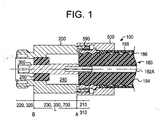
- FIG. 1 A cross sectional view of a frequency selective low loss coaxial electrical connector 100 is shown in FIG. 1.
- the connector 100 is used to connect a first coaxial transmission line 180 with a first impedance to an electrical device (not shown) with a second impedance.
- the first coaxial transmission line 180 has an impedance of 70 ohms and the electrical device is a second coaxial transmission line with the communication industry standard impedance of 50 ohms.
- the impedance of coaxial transmission line 180 is selected to provide the minimum attenuation depending on the construction and material used.
- first coaxial transmission line 180 and the electrical device can take on different impedance values than the ones above.
- First coaxial transmission line 180 includes a typically smooth hollow tube center conductor 182A surrounded by an insulation 184 with a dielectric constant ⁇ 1 .
- the insulation 184 is made of any suitable dielectric, including, for example, solid polyethylene, foamed polyethylene, Teflon (polytetrafluoroethylene), fluorinated ethylene propylene, and foamed fluorinated ethylene propylene, or any material in combination with air.
- the choice of material and final foamed density will determine the dielectic constant and, therefore, the impedance that provides the lowest attenuation for a given size cable.
- the dielectric provides support to maintain the inner conductor on the axis of the cable.
- Surrounding the insulation 184 is an outer conductor 186.
- the outer conductor 186 is typically made of an annular corrugated copper sheet to provide flexibility and ease in attaching standard connectors.
- Surrounding the outer conductor 186 is a protective cover 188.
- First coaxial transmission line 180 is coupled to the connector 100.
- the connector 100 comprises a substantially cylindrical body 200 having a spaced first end portion 210, second end portion 220, and an elongate center portion 230 including a transformer section 700. It is noted that the substantially cylindrical body 200 is electrically conductive.
- the elongate center portion 230 is disposed between the first end portion 210 and the second end portion 220, and has an axial bore 240 therethrough. Additionally, there is a dielectric bead 250 with a dielectric constant ⁇ 2 fixed inside the axial bore 240 at an end of the center portion 230.
- the dielectric bead 250 is made of any suitable dielectric, including, for example, solid polyethylene, foamed polyethylene, Teflon, fluorinated ethylene propylene, and foamed fluorinated ethylene propylene.
- the dielectric bead 250 is made of solid Teflon.
- the bead 250 may or may not be part of transformer section 700.
- the metal member 300 there is a metal member 300 within the dielectric bead 250 and extending coaxially within the axial bore 240.
- the metal member 300 which is an inner conductor of the connector 100, has first and second end portions 310 and 320 corresponding to the first and second end portions 210 and 220 of the cylindrical body 200, and a center portion 330 corresponding to the center portion 230 of the cylindrical body 200.
- the metal member 300 is fixed in place and electrically insulated from the cylindrical body 200 by the dielectric bead 250.
- the first end portions 210 and 310 interfit with the first coaxial transmission line 180.
- the first end portion 210 of the cylindrical body 200 mates with the outer conductor 186 in metal-to-metal electrical contact through a clamping ferrule 590, and spring-type contacts of the first end portion 310 of the metal member 300 mates with the center conductor 182A in metal-to-metal electrical contact.
- spring-type contacts of the first end portion 310 of the metal member 300 mates with the center conductor 182A in metal-to-metal electrical contact.
- coupling mechanism 500 to mate the coaxial transmission line 180 to the cylindrical body 200. It is noted that there are numerous standard means in the art to couple cables and connectors, and they will not be described.
- the second end portions 220 and 320 are shaped to interfit or mate with an electrical device.
- the second end portions 220 and 320 comprise a standard 7-16 DIN-type cable interface to interfit with the electrical device.
- the second end portions 220 and 320 comprise a standard N-type cable interface (not pictured).
- the center portions 230 and 330, and the dielectric bead 250 cooperatively provide for a transformer impedance for matching the first impedance of the first coaxial transmission line 180 and the second impedance of the electrical device.
- the connector 100 has a characteristic impedance calculated by EQN. 1 below.
- Z char Z i ⁇ Z o
- Z char is a characteristic impedance of the transformer section in the connector
- Z i is an impedance of a coaxial transmission line
- Z o is an impedance of an electrical device.
- the maximum power is transferred when the load impedance, i.e., impedance of the electrical device, is the complex conjugate of the source impedance, i.e., impedance of the coaxial transmission line.
- Z char is the transforming impedance of the connector 100
- Z i is the impedance of the first coaxial transmission line 180
- Z o is the impedance of the electrical device 900.
- the characteristic impedance of a electrically conducting coaxial body is given by EQN. 2. wherein D is an inside diameter of an outer conductor, d is an outside diameter of an inner conductor, and ⁇ is a dielectric constant of a dielectric between the inner and the outer conductors.
- the inside diameter of the center portion 330 is D and the outside diameter of the center portion 230 is d.
- the dielectric constant of air surrounding the center portion 230 is ⁇ .
- a D substantially equivalent to the diameter of the outer conductor 186 of the first coaxial transmission line 180 results in a center portion 330 of the metal member 300 having a d different than the outside diameter of the center conductor 182A to provide for a Z char satisfying EQN.
- center portions 230 and 330 may have different configurations as long as their respective dimensions satisfy EQNS. 1 and 2.
- center portions 230 and 330, and the dielectric bead 250 comprise a matching transformer section 700.
- the components of the matching transformer section 700, i.e., center portions 230 and 330, and the dielectric bead 250 are integral to the connector 100.
- a transforming length L including the center portions 230 and 330, and the dielectric bead 250 has a value depending on the frequency of the signal carried in the connector 100.
- the distance of the transforming length L is from a first impedance transition A between the first impedance and the matching impedance, to a second impedance transition B between the matching impedance and the second impedance.
- the first impedance transition A is at the abutting terminal end of the first coaxial transmission line 180 and the second impedance transition B is at a side of the dielectric bead 250 abutting the second end portions 220 and 320.
- a 1920 GHz signal requires a transforming length L of 1.014 inches with solid polyethylene filling the complete cavity of transformer length.
- a connector without the dielectric bead 250 included in the transformer length L of one quarter wavelength in air requires a length of 1.475 inches for a 1920 GHz signal.
- the presence of the dielectric bead 250 allows for a shorter transforming length L and therefore a shorter connector.
- the final length of bead or percentage of dielectric will be determined by mechanical integrity and cost.
- a quarter wave transformer can provide a VSWR of approximately 1.02:1 for a signal in the frequency band of 1850 to 1990 MHz.
- VSWR is the result of reflected waves, and a lower VSWR ratio translates into lower levels of undesirable signal reflections resulting from the connection of transmission lines or devices with mismatched impedance.
- the transforming length L can comprise an integral multiple of quarter wavelengths depending on the desired bandwidth.
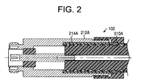
- FIG. 2 illustrates another embodiment of the invention.
- this embodiment differs in the following.
- a first end portion 210 of the cylindrical body 200 in electrical contact with the outer conductor 186 (FIG. 1)
- the capacitive coupling is created by the larger inside diameter of the first end portion 210 of the cylindrical body 200 of the connector 100 surrounding the cable 180.
- This cavity is preferably lined with a dielectric lining 214A to maintain the proper alignment of components between the series open circuit outer stub 212A and the outer conductor 186 and to prevent electrical contact.
- the dielectric lining 214A is made of a suitable dielectric material such as polyethylene.
- the embodiment includes a resilient gland 510A disposed at a distal end of the dielectric lining 214A.
- the coupling mechanism 500 has a hollow inner cavity and a step along the inner surface of the hollow inner cavity in which the resilient gland 510A is disposed.
- FIG. 3 Another embodiment of the invention is shown in FIG. 3. This embodiment differs with respect to the embodiment shown in FIG. 2 in the following. Capacitive coupling is created by an inner diameter of the outer conductor 186 of the coaxial cable 180 that is larger than the outside diameter of an open circuit outer stub 212B of a connector 103. Similar to the embodiment described in FIG. 2, the open circuit outer stub 212B is preferably covered with a dielectric 214B to maintain the proper alignment of the components. In this embodiment, the outer body of the cylindrical body 200 is substantially spaced apart from the cable outer conductor and the series open circuit outer stub 212B to create a quarter wave choke.
- the center conductor 182B of the coaxial transmission line 180 is solid and in electrical contact with a center portion 332A of a metal member 300.
- This stub design requires a special tool to cut the cavity in the foam 184. This type of tool is common in CATV cable connector installation.
- the series open circuit outer stub 212B is designed to cut the cavity into the foam 184 to eliminate the need for a special tool.
- a conductive member 520 disposed between the resilient gland 510B and a distal end of the outer body the connector 103.
- the conductive member 520 provides a more effective open circuit outer stub 212B by creating an electrical contact between the outer conductor 186 of the cable 180, the outer surface of the cylindrical body 200, i.e., the outer body of the connector.
- the resilient gland 510B in this case is conductive to provide electrical contact to the cable 180.
- FIG. 4 illustrates another embodiment of the invention.
- This embodiment of the connector 104 differs from the embodiment shown in FIG. 1 in the following regard.
- a series open circuit inner stub 312A capacitively coupled to the center conductor 182A.
- the outer diameter of the series open circuit inner stub 312A is less than the inside diameter of the hollow cavity in the center conductor 182A.
- a dielectric sleeve 314A of suitable material such as polyethylene to maintain the series open circuit inner stub 312A in proper alignment with respect to the center conductor 182A and to prevent electrical contact.
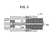
- FIG. 5 an another embodiment is shown in FIG. 5. This embodiment is different from the embodiment shown in FIG. 1 with respect to the following.
- a connector 105 there is a series open circuit inner stub 332B at the center portion 330 of the metal member 300.
- the series open circuit inner stub 332B has a hollow cavity in which a projecting solid end portion of an inner conductor 182B of the coaxial transmission line 180 is disposed.
- the inside diameter of the hollow cavity is greater than the outer diameter of the solid inner conductor 182B.
- a dielectric lining 324 is preferably disposed on the inside surface of the hollow cavity to maintain proper alignment of the components and to prevent electrical contact. This design is applicable to smaller cables that are made with solid center conductors.
- FIG. 6 illustrates yet another embodiment of the invention. With respect to the embodiment shown in FIG. 2, this embodiment differs in the following respect.
- This embodiment combines the inner capacitive coupling configuration shown in FIG. 4 with the outer capacitive coupling configuration shown in FIG. 2.
- the impedance property of each of the two stubs 212C, 312C will normally need to be modified when the two stubs are combined to maintain the correct impedance to conjugate the reactance of the transformer section 700 over the desired bandwidth.
- FIG. 7 Radially around the series open circuit outer stub 212D, there is an outer choke 600, i.e., a short circuit stub.
- the choke 600 is a dielectric layer such as an air gap, preferably, or a dielectric sleeve, that is disposed within first end portion 210 of the cylindrical body 100 of the connector 107. With an air gap, the choke 600 is physically longer than quarter wavelength dielectric loaded stub.
- the embodiment includes the conductive member 520 and conductive gland 510B.
- the conductivity of the gland 510B need not be high since the gland 510B is disposed at a high-impedance position where low current exists.
- the resilient gland 510B may replace the conductive member 520 depending on the conductivity of the resilient gland 510B.
- the length of the series open stub inner conductors and the series open stub outer conductors is electrically one quarter wave long.
- the quarter wave in polyethylene is 1.014 inches long for a 1920 MHz signal.
- the inner stub can provide less than 10 ohm impedance and the outer stub will be approximately 25 ohms impedance with a corrugated outer conductor.
- the exact physical length of the stub is usually determined by test since the volume of cavity created by conductors and connector is a combination of dielectric and air to maintain the slip fit requirement for field installation of connector.
- the cable of the present invention has low losses given the state of the art of the materials for cables such as foam polyethylene with densities below 0.18 g/cm utilized to effect the invention.
- the use of at least one series open circuit stub conductor as in FIG. 2-7 provides improved bandwidth characteristic over a connector using only a simple quarter wavelength transformer (FIG. 1).
- the series open stubs and the integral transformer as shown in FIG. 6 of the present invention allows for a greater bandwidth covering the worldwide PCS band of 1700 to 2300 MHz with a VSWR of less than 1.02:1.
- a connector without the series open stubs, i.e., embodiment shown in FIG. 1, covers a frequency band of 1850 to 1990 MHz with a VSWR of about 1.02:1.
- the incorporation of the series open stub conductor allows for simplified connector installation by allowing for less precise cutting of the coaxial transmission cable and less critical torque requirements to install the connector.
- the utilization of a non-metallic connector contact through the use of a dielectric sleeve allows the connector to be hand tightened._
- capacitively coupling both inner and outer conductors eliminates all passive intermodulation (PIM) from the most likely source while eliminating the most expensive and complicated parts of the connector.
- the connector In use, the connector only needs to be hand tightened to properly connect the coaxial transmission line to the connector because the use of open circuit stubs reduce the need for precise electrical metal to metal contact between the coaxial transmission line and the connector.
Landscapes
- Coupling Device And Connection With Printed Circuit (AREA)
- Details Of Connecting Devices For Male And Female Coupling (AREA)
Applications Claiming Priority (2)
| Application Number | Priority Date | Filing Date | Title |
|---|---|---|---|
| US10/464,731 US6882242B2 (en) | 2003-06-19 | 2003-06-19 | Frequency selective low loss transmission line system |
| US464731 | 2003-06-19 |
Publications (1)
| Publication Number | Publication Date |
|---|---|
| EP1489702A1 true EP1489702A1 (de) | 2004-12-22 |
Family
ID=33418161
Family Applications (1)
| Application Number | Title | Priority Date | Filing Date |
|---|---|---|---|
| EP04013766A Withdrawn EP1489702A1 (de) | 2003-06-19 | 2004-06-11 | Frequenzselektive verlustarme Übertragungsleitungseinrichtung |
Country Status (3)
| Country | Link |
|---|---|
| US (1) | US6882242B2 (de) |
| EP (1) | EP1489702A1 (de) |
| CN (1) | CN100492782C (de) |
Cited By (6)
| Publication number | Priority date | Publication date | Assignee | Title |
|---|---|---|---|---|
| EP1523073A2 (de) | 2003-10-09 | 2005-04-13 | Radio Frequency Systems, Inc. | Abgestimmter Koaxialverbinder im Radiofrequenzbereich |
| WO2008131741A1 (de) * | 2007-04-25 | 2008-11-06 | Spinner Gmbh | Hochfrequenzbauteil mit geringen dielektrischen verlusten |
| CN102334232A (zh) * | 2009-02-25 | 2012-01-25 | 阿尔卡特朗讯 | 用于传输高频信号的同轴电缆的机械和电连接设备 |
| CN102066905B (zh) * | 2008-04-14 | 2015-11-25 | 通用电气公司 | 基于空芯波导的拉曼系统和方法 |
| DE102007063622B4 (de) * | 2007-06-04 | 2021-06-02 | Rose Systemtechnik Gmbh | Bedienstation mit einem Rechnergehäuse, einem Tragarm und einer zwischen dem Rechnergehäuse und dem Tragarm angeordneten mechanischen Kupplung mit selbsttätiger elektrischer Kopplung |
| EP3832811A1 (de) * | 2019-12-02 | 2021-06-09 | Corning Optical Communications ApS | Anordnungen von koaxialkabeln mit klemm- und greifelementen |
Families Citing this family (28)
| Publication number | Priority date | Publication date | Assignee | Title |
|---|---|---|---|---|
| US7240292B2 (en) | 2003-04-17 | 2007-07-03 | Microsoft Corporation | Virtual address bar user interface control |
| US7823077B2 (en) | 2003-03-24 | 2010-10-26 | Microsoft Corporation | System and method for user modification of metadata in a shell browser |
| US7712034B2 (en) | 2003-03-24 | 2010-05-04 | Microsoft Corporation | System and method for shell browser |
| US7769794B2 (en) | 2003-03-24 | 2010-08-03 | Microsoft Corporation | User interface for a file system shell |
| US7421438B2 (en) | 2004-04-29 | 2008-09-02 | Microsoft Corporation | Metadata editing control |
| US7627552B2 (en) | 2003-03-27 | 2009-12-01 | Microsoft Corporation | System and method for filtering and organizing items based on common elements |
| US7925682B2 (en) | 2003-03-27 | 2011-04-12 | Microsoft Corporation | System and method utilizing virtual folders |
| US7650575B2 (en) | 2003-03-27 | 2010-01-19 | Microsoft Corporation | Rich drag drop user interface |
| US8024335B2 (en) | 2004-05-03 | 2011-09-20 | Microsoft Corporation | System and method for dynamically generating a selectable search extension |
| US7657846B2 (en) | 2004-04-23 | 2010-02-02 | Microsoft Corporation | System and method for displaying stack icons |
| US7694236B2 (en) | 2004-04-23 | 2010-04-06 | Microsoft Corporation | Stack icons representing multiple objects |
| US8707209B2 (en) | 2004-04-29 | 2014-04-22 | Microsoft Corporation | Save preview representation of files being created |
| US7614016B2 (en) | 2005-04-21 | 2009-11-03 | Microsoft Corporation | Multiple roots in navigation pane |
| US8195646B2 (en) | 2005-04-22 | 2012-06-05 | Microsoft Corporation | Systems, methods, and user interfaces for storing, searching, navigating, and retrieving electronic information |
| US7665028B2 (en) | 2005-07-13 | 2010-02-16 | Microsoft Corporation | Rich drag drop user interface |
| US7374455B2 (en) * | 2006-10-19 | 2008-05-20 | John Mezzalingua Associates, Inc. | Connector assembly for a cable having a radially facing conductive surface and method of operatively assembling the connector assembly |
| JP2009147556A (ja) * | 2007-12-12 | 2009-07-02 | Sony Corp | アンテナ、通信装置及びアンテナ製造方法 |
| CN101662432B (zh) * | 2008-08-30 | 2013-03-20 | 华为技术有限公司 | 一种传输方法、系统及装置 |
| CN102576947A (zh) * | 2009-06-05 | 2012-07-11 | 安德鲁有限责任公司 | 夹持和夹紧同轴连接器 |
| CN103199398A (zh) * | 2012-01-10 | 2013-07-10 | 镇江华坚电子有限公司 | 一种n型阻抗转换器 |
| RU2485650C1 (ru) * | 2012-01-30 | 2013-06-20 | Российская Федерация, от имени которой выступает Государственная корпорация по атомной энергии "Росатом" | Высокотемпературный коаксиальный кабельный разъем |
| US8801460B2 (en) * | 2012-11-09 | 2014-08-12 | Andrew Llc | RF shielded capacitively coupled connector |
| US9270071B2 (en) * | 2013-03-13 | 2016-02-23 | International Business Machines Corporation | Microwave connector with filtering properties |
| US9300029B2 (en) | 2013-03-15 | 2016-03-29 | International Business Machines Corporation | Coaxial transmission line slot filter with absorptive matrix |
| EP2962368B1 (de) * | 2013-06-17 | 2019-05-15 | CommScope Technologies LLC | Koaxialkabel und verbinder mit kapazitiver kopplung |
| CN105958227A (zh) * | 2016-06-17 | 2016-09-21 | 北京无线电计量测试研究所 | 一种射频同轴连接器 |
| EP4275251A4 (de) * | 2021-01-08 | 2024-11-13 | Corning Optical Communications RF LLC | Koaxialverbinderanordnung mit verriegelungshülse |
| US11936134B2 (en) | 2021-01-08 | 2024-03-19 | Corning Optical Communications Rf Llc | Coaxial connector assembly having locking ferrule |
Citations (2)
| Publication number | Priority date | Publication date | Assignee | Title |
|---|---|---|---|---|
| US2490622A (en) | 1941-01-15 | 1949-12-06 | Emi Ltd | High-frequency transmission line or cable and connector therefor |
| US3492604A (en) * | 1964-09-09 | 1970-01-27 | Amp Inc | Impedance matching means and method |
Family Cites Families (11)
| Publication number | Priority date | Publication date | Assignee | Title |
|---|---|---|---|---|
| US3681718A (en) | 1969-11-12 | 1972-08-01 | Baytron Co Inc | Millimeter wave translating device with changeable insert element |
| US4153885A (en) | 1977-05-23 | 1979-05-08 | Helmut Bacher | Microwave equalizer with coaxial cable resonant stubs |
| US4358174A (en) | 1980-03-31 | 1982-11-09 | Sealectro Corporation | Interconnected assembly of an array of high frequency coaxial connectors |
| US4675633A (en) | 1985-08-05 | 1987-06-23 | Harris Corporation | Waveguide expansion joint |
| US5198786A (en) | 1991-12-04 | 1993-03-30 | Raytheon Company | Waveguide transition circuit |
| US5327111A (en) | 1992-09-16 | 1994-07-05 | Westinghouse Electric Corp. | Motion insensitive phase compensated coaxial connector |
| US5463405A (en) | 1994-05-20 | 1995-10-31 | Valor Enterprises, Inc. | Cellular telephone coupling network |
| EP0820649B1 (de) * | 1995-04-12 | 1999-10-13 | Itt Industries Limited | Elektrischer verbinder |
| US5532657A (en) | 1995-05-23 | 1996-07-02 | International Business Machines Corporation | High speed coaxial contact and signal transmission element |
| AUPP482498A0 (en) * | 1998-07-23 | 1998-08-13 | A.C. & E. Pty Limited | Balun and associated method for connecting cables |
| US6452105B2 (en) | 2000-01-12 | 2002-09-17 | Meggitt Safety Systems, Inc. | Coaxial cable assembly with a discontinuous outer jacket |
-
2003
- 2003-06-19 US US10/464,731 patent/US6882242B2/en not_active Expired - Lifetime
-
2004
- 2004-05-19 CN CNB2004100383378A patent/CN100492782C/zh not_active Expired - Lifetime
- 2004-06-11 EP EP04013766A patent/EP1489702A1/de not_active Withdrawn
Patent Citations (2)
| Publication number | Priority date | Publication date | Assignee | Title |
|---|---|---|---|---|
| US2490622A (en) | 1941-01-15 | 1949-12-06 | Emi Ltd | High-frequency transmission line or cable and connector therefor |
| US3492604A (en) * | 1964-09-09 | 1970-01-27 | Amp Inc | Impedance matching means and method |
Cited By (8)
| Publication number | Priority date | Publication date | Assignee | Title |
|---|---|---|---|---|
| EP1523073A2 (de) | 2003-10-09 | 2005-04-13 | Radio Frequency Systems, Inc. | Abgestimmter Koaxialverbinder im Radiofrequenzbereich |
| EP1523073A3 (de) * | 2003-10-09 | 2008-04-23 | Radio Frequency Systems, Inc. | Abgestimmter Koaxialverbinder im Radiofrequenzbereich |
| WO2008131741A1 (de) * | 2007-04-25 | 2008-11-06 | Spinner Gmbh | Hochfrequenzbauteil mit geringen dielektrischen verlusten |
| DE102007063622B4 (de) * | 2007-06-04 | 2021-06-02 | Rose Systemtechnik Gmbh | Bedienstation mit einem Rechnergehäuse, einem Tragarm und einer zwischen dem Rechnergehäuse und dem Tragarm angeordneten mechanischen Kupplung mit selbsttätiger elektrischer Kopplung |
| CN102066905B (zh) * | 2008-04-14 | 2015-11-25 | 通用电气公司 | 基于空芯波导的拉曼系统和方法 |
| CN102334232A (zh) * | 2009-02-25 | 2012-01-25 | 阿尔卡特朗讯 | 用于传输高频信号的同轴电缆的机械和电连接设备 |
| CN102334232B (zh) * | 2009-02-25 | 2014-08-13 | 阿尔卡特朗讯 | 用于传输高频信号的同轴电缆的机械和电连接设备 |
| EP3832811A1 (de) * | 2019-12-02 | 2021-06-09 | Corning Optical Communications ApS | Anordnungen von koaxialkabeln mit klemm- und greifelementen |
Also Published As
| Publication number | Publication date |
|---|---|
| CN100492782C (zh) | 2009-05-27 |
| CN1574499A (zh) | 2005-02-02 |
| US6882242B2 (en) | 2005-04-19 |
| US20040257169A1 (en) | 2004-12-23 |
Similar Documents
| Publication | Publication Date | Title |
|---|---|---|
| US6882242B2 (en) | Frequency selective low loss transmission line system | |
| US6926555B2 (en) | Tuned radio frequency coaxial connector | |
| US7381089B2 (en) | Coaxial cable-connector termination | |
| CN102362392B (zh) | 多频带天线组件 | |
| US7934952B2 (en) | Coaxial cable connector system and method | |
| US9276302B2 (en) | Waveguide rotary joint including half-height waveguide portions | |
| CN101036264B (zh) | 天线馈电结构 | |
| US20130100571A1 (en) | Fully isolated coaxial surge protector | |
| RU2260229C1 (ru) | Многоканальное вращающееся сочленение (варианты) | |
| US6828944B2 (en) | Multi-band sleeve dipole antenna | |
| US5619213A (en) | Antenna coupler for a portable radio | |
| US20210367385A1 (en) | Cable arrangement | |
| US6215449B1 (en) | Systems and methods for coaxially coupling an antenna through an insulator | |
| US5579023A (en) | Rotatable antenna and integral, shielded impedance matching network | |
| KR102140867B1 (ko) | Rf케이블 일체형 전력분배기 | |
| US10193335B2 (en) | Radio frequency surge protector with matched piston-cylinder cavity shape | |
| US20050077981A1 (en) | Radio frequency connector port with isolation function | |
| US5309125A (en) | Compact delay line formed of concentrically stacked, helically grooved, cylindrical channel-line structure | |
| EP2033309B1 (de) | Übertragungsleitungssymmetrieschaltung für breitbandkombinatoren, -splitter und -transformatoren | |
| KR101651014B1 (ko) | 광대역 동축 커넥터 | |
| US20240136781A1 (en) | Systems and methods for coaxial board to board connections | |
| KR20090000040U (ko) | 고전력용 sma 커넥터 | |
| KR20080020890A (ko) | 동축 커넥터 구조체 | |
| HK1025677B (en) | Coaxial broadband surge voltage arrester | |
| HK1025677A1 (en) | Coaxial broadband surge voltage arrester |
Legal Events
| Date | Code | Title | Description |
|---|---|---|---|
| PUAI | Public reference made under article 153(3) epc to a published international application that has entered the european phase |
Free format text: ORIGINAL CODE: 0009012 |
|
| AK | Designated contracting states |
Kind code of ref document: A1 Designated state(s): AT BE BG CH CY CZ DE DK EE ES FI FR GB GR HU IE IT LI LU MC NL PL PT RO SE SI SK TR |
|
| AX | Request for extension of the european patent |
Extension state: AL HR LT LV MK |
|
| 17P | Request for examination filed |
Effective date: 20050621 |
|
| AKX | Designation fees paid |
Designated state(s): AT BE BG CH CY CZ DE DK EE ES FI FR GB GR HU IE IT LI LU MC NL PL PT RO SE SI SK TR |
|
| RAP1 | Party data changed (applicant data changed or rights of an application transferred) |
Owner name: ALCATEL LUCENT |
|
| 17Q | First examination report despatched |
Effective date: 20090406 |
|
| RAP1 | Party data changed (applicant data changed or rights of an application transferred) |
Owner name: ALCATEL LUCENT |
|
| 111Z | Information provided on other rights and legal means of execution |
Free format text: AT BE BG CH CY CZ DE DK EE ES FI FR GB GR HU IE IT LI LU MC NL PL PT RO SE SI SK TR Effective date: 20130410 |
|
| RAP1 | Party data changed (applicant data changed or rights of an application transferred) |
Owner name: ALCATEL LUCENT |
|
| D11X | Information provided on other rights and legal means of execution (deleted) | ||
| GRAP | Despatch of communication of intention to grant a patent |
Free format text: ORIGINAL CODE: EPIDOSNIGR1 |
|
| INTG | Intention to grant announced |
Effective date: 20150508 |
|
| STAA | Information on the status of an ep patent application or granted ep patent |
Free format text: STATUS: THE APPLICATION IS DEEMED TO BE WITHDRAWN |
|
| 18D | Application deemed to be withdrawn |
Effective date: 20150919 |