EP1489712A2 - Zugentlastung für ein Elektrokabel - Google Patents
Zugentlastung für ein Elektrokabel Download PDFInfo
- Publication number
- EP1489712A2 EP1489712A2 EP04013973A EP04013973A EP1489712A2 EP 1489712 A2 EP1489712 A2 EP 1489712A2 EP 04013973 A EP04013973 A EP 04013973A EP 04013973 A EP04013973 A EP 04013973A EP 1489712 A2 EP1489712 A2 EP 1489712A2
- Authority
- EP
- European Patent Office
- Prior art keywords
- clamping
- base part
- strain relief
- cable
- guide
- Prior art date
- Legal status (The legal status is an assumption and is not a legal conclusion. Google has not performed a legal analysis and makes no representation as to the accuracy of the status listed.)
- Granted
Links
Images

Classifications
-
- H—ELECTRICITY
- H02—GENERATION; CONVERSION OR DISTRIBUTION OF ELECTRIC POWER
- H02G—INSTALLATION OF ELECTRIC CABLES OR LINES, OR OF COMBINED OPTICAL AND ELECTRIC CABLES OR LINES
- H02G3/00—Installations of electric cables or lines or protective tubing therefor in or on buildings, equivalent structures or vehicles
- H02G3/02—Details
- H02G3/08—Distribution boxes; Connection or junction boxes
- H02G3/081—Bases, casings or covers
Definitions
- the invention relates to a strain relief for an electric cable according to the preamble of Claim 1.
- strain reliefs for electric cables known in which one with a channel-shaped cable receptacle for the electric cable provided base part which is fixed to a housing of an electrical appliance, with a the base part bridging clamping part is connected, wherein the clamping part on the base part is locked by means of a locking or clip device while the electric cable between the base part and clamping part is clamped.
- Such a strain relief is known from DE 200 04 983 U1, in which the clamping part two spaced legs each having a guide portion and one with the Guide section bending elastic connected latching section with a toothing having.
- the teeth provided with the legs of the clamping part are used for Clamp the cable in formed on two webs of the base guides inserted.
- At the two webs of the base part is also in each case a toothing attached, wherein the teeth on the two webs of the base part inwards show and with the clamping part on the outwardly facing teeth as Interengage locking device.
- Each of the two legs of the clamping part has also at the free ends of an extension, wherein by a to the end extended force by squeezing the thighs Detent device is releasable.
- a strain relief for a direct connection of supply and / or Control lines to an electric motor arranged in a housing is known from DE 199 50 189 A1 known.
- the strain relief which formed in a housing on the Plug-in shaft is inserted, consists of two integral, a film hinge interconnected receiving parts for the lines, by folding be clamped over the film hinge between the receiving parts.
- the lock the two receiving parts is generated by means of a locking device.
- a strain relief for an electrical cable which is formed on a connector housing is known from DE 29 03 954 C2.
- a clamping part with two V-shaped Provided thighs, which can be inserted in a likewise V-shaped locking part and can be latched and in the locked state, the legs of the clamping part of the electric cable pinch.
- a known from DE 100 45 714 A1 connector for a flat film conductor has a strain relief for the flat film conductor, in which the flat film conductor between a carrier part and a belt hinge with the carrier part connected clamping part is clamped.
- a tab on the clamping part molded, which formed in the closed clamping position in a carrier part Engaging opening engages.
- the clamping part on two pins which by two in the Flat film conductors grasp existing bushings and in two on the carrier part engage formed openings.
- Object of the present invention is to provide a strain relief for an electric cable create that is compact and easy to install, and beyond can be produced inexpensively.
- the object is with a strain relief according to the characterizing features of Claim 1 solved.
- the strain relief according to the invention has the two Thighs of the base part with respect to the cable receptacle one outwards pointing gearing, which with an inwardly pointing gearing of the Clamping part cooperates. This allows the strain relief in width, d. H. limit to a small amount perpendicular to the direction of the cable run.
- the Strain relief according to the invention is thus characterized by a compact design and is also easy to install.
- the electric cable To clamp the electric cable must only the clamping part inserted into the guide webs of the base part and by a essentially vertical pressure on the clamping part in the direction of the in the recording posted electrical cable are pressed, with the clamping part through the Locking device locked to the base part. The electric cable is thereby in the electrical Connection point kept mechanically unloaded in the device.
- each assigned a guide bar on the legs of each toothing is, on which a trained on the clamping part guide receptacle is guided, and that the Guide webs each one-sided and parallel next to the teeth are arranged outside the recording, lie the gears and the guides in Cable running direction one behind the other. This is no additional for the guides Space in the width of the strain relief necessary and the compactness can continue increase.
- a particularly advantageous embodiment in terms of compactness is that the guides on the base part as L-shaped guide webs and the Guide shots on the clamping part as grooves in U-shaped end sections Side walls are formed.
- the strain relief shown in the figures is in one piece, for example as Injection molded part made of plastic and is attached to a housing 10 of a Electrical appliance, such as an electric stove used.
- the in the housing 10th used strain relief is shown in Figure 3 and 4.
- This has a housing wall 11 of the housing 10 an opening 12, in which the strain relief, as later is inserted by clipping is used.
- One of the strain relief fixed Electric cable 13 is through the opening 12 into the interior of the housing 10 to a not shown connection point.
- the cable running direction of the electric cable 13 with respect to the plane of the housing wall 11 extends in accordance with the line I - I in Figure 2. With respect to a rectangular plane to the housing wall 11 which runs Electric cable 13 according to Figure 4 at an angle inclined in the direction of the connection point in the housing 10.
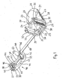
- the strain relief is shown in Figure 1 and 2 of a base member 20 and a bridge-like clamping member 40 together, wherein the clamping member 40 by means of a flexible Band hinge 60 is coupled to the base part 20.
- the base part 20 has a device-side circumferential support frame 21 with a bottom opening 22.
- On the Support frame 21 sit vertically two base side side walls 23, between which a cable insertion opening 24 is formed.
- the Cable guide 37 is covered by a raised cover 25.
- the cover 25 extends from the Jardineintechnologymaschine réelle 24, for example, inclined by 30 degrees Support frame 21 out.
- the cover 25 goes on the support frame 21 in example a arcuate support edge 26 via, which forms a housing-side support surface 27, with in the installed state, the base part 20 rests on the housing wall 11 (Figure 4).
- On the support frame 21 are each parallel to the side walls 23 two resilient Clip strips 28 arranged after the Einclipsen of the base member 20 in the opening 12th
- the housing wall 11 engage behind from the inside.
- To lock the Base part 20 in the opening 12 is on the support frame 21 further comprises a stop web 29th formed, the housing wall 11 during insertion of the base member 20 from the inside engages behind ( Figure 4).
- the strain relief covers the whole Opening 12, so that there is an effective cut edge protection at the opening 12.
- Frontally in front of the cable entry opening 24 are two laterally substantially parallel to the side walls 23 extending legs 30, each in height above the Jardineinrawö réelle 24 protrude.
- the two legs 30 form between them a cable receptacle 31 from the base a base part-side clamping edge 32 with a arcuate cutting edge 34 has.
- the cable receptacle 31 is opposite to Clamping edge 32 open at the top. Outside the cable receptacle 31 is connected to the Legs 30 each have a base part-side teeth 33 executed in the Substantially extends over the entire height of the legs 30. Also outside of Cable receptacle 31 extends next to the two teeth 33 each have an L-shaped Guide web 35.
- the two L-shaped guide webs 35 are viewed from the front behind the respective toothing 33 and immediately after the respective teeth 33 of the legs 30 formed.
- the clamping member 40 has a front wall 41, from the right-angled two parallel extending clamping member side walls 42 each having a U-shaped end portion 44 lead away.
- the U-shaped end portions 44 each form a groove 46 as Guide receptacle for the guide webs 35 of the base part 20 from.
- On the front wall 41 is a first clamping member side clamping edge 43 with an arcuate front Cutting edge 45 is formed.
- a second clamping part side Clamping edge 47 is arranged.
- a rear arcuate cutting edge 48 is formed at the second clamp-side clamping edge 47.
- a clamping web 50 Spaced apart from the side walls 42 is in each case a clamping web 50, each having one clamping-side toothing 51 formed on the clamping part 40.
- the two clamping bars 50 are on one side with the front wall 41 and laterally over one Support web 52 connected to the respective side wall 44 ( Figure 2).
- the connection of the Clamp 50 with the front wall 41 and the side wall 44 is designed so that the Clamping webs 50 substantially at right angles to the direction of cable bending elastic are.
- the toothing 51 is attached to the inside of the clamping web 50, that is, that the teeth 51 on the two opposite clamping webs 50th to each other.
- At the clamping bars 50 are each further extensions 53rd molded, the frontal over the front wall 41 protrude.
- a gap 54 is formed in each case of the respective right angles a guide gap 55 to the groove 46 branches off.
- the gap 54 which is the is provided upstream of the clamping member side toothing 51, serves to receive the legs 30 of the Base part 20 in the clamping part 40.
- An additional guide of the clamping part 40 on the base part 20 in the direction of the cable path is engaged by the engaging in the guide webs 35 Grooves 46 realized, as described in more detail below in connection with Figure 5 becomes.
- FIG. 1 An illustration of the strain relief in the clamping position is shown in FIG. It is the base member 20 inserted into the opening 12 of the housing.
- the electric cable 13 is through the bottom opening 22 and through the cable insertion opening 24 of the base part 20th guided according to Figure 4 and clamped by means of the clamping part 40 on the base part 20.
- To is the connected to the hinge 60 with the base member 20 clamping member 40 for Base member 20 pivoted out and with the two columns 54 on the two legs 30th pushed.
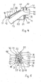
- the two grooves 46 engage with the two L-shaped Guide webs 35 of the base part 2, wherein, as shown in the enlarged section according to Figure 5 shows, the L-shaped guide web 35 through the guide gap 55 in the respective groove 46 engages.
- To simplify the Einsteckvorganges are on the thighs 30 in the region of the toothing 33 each insertion bevels 36 attached. Additional Insertion bevels 56 are respectively located on the clamping webs 50 (FIG. 1).
- the distance between the opposing clamping webs 50 is dimensioned such that the clamping-side teeth 51 in the base part-side toothing 33 to the Legs 30 engage under bias of the flexurally elastic clamping webs 50.
- the teeth of the gears 33 and 51 are each undercut executed so that they engage behind the form-locking engagement and thus a Lock opening movement of the clamping member 40.
- the clamping position of the clamping member 40 is achieved by the plugged on clamping part 40 a substantially vertically acting pressure force is applied and thereby the Clamping part 40 slides on the guide webs 35 in the direction of the electric cable 13 and while the two cutting edges 45, 48 of the clamping edges 43, 47 on the electric cable thirteenth to press.
- the inserted electric cable 13 is located in the cable receptacle 31st on the there attached cutting edge 34 of the base part-side clamping edge 32. Is a applied sufficient pressure force, so that a clamping of the electric cable 13th can be realized, the compressive force is taken from the clamping member 40 and the teeth 33, 51 engage, so that the clamping part 40 is blocked on the base part 20.
- the cutting edges of the clamping edges are expediently designed so that they act against the pulling direction of the electric cable 13 and have and tensile stress of the electric cable 13 in the insulation press (Figure 4).
- the position of the clamping edges 32, 45, 47 is also designed so that the base part-side clamping edge 32 with the Cutting edge 34 between the two clamping edges 43, 47 of the clamping member 40 with respect to Electric cable 13 is located, expediently the rear edge 48 of the clamping edge 47 is slightly lower than the front edge 45 of the clamping edge 43 ( Figure 4).
- a solution of the latching is possible by the extension 53 a Force is applied, which presses the bending elastic clamping webs 50 apart, so that the teeth of the teeth 51 from the teeth of the teeth 33rd be pulled out and thereby releases the locking.
- a fast Clamping and a quick solution of the clamping of the electric cable 13 in the Strain relief possible without tools.
Landscapes
- Engineering & Computer Science (AREA)
- Architecture (AREA)
- Civil Engineering (AREA)
- Structural Engineering (AREA)
- Installation Of Indoor Wiring (AREA)
- Details Of Connecting Devices For Male And Female Coupling (AREA)
- Clamps And Clips (AREA)
Abstract
Description
- Figur 1 eine perspektivische Darstellung der erfindungsgemäßen Zugentlastung,
- Figur 2 eine Draufsicht auf die Zugentlastung gemäß Figur 1,
- Figur 3 eine Frontalansicht der Zugentlastung gemäß Figur 1 in Klemmstellung,
- Figur 4 eine Schnittdarstellung nach der Line IV - IV in Figur 3 und
- Figur 5 einen vergrößerten Ausschnitt einer Teilschnittdarstellung nach der Linie V - IV in Figur 3.
Claims (10)
- Zugentlastung für ein Elektrokabel, mit einem an einem Gehäuse fixierten Basisteil (20) mit einer Kabelaufnahme (31) für das Elektrokabel (13) und einem die Kabelaufnahme am Basisteil brückenartig überspannenden Klemmteil (40), wobei das Klemmteil mit dem Basisteil mittels einer Rastvorrichtung zum Festklemmen des Elektrokabels verbindbar ist und wobei die Rastvorrichtung durch Verzahnungen am Basisteil und am Klemmteil ausgebildet ist, dadurch gekennzeichnet, dass die Verzahnungen (33) des Basisteils (20) jeweils an gegenüberliegenden Schenkeln (30) nach außen weisend und die Verzahnungen (51) des Klemmteils (40) jeweils an gegenüberliegenden Klemmstegen (50) nach innen weisend angeordnet sind.
- Zugentlastung nach Anspruch 1, dadurch gekennzeichnet, dass an den Schenkeln (30) des Basisteils (20) der Verzahnung (33) jeweils ein Führungssteg (35) zugeordnet ist, an dem jeweils eine am Klemmteil (40) ausgebildete Führungsaufnahme (44, 46) geführt ist.
- Zugentlastung nach Anspruch 2, dadurch gekennzeichnet, dass die Führungsstege (35) an den Schenkeln (30) des Basisteils (20) jeweils neben den Verzahnungen (33) außerhalb der Kabelaufnahme (31) angeordnet sind.
- Zugentlastung nach Anspruch 2 oder 3, dadurch gekennzeichnet, dass die Führungsstege (35) an den Schenkel (30) des Basisteils (20) jeweils L-förmig ausgeführt sind und die Führungsaufnahmen an dem Klemmteil (40) jeweils eine Nut (46) aufweisen, die in den jeweiligen L-förmigen Führungssteg (35) eingreift.
- Zugentlastung nach Anspruch 4, dadurch gekennzeichnet, dass die Nut (46) von einem an je einer Seitenwand (42) des Klemmteils (40) ausgebildeten U-förmigen Endabschnitt (44) gebildet ist.
- Zugentlastung nach einem der Ansprüche 1 bis 5, dadurch gekennzeichnet, dass sich an die Kabelaufnahme (31) eine Kabeleinführöffnung (24) anschließt, von der eine geneigt wegführende Kabelführung (37) zu einer Bodenöffnung (22) des Basisteils (20) führt.
- Zugentlastung nach Anspruch 6, dadurch gekennzeichnet, dass die Kabelführung (37) von einer erhabenen Abdeckung (25) überspannt ist.
- Zugentlastung nach einem der Ansprüche 1 bis 7, dadurch gekennzeichnet, dass in der Kabelaufnahme (31) des Basisteils (20) mindestens eine basisteilseitige Klemmkante (32) und an dem Klemmteil (40) mindestens zwei klemmteilseitige Klemmkanten (43, 47) ausgebildet sind, wobei in Klemmstellung des Elektrokabels (13) die basisteilseitige Klemmkante (32) zwischen den beiden klemmteilseitigen Klemmkanten (43, 47) liegt.
- Zugentlastung nach Anspruch 8, dadurch gekennzeichnet, dass zumindest eine der Klemmkanten (32, 43, 47) eine entgegen der Zugrichtung des Elektrokabels (13) wirkende Schneide (34, 45, 48) aufweist.
- Zugentlastung nach Anspruch 9, dadurch gekennzeichnet, dass die Schneiden (34, 45, 48) bogenförmig ausgeführt sind.
Priority Applications (1)
| Application Number | Priority Date | Filing Date | Title |
|---|---|---|---|
| PL04013973T PL1489712T3 (pl) | 2003-06-16 | 2004-06-15 | Element odciążający dla kabla elektrycznego |
Applications Claiming Priority (2)
| Application Number | Priority Date | Filing Date | Title |
|---|---|---|---|
| DE10327043 | 2003-06-16 | ||
| DE10327043A DE10327043A1 (de) | 2003-06-16 | 2003-06-16 | Zugentlastung für ein Elektrokabel |
Publications (3)
| Publication Number | Publication Date |
|---|---|
| EP1489712A2 true EP1489712A2 (de) | 2004-12-22 |
| EP1489712A3 EP1489712A3 (de) | 2010-06-16 |
| EP1489712B1 EP1489712B1 (de) | 2015-11-11 |
Family
ID=33394837
Family Applications (1)
| Application Number | Title | Priority Date | Filing Date |
|---|---|---|---|
| EP04013973.5A Expired - Lifetime EP1489712B1 (de) | 2003-06-16 | 2004-06-15 | Zugentlastung für ein Elektrokabel |
Country Status (3)
| Country | Link |
|---|---|
| EP (1) | EP1489712B1 (de) |
| DE (1) | DE10327043A1 (de) |
| PL (1) | PL1489712T3 (de) |
Cited By (7)
| Publication number | Priority date | Publication date | Assignee | Title |
|---|---|---|---|---|
| EP2436987A2 (de) | 2010-09-29 | 2012-04-04 | BSH Bosch und Siemens Hausgeräte GmbH | Gargerät mit einer Anordnung zum Verhindern des Durchschneidens von Kabeln |
| EP2492563A1 (de) * | 2011-02-25 | 2012-08-29 | Raywal Holding SAS | Klemme für Leitung oder Kabel |
| DE202014103395U1 (de) | 2014-07-23 | 2015-10-26 | Wago Verwaltungsgesellschaft Mbh | Schelle |
| WO2017102248A1 (en) | 2015-12-18 | 2017-06-22 | BSH Hausgeräte GmbH | A household appliance having a cable protector element |
| WO2022061627A1 (en) | 2020-09-24 | 2022-03-31 | Tridonic Gmbh & Co Kg | Strain relief clamp |
| DE202023100899U1 (de) * | 2023-02-24 | 2024-05-27 | WAGO Verwaltungsgesellschaft mit beschränkter Haftung | Gehäusebauteile, Klemmelement, Set mit einem Gehäusebauteil und einem Klemmelement sowie Steckverbinder |
| US12620795B2 (en) | 2020-09-24 | 2026-05-05 | Tridonic Gmbh & Co Kg | Strain relief clamp |
Family Cites Families (15)
| Publication number | Priority date | Publication date | Assignee | Title |
|---|---|---|---|---|
| DE1940584U (de) * | 1966-04-21 | 1966-06-16 | Arburg Maschinenfabrik Hel & S | Kabelschelle. |
| DE2903954C2 (de) * | 1979-02-02 | 1987-02-19 | Kreutzenbeck, Hans, 5620 Velbert | Steckverbindergehäuse |
| DE3405126C2 (de) * | 1984-02-14 | 1985-12-05 | Philips Patentverwaltung Gmbh, 2000 Hamburg | Zugentlastungsaufsatz für Mehrfach-, insbesondere Flachbandkabel |
| IT1227022B (it) * | 1988-07-29 | 1991-03-08 | Ilme Spa | Connettore per cavi elettrici a spina e presa volante. |
| DE4317725A1 (de) * | 1992-06-01 | 1993-12-02 | Trw Fahrzeugelektrik | Elektrisches Anschlußelement |
| DE9303368U1 (de) * | 1993-03-08 | 1993-05-27 | Electro-Terminal Gesellschaft m.b.H., Innsbruck | Zugentlastungsvorrichtung |
| DE9409981U1 (de) * | 1994-06-21 | 1994-08-11 | Hwang, Chin-Hwa, San-Chung | Kabelgriffvorrichtung |
| DE4441230A1 (de) * | 1994-11-19 | 1996-05-23 | Sel Alcatel Ag | Gehäuse mit Vorrichtung zur Halterung von Anschlußkabeln |
| DE29608857U1 (de) * | 1996-05-17 | 1996-09-05 | EPV-electronik GmbH, 58809 Neuenrade | Anschlußgehäuse mit Abdeckhaube für ein elektrisches Gerät |
| US6126122A (en) * | 1997-11-06 | 2000-10-03 | Sioux Chief Manufacturing Co., Inc. | Double ratchet arm pipe clamp |
| DE10045714A1 (de) * | 1999-09-15 | 2001-05-17 | Whitaker Corp | Steckverbinder für zumindest einen Flachfolienleiter |
| DE19950189B4 (de) * | 1999-10-19 | 2004-04-15 | Bühler Motor GmbH | Stellantrieb, insbesondere zum Antrieb eines Kfz-Rückblickspiegels |
| DE20004983U1 (de) * | 2000-03-17 | 2001-07-26 | Tridonic Bauelemente Ges.M.B.H., Dornbirn | Zugentlastungsvorrichtung für ein elektrisches Kabel |
| DE20009788U1 (de) * | 2000-05-31 | 2000-09-07 | STOCKO Contact GmbH & Co. KG, 42327 Wuppertal | Steckverbinder zum Anschließen elektrischer Leitungen an eine Leipterplatte |
| FR2880211B1 (fr) * | 2004-12-23 | 2007-03-09 | Valeo Electronique Sys Liaison | Dispositif de fixation de gaines annelees |
-
2003
- 2003-06-16 DE DE10327043A patent/DE10327043A1/de not_active Withdrawn
-
2004
- 2004-06-15 PL PL04013973T patent/PL1489712T3/pl unknown
- 2004-06-15 EP EP04013973.5A patent/EP1489712B1/de not_active Expired - Lifetime
Cited By (9)
| Publication number | Priority date | Publication date | Assignee | Title |
|---|---|---|---|---|
| EP2436987A2 (de) | 2010-09-29 | 2012-04-04 | BSH Bosch und Siemens Hausgeräte GmbH | Gargerät mit einer Anordnung zum Verhindern des Durchschneidens von Kabeln |
| EP2492563A1 (de) * | 2011-02-25 | 2012-08-29 | Raywal Holding SAS | Klemme für Leitung oder Kabel |
| DE202014103395U1 (de) | 2014-07-23 | 2015-10-26 | Wago Verwaltungsgesellschaft Mbh | Schelle |
| WO2017102248A1 (en) | 2015-12-18 | 2017-06-22 | BSH Hausgeräte GmbH | A household appliance having a cable protector element |
| WO2022061627A1 (en) | 2020-09-24 | 2022-03-31 | Tridonic Gmbh & Co Kg | Strain relief clamp |
| EP4000135A4 (de) * | 2020-09-24 | 2023-05-24 | Tridonic GmbH & Co KG | Zugentlastungsklammer |
| CN116888831A (zh) * | 2020-09-24 | 2023-10-13 | 赤多尼科两合股份有限公司 | 应变消除夹具 |
| US12620795B2 (en) | 2020-09-24 | 2026-05-05 | Tridonic Gmbh & Co Kg | Strain relief clamp |
| DE202023100899U1 (de) * | 2023-02-24 | 2024-05-27 | WAGO Verwaltungsgesellschaft mit beschränkter Haftung | Gehäusebauteile, Klemmelement, Set mit einem Gehäusebauteil und einem Klemmelement sowie Steckverbinder |
Also Published As
| Publication number | Publication date |
|---|---|
| EP1489712B1 (de) | 2015-11-11 |
| EP1489712A3 (de) | 2010-06-16 |
| PL1489712T3 (pl) | 2016-05-31 |
| DE10327043A1 (de) | 2005-01-05 |
Similar Documents
| Publication | Publication Date | Title |
|---|---|---|
| EP2377203B1 (de) | Klemmfeder für eine federkraftklemme | |
| DE102014102517B4 (de) | Verbindungsklemme und Federkraftklemmkontakt hierzu | |
| DE102011055919B4 (de) | Anschlussklemme | |
| DE102020110979A1 (de) | Steckverbinder einer elektrischen Steckverbindung sowie damit gebildete elektrische Steckverbindung | |
| EP3734771B1 (de) | Set aus einer elektrischen steckverbindung und einem funktionselement | |
| DE102013111551B3 (de) | Tragschienengehäuse | |
| DE102007040496A1 (de) | Kabelverbindungseinrichtung und Verbindungsvorrichtung mit derartigen Kabelverarbeitungseinrichtungen | |
| DE19714459A1 (de) | Steckverbinder mit einer Gehäuseverriegelung | |
| EP2606538B1 (de) | Steckverbinder | |
| WO2008095453A1 (de) | Elektrisches gerät und geräteanordnung | |
| DE102010010259A1 (de) | Steckverbinder und Gegensteckverbinder | |
| DE202010016894U1 (de) | Anschlussvorrichtung mit beweglichem Betätigungsmittel | |
| DE20003081U1 (de) | Kabelhaltevorrichtung | |
| EP1489712A2 (de) | Zugentlastung für ein Elektrokabel | |
| DE102016012370B4 (de) | Gehäuse zum Anschließen wenigstens einer Kabellitze eines Kabels | |
| DE102012218028A1 (de) | Stecker und Bausatz für einen Stecker | |
| WO2015127926A1 (de) | Steckverbinder | |
| EP1514330A1 (de) | Kontaktelement für eine elektrische steckverbindung | |
| DE102011054282B4 (de) | Anschlussklemme | |
| EP1359650B1 (de) | Anschlussvorrichtung für elektrische Verteiler | |
| EP0151690B1 (de) | Verbindungsanordnung mit Klemmelementen zur Verklemmung eines Flachkabels | |
| DE202013104941U1 (de) | Elektrische Steckverbinderanordnung und Schirmanbindungselement hierzu | |
| DE2558739C2 (de) | Rastende Steckverbindung | |
| DE69927870T2 (de) | Andruckkontaktanschlussklemme | |
| DE102024110585A1 (de) | Verriegelungselement, Steckverbinder und damit gebildete elektrische Steckverbindung |
Legal Events
| Date | Code | Title | Description |
|---|---|---|---|
| PUAI | Public reference made under article 153(3) epc to a published international application that has entered the european phase |
Free format text: ORIGINAL CODE: 0009012 |
|
| AK | Designated contracting states |
Kind code of ref document: A2 Designated state(s): AT BE BG CH CY CZ DE DK EE ES FI FR GB GR HU IE IT LI LU MC NL PL PT RO SE SI SK TR |
|
| AX | Request for extension of the european patent |
Extension state: AL HR LT LV MK |
|
| PUAL | Search report despatched |
Free format text: ORIGINAL CODE: 0009013 |
|
| AK | Designated contracting states |
Kind code of ref document: A3 Designated state(s): AT BE BG CH CY CZ DE DK EE ES FI FR GB GR HU IE IT LI LU MC NL PL PT RO SE SI SK TR |
|
| AX | Request for extension of the european patent |
Extension state: AL HR LT LV MK |
|
| 17P | Request for examination filed |
Effective date: 20101216 |
|
| AKX | Designation fees paid |
Designated state(s): AT BE BG CH CY CZ DE DK EE ES FI FR GB GR HU IE IT LI LU MC NL PL PT RO SE SI SK TR |
|
| 17Q | First examination report despatched |
Effective date: 20141217 |
|
| RAP1 | Party data changed (applicant data changed or rights of an application transferred) |
Owner name: BSH HAUSGERAETE GMBH |
|
| GRAP | Despatch of communication of intention to grant a patent |
Free format text: ORIGINAL CODE: EPIDOSNIGR1 |
|
| INTG | Intention to grant announced |
Effective date: 20150619 |
|
| GRAS | Grant fee paid |
Free format text: ORIGINAL CODE: EPIDOSNIGR3 |
|
| GRAA | (expected) grant |
Free format text: ORIGINAL CODE: 0009210 |
|
| AK | Designated contracting states |
Kind code of ref document: B1 Designated state(s): AT BE BG CH CY CZ DE DK EE ES FI FR GB GR HU IE IT LI LU MC NL PL PT RO SE SI SK TR |
|
| REG | Reference to a national code |
Ref country code: GB Ref legal event code: FG4D Free format text: NOT ENGLISH |
|
| REG | Reference to a national code |
Ref country code: CH Ref legal event code: EP |
|
| REG | Reference to a national code |
Ref country code: IE Ref legal event code: FG4D Free format text: LANGUAGE OF EP DOCUMENT: GERMAN |
|
| REG | Reference to a national code |
Ref country code: AT Ref legal event code: REF Ref document number: 760876 Country of ref document: AT Kind code of ref document: T Effective date: 20151215 |
|
| REG | Reference to a national code |
Ref country code: DE Ref legal event code: R096 Ref document number: 502004015066 Country of ref document: DE |
|
| REG | Reference to a national code |
Ref country code: NL Ref legal event code: MP Effective date: 20160211 |
|
| PG25 | Lapsed in a contracting state [announced via postgrant information from national office to epo] |
Ref country code: ES Free format text: LAPSE BECAUSE OF FAILURE TO SUBMIT A TRANSLATION OF THE DESCRIPTION OR TO PAY THE FEE WITHIN THE PRESCRIBED TIME-LIMIT Effective date: 20151111 Ref country code: NL Free format text: LAPSE BECAUSE OF FAILURE TO SUBMIT A TRANSLATION OF THE DESCRIPTION OR TO PAY THE FEE WITHIN THE PRESCRIBED TIME-LIMIT Effective date: 20151111 |
|
| PG25 | Lapsed in a contracting state [announced via postgrant information from national office to epo] |
Ref country code: PT Free format text: LAPSE BECAUSE OF FAILURE TO SUBMIT A TRANSLATION OF THE DESCRIPTION OR TO PAY THE FEE WITHIN THE PRESCRIBED TIME-LIMIT Effective date: 20160311 Ref country code: SE Free format text: LAPSE BECAUSE OF FAILURE TO SUBMIT A TRANSLATION OF THE DESCRIPTION OR TO PAY THE FEE WITHIN THE PRESCRIBED TIME-LIMIT Effective date: 20151111 Ref country code: FI Free format text: LAPSE BECAUSE OF FAILURE TO SUBMIT A TRANSLATION OF THE DESCRIPTION OR TO PAY THE FEE WITHIN THE PRESCRIBED TIME-LIMIT Effective date: 20151111 Ref country code: GR Free format text: LAPSE BECAUSE OF FAILURE TO SUBMIT A TRANSLATION OF THE DESCRIPTION OR TO PAY THE FEE WITHIN THE PRESCRIBED TIME-LIMIT Effective date: 20160212 |
|
| REG | Reference to a national code |
Ref country code: FR Ref legal event code: PLFP Year of fee payment: 13 |
|
| PG25 | Lapsed in a contracting state [announced via postgrant information from national office to epo] |
Ref country code: CZ Free format text: LAPSE BECAUSE OF FAILURE TO SUBMIT A TRANSLATION OF THE DESCRIPTION OR TO PAY THE FEE WITHIN THE PRESCRIBED TIME-LIMIT Effective date: 20151111 |
|
| REG | Reference to a national code |
Ref country code: DE Ref legal event code: R097 Ref document number: 502004015066 Country of ref document: DE |
|
| PG25 | Lapsed in a contracting state [announced via postgrant information from national office to epo] |
Ref country code: SK Free format text: LAPSE BECAUSE OF FAILURE TO SUBMIT A TRANSLATION OF THE DESCRIPTION OR TO PAY THE FEE WITHIN THE PRESCRIBED TIME-LIMIT Effective date: 20151111 Ref country code: EE Free format text: LAPSE BECAUSE OF FAILURE TO SUBMIT A TRANSLATION OF THE DESCRIPTION OR TO PAY THE FEE WITHIN THE PRESCRIBED TIME-LIMIT Effective date: 20151111 Ref country code: DK Free format text: LAPSE BECAUSE OF FAILURE TO SUBMIT A TRANSLATION OF THE DESCRIPTION OR TO PAY THE FEE WITHIN THE PRESCRIBED TIME-LIMIT Effective date: 20151111 Ref country code: RO Free format text: LAPSE BECAUSE OF FAILURE TO SUBMIT A TRANSLATION OF THE DESCRIPTION OR TO PAY THE FEE WITHIN THE PRESCRIBED TIME-LIMIT Effective date: 20151111 |
|
| PLBE | No opposition filed within time limit |
Free format text: ORIGINAL CODE: 0009261 |
|
| STAA | Information on the status of an ep patent application or granted ep patent |
Free format text: STATUS: NO OPPOSITION FILED WITHIN TIME LIMIT |
|
| 26N | No opposition filed |
Effective date: 20160812 |
|
| PG25 | Lapsed in a contracting state [announced via postgrant information from national office to epo] |
Ref country code: SI Free format text: LAPSE BECAUSE OF FAILURE TO SUBMIT A TRANSLATION OF THE DESCRIPTION OR TO PAY THE FEE WITHIN THE PRESCRIBED TIME-LIMIT Effective date: 20151111 |
|
| PG25 | Lapsed in a contracting state [announced via postgrant information from national office to epo] |
Ref country code: BE Free format text: LAPSE BECAUSE OF NON-PAYMENT OF DUE FEES Effective date: 20160630 |
|
| PG25 | Lapsed in a contracting state [announced via postgrant information from national office to epo] |
Ref country code: MC Free format text: LAPSE BECAUSE OF FAILURE TO SUBMIT A TRANSLATION OF THE DESCRIPTION OR TO PAY THE FEE WITHIN THE PRESCRIBED TIME-LIMIT Effective date: 20151111 |
|
| REG | Reference to a national code |
Ref country code: CH Ref legal event code: PL |
|
| REG | Reference to a national code |
Ref country code: IE Ref legal event code: MM4A |
|
| PG25 | Lapsed in a contracting state [announced via postgrant information from national office to epo] |
Ref country code: CH Free format text: LAPSE BECAUSE OF NON-PAYMENT OF DUE FEES Effective date: 20160630 Ref country code: LI Free format text: LAPSE BECAUSE OF NON-PAYMENT OF DUE FEES Effective date: 20160630 |
|
| PG25 | Lapsed in a contracting state [announced via postgrant information from national office to epo] |
Ref country code: IE Free format text: LAPSE BECAUSE OF NON-PAYMENT OF DUE FEES Effective date: 20160615 |
|
| REG | Reference to a national code |
Ref country code: FR Ref legal event code: PLFP Year of fee payment: 14 |
|
| REG | Reference to a national code |
Ref country code: AT Ref legal event code: MM01 Ref document number: 760876 Country of ref document: AT Kind code of ref document: T Effective date: 20160615 |
|
| PG25 | Lapsed in a contracting state [announced via postgrant information from national office to epo] |
Ref country code: AT Free format text: LAPSE BECAUSE OF NON-PAYMENT OF DUE FEES Effective date: 20160615 |
|
| PG25 | Lapsed in a contracting state [announced via postgrant information from national office to epo] |
Ref country code: HU Free format text: LAPSE BECAUSE OF FAILURE TO SUBMIT A TRANSLATION OF THE DESCRIPTION OR TO PAY THE FEE WITHIN THE PRESCRIBED TIME-LIMIT; INVALID AB INITIO Effective date: 20040615 Ref country code: CY Free format text: LAPSE BECAUSE OF FAILURE TO SUBMIT A TRANSLATION OF THE DESCRIPTION OR TO PAY THE FEE WITHIN THE PRESCRIBED TIME-LIMIT Effective date: 20151111 |
|
| REG | Reference to a national code |
Ref country code: FR Ref legal event code: PLFP Year of fee payment: 15 |
|
| PG25 | Lapsed in a contracting state [announced via postgrant information from national office to epo] |
Ref country code: LU Free format text: LAPSE BECAUSE OF NON-PAYMENT OF DUE FEES Effective date: 20160615 |
|
| PG25 | Lapsed in a contracting state [announced via postgrant information from national office to epo] |
Ref country code: BG Free format text: LAPSE BECAUSE OF FAILURE TO SUBMIT A TRANSLATION OF THE DESCRIPTION OR TO PAY THE FEE WITHIN THE PRESCRIBED TIME-LIMIT Effective date: 20151111 |
|
| REG | Reference to a national code |
Ref country code: DE Ref legal event code: R084 Ref document number: 502004015066 Country of ref document: DE |
|
| PGFP | Annual fee paid to national office [announced via postgrant information from national office to epo] |
Ref country code: DE Payment date: 20190630 Year of fee payment: 16 |
|
| PGFP | Annual fee paid to national office [announced via postgrant information from national office to epo] |
Ref country code: TR Payment date: 20200615 Year of fee payment: 17 Ref country code: FR Payment date: 20200623 Year of fee payment: 17 |
|
| PGFP | Annual fee paid to national office [announced via postgrant information from national office to epo] |
Ref country code: PL Payment date: 20200603 Year of fee payment: 17 Ref country code: GB Payment date: 20200625 Year of fee payment: 17 |
|
| PGFP | Annual fee paid to national office [announced via postgrant information from national office to epo] |
Ref country code: IT Payment date: 20200630 Year of fee payment: 17 |
|
| REG | Reference to a national code |
Ref country code: DE Ref legal event code: R119 Ref document number: 502004015066 Country of ref document: DE |
|
| PG25 | Lapsed in a contracting state [announced via postgrant information from national office to epo] |
Ref country code: DE Free format text: LAPSE BECAUSE OF NON-PAYMENT OF DUE FEES Effective date: 20210101 |
|
| GBPC | Gb: european patent ceased through non-payment of renewal fee |
Effective date: 20210615 |
|
| PG25 | Lapsed in a contracting state [announced via postgrant information from national office to epo] |
Ref country code: GB Free format text: LAPSE BECAUSE OF NON-PAYMENT OF DUE FEES Effective date: 20210615 |
|
| PG25 | Lapsed in a contracting state [announced via postgrant information from national office to epo] |
Ref country code: FR Free format text: LAPSE BECAUSE OF NON-PAYMENT OF DUE FEES Effective date: 20210630 |
|
| PG25 | Lapsed in a contracting state [announced via postgrant information from national office to epo] |
Ref country code: IT Free format text: LAPSE BECAUSE OF NON-PAYMENT OF DUE FEES Effective date: 20210615 |
|
| PG25 | Lapsed in a contracting state [announced via postgrant information from national office to epo] |
Ref country code: PL Free format text: LAPSE BECAUSE OF NON-PAYMENT OF DUE FEES Effective date: 20210615 |