EP1489714B1 - Ermittlung elektromechanischer Schwingungen in Stromversorgungssystemen - Google Patents
Ermittlung elektromechanischer Schwingungen in Stromversorgungssystemen Download PDFInfo
- Publication number
- EP1489714B1 EP1489714B1 EP03405450A EP03405450A EP1489714B1 EP 1489714 B1 EP1489714 B1 EP 1489714B1 EP 03405450 A EP03405450 A EP 03405450A EP 03405450 A EP03405450 A EP 03405450A EP 1489714 B1 EP1489714 B1 EP 1489714B1
- Authority
- EP
- European Patent Office
- Prior art keywords
- model
- time
- power system
- parameters
- oscillations
- Prior art date
- Legal status (The legal status is an assumption and is not a legal conclusion. Google has not performed a legal analysis and makes no representation as to the accuracy of the status listed.)
- Expired - Lifetime
Links
Images

Classifications
-
- H—ELECTRICITY
- H02—GENERATION; CONVERSION OR DISTRIBUTION OF ELECTRIC POWER
- H02J—ELECTRIC POWER NETWORKS; CIRCUIT ARRANGEMENTS OR SYSTEMS FOR SUPPLYING OR DISTRIBUTING ELECTRIC POWER; SYSTEMS FOR STORING ELECTRIC ENERGY
- H02J3/00—Circuit arrangements for AC mains or AC distribution networks
- H02J3/001—Arrangements for handling faults or abnormalities, e.g. emergencies or contingencies
- H02J3/0014—Arrangements for handling faults or abnormalities, e.g. emergencies or contingencies for preventing or reducing power oscillations in networks
- H02J3/00144—Arrangements for handling faults or abnormalities, e.g. emergencies or contingencies for preventing or reducing power oscillations in networks using phasor measuring units [PMU]
-
- Y—GENERAL TAGGING OF NEW TECHNOLOGICAL DEVELOPMENTS; GENERAL TAGGING OF CROSS-SECTIONAL TECHNOLOGIES SPANNING OVER SEVERAL SECTIONS OF THE IPC; TECHNICAL SUBJECTS COVERED BY FORMER USPC CROSS-REFERENCE ART COLLECTIONS [XRACs] AND DIGESTS
- Y02—TECHNOLOGIES OR APPLICATIONS FOR MITIGATION OR ADAPTATION AGAINST CLIMATE CHANGE
- Y02E—REDUCTION OF GREENHOUSE GAS [GHG] EMISSIONS, RELATED TO ENERGY GENERATION, TRANSMISSION OR DISTRIBUTION
- Y02E40/00—Technologies for an efficient electrical power generation, transmission or distribution
- Y02E40/70—Smart grids as climate change mitigation technology in the energy generation sector
-
- Y—GENERAL TAGGING OF NEW TECHNOLOGICAL DEVELOPMENTS; GENERAL TAGGING OF CROSS-SECTIONAL TECHNOLOGIES SPANNING OVER SEVERAL SECTIONS OF THE IPC; TECHNICAL SUBJECTS COVERED BY FORMER USPC CROSS-REFERENCE ART COLLECTIONS [XRACs] AND DIGESTS
- Y02—TECHNOLOGIES OR APPLICATIONS FOR MITIGATION OR ADAPTATION AGAINST CLIMATE CHANGE
- Y02E—REDUCTION OF GREENHOUSE GAS [GHG] EMISSIONS, RELATED TO ENERGY GENERATION, TRANSMISSION OR DISTRIBUTION
- Y02E60/00—Enabling technologies; Technologies with a potential or indirect contribution to GHG emissions mitigation
-
- Y—GENERAL TAGGING OF NEW TECHNOLOGICAL DEVELOPMENTS; GENERAL TAGGING OF CROSS-SECTIONAL TECHNOLOGIES SPANNING OVER SEVERAL SECTIONS OF THE IPC; TECHNICAL SUBJECTS COVERED BY FORMER USPC CROSS-REFERENCE ART COLLECTIONS [XRACs] AND DIGESTS
- Y04—INFORMATION OR COMMUNICATION TECHNOLOGIES HAVING AN IMPACT ON OTHER TECHNOLOGY AREAS
- Y04S—SYSTEMS INTEGRATING TECHNOLOGIES RELATED TO POWER NETWORK OPERATION, COMMUNICATION OR INFORMATION TECHNOLOGIES FOR IMPROVING THE ELECTRICAL POWER GENERATION, TRANSMISSION, DISTRIBUTION, MANAGEMENT OR USAGE, i.e. SMART GRIDS
- Y04S10/00—Systems supporting electrical power generation, transmission or distribution
- Y04S10/22—Flexible AC transmission systems [FACTS] or power factor or reactive power compensating or correcting units
Definitions
- the invention relates to the field of electric power transmission networks interconnecting a plurality of generators. It departs from a method for detecting electromechanical oscillations in power systems as described in the preamble of claim 1.
- Interconnected alternating current generators remain in synchronism because of the self-regulating properties of their interconnection. Hence, if a first generator deviates from its synchronous speed, power is transferred from the other generators in the system in such a way that the speed deviation is reduced. Since moments of inertia of the generators also come into play, this results typically in speed over-corrections and the whole system or a part thereof starts swinging in the same manner as a set of interconnected pendulums. In general, these electromagnetic oscillations with a frequency of less than a few Hz are stable and considered acceptable as long as they decay. They are initiated by the normal small changes in the system load, and they are a characteristic of any power system.
- An operator can control the power that the generators should supply under normal operating conditions and automatic control mechanisms are responsible for fast adjustments which are necessary to maintain the system voltages and line frequency (e.g. 50 Hz) within design limits following sudden changes in the system. These controls are necessary for any interconnected power system to supply power of the required quality. However there is no warning to the transmission operator if a new operating condition causes the abovementioned oscillatory modes to become lightly damped and thus potentially dangerous. Appropriate monitoring of the power system can help the operator to accurately assess power system states and avoid a total blackout by taking appropriate actions such as the connection of specially designed damping equipment.
- Electric power transmission and distribution systems or networks comprise high-voltage tie lines for connecting geographically separated regions, medium-voltage lines, and substations for transforming voltages and for switching connections between lines.
- time-stamped local information about the network in particular currents, voltages and load flows, can be provided by newly installed Phasor Measurement Units (PMU), c.f. the article " PMUs - A new approach to power network monitoring", ABB Review 1/2001, p. 58 .
- PMU Phasor Measurement Units
- a plurality of phasor measurements collected from throughout the network at a central data processor in combination provide a snapshot of the overall electrical state of the power system.
- the patent US 6 476 521 discloses a system protection scheme based on measurements of time-stamped signals in at least two locations of the power system that are evaluated in view of poorly damped power oscillations. Direct measurement of a node angle difference between the at least two points in a power system provides an improved picture of the rotor angle oscillations compared to indirect local measurements evaluated in the case of conventional Power System Stabilizers (PSS).
- PSS Power System Stabilizers
- a system quantity or signal such as e.g. amplitude or angle of the voltage or current at a selected node of the network is sampled, i.e. measured at discrete time intervals, and a series comprising several of the measured values of said system quantity is generated. From this series, the parameters of a parametric model representing the behaviour of a power transmission system, or a particular aspect thereof, are estimated. This process is carried out in an adaptive manner, i.e. every time a new value of the system quantity is measured, the parameters of the model are updated recursively. Finally, from the estimated parameters of the model, the parameters of the oscillatory modes are computed, and in particular, their oscillation frequency and damping properties are quantified.
- a system quantity or signal such as e.g. amplitude or angle of the voltage or current at a selected node of the network is sampled, i.e. measured at discrete time intervals, and a series comprising several of the measured values of said system quantity is generated. From this series, the parameters of
- the inventive process enables an almost instantaneous analysis of the state of the power system as compared to a non-adaptive identification process relying on the analysis of sampled data collected over a time-window of several minutes and evaluated only at the end of this time-window.
- the parameters of the parametric model which fit best the measured values of the system quantity are estimated subject to an optimization criterion. Further, the model is assumed to predict the next sampled value of the system quantity, based on a time series containing a linear combination of a finite number of n previous measured values.
- Such a model is called linear autoregressive, with the integer n denoting its dynamical order as well as the number of parameters to be estimated. It has the advantage of the simple form of a linear difference equation containing only n parameters and additionally is suitable to represent frequency spectra with narrow peaks.
- recursive or adaptive techniques such as recursive least square (RLS) or adaptive Kalman filtering are used to determine the parameters of the parametric model.
- RLS recursive least square
- the standard adaptive Kalman filtering algorithm can be advantageously enhanced by enforcing symmetry of the covariance or correlation matrix of the estimation error, thus increasing numerical robustness of the procedure.
- the discrete-time linear autoregressive model is preferably converted to its continuous-time form. This may be done using some known transformation techniques and providing a known and constant sampling period. Tustin's bilinear transformation has proven to be the most suitable transformation technique for the abovementioned conversion. The reason for this resides in the fact that it converts the unit circle in the z-plane into the left half of the s-plane. Hence, stable discrete-time systems are transferred into stable continuous-time systems, of which the eigenvalues, i.e. the solutions of the characteristic equation (or poles if considering the transfer function) form the basis for a calculation of the studied oscillations. In other words, the parameters of the continuous-time model yield directly the desired information about the oscillations.
- the mode information about a critical oscillation which is typically the dominant oscillatory mode having the lowest damping
- a suitable time scale which may be longer than the actual sampling rate
- the updated damping factor is compared to threshold values representing save or hazardous operation regimes, and the operator adjusts the transmitted power and thus optimally exploits the transmission resources.
- modal analysis can be carried out to select optimally the best system quantity or signal to measure (or to place the phasor measurement unit) with respect to the observability of the oscillatory mode of interest.
- a set of measured or simulated values of the system quantity may serve to compare different model systems.
- Such an off-line process may lead to the identification of suitable model systems and/or system variables like the order n or number of parameters in the abovementioned AR model and thus contribute to the synthesis of future controllers.
- Fig.1 shows an overview of a power system 1 including two generators 10 as well as a wide area monitoring system.
- the latter comprises three phase measurement units (PMUs) 20 residing, for example, at a feeder at the bay level of substations or at branching points along transmission lines of the power system.
- the PMUs provide fast sampled phasor snapshots of the power system in the form of magnitudes, phase angles or even phase angle differences of system quantities y i such as voltages or currents.
- the phasor data may be a complex or polar number, the absolute value of which corresponds to either the real magnitude or the RMS value of the system quantity, and the phase argument to the phase angle at zero time.
- conventional sensing devices used in power networks generally measure only scalar, average representations, such as the RMS value of a voltage, current or power flow.
- the signals are transmitted and collected centrally in a wide-area monitoring centre 21.
- the different PMUs must have local clocks that are synchronised with each other to within a given precision.
- a synchronisation of is preferably achieved with a known time distribution system, for example the global positioning (GPS) system 22.
- GPS global positioning
- the phasor data is determined at least every 100 milliseconds, with a temporal resolution of preferably less than 1 millisecond. Each measurement is then associated with a time stamp derived from the synchronised local clock.
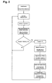
- Fig.2 depicts the basic algorithm for the detection of power system oscillations which is explained in a strongly simplified way below. A full account on the mathematical details can be found in the article " Detection of Oscillations in Power Systems using Kalman Filtering Techniques", P. Korba, M. Larsson, C. Rehtanz, IEEE (June 2003 ).
- all parameters used for recursive calculations must be initialized and the dynamical order (n) of the discrete-time autoregressive model (where n stands for the number of parameters to be estimated) must be determined.
- the latter task can be systematically solved off-line in advance based on a given set of real measured data using well-known criteria such as AIC (Akake's Information Criterion), FPE (Final Prediction Error) or MDL (minimal description length).
- AIC Alkake's Information Criterion
- FPE Frinal Prediction Error
- MDL minimal description length
- n is the most important aspect of the use of the autoregressive model. If the order is too low, the obtained spectrum in the frequency domain will be highly smoothed, and the oscillation of interest with low-level peaks in the spectrum are dissimulated. On the other hand, if the order is too high, faked low-level peaks will be introduced in the spectrum.
- Sampling a new measurement stands for storing the new measured data in a buffer having only the length n.
- the next step of the algorithm consists of solving recursively the optimal identification problem of the model parameters a i by means of the adaptive Kalman-Filter.
- the most suitable conversion of the estimated linear discrete-time autoregressive model of the power system to a continuous-time model is Tustin's approximation.
- This choice has the advantage that the left half-s-plane (s being the time continuous variable) is transferred into the unit-disc in z-plane (z being the time discrete variable of the time discrete model).
- the most important oscillations to detect regarding stability are the dominant ones. They are characterized by complex eigenvalues having the largest real part of all. Hence, in this step, the dominant eigenvalue pair is searched for in the set of all n eigenvalues calculated in the previous step.
- a negative or very small positive damping indicates that the system is (getting) unstable. This fact together with the corresponding values of frequency and damping are displayed to the operator.
- a simple signalization based on a comparison of the actual calculated value with a threshold value can be included.
- modal analysis was applied to identify a suitable system quantity corresponding to a signal of the phase angle of the current at a particular location.
- Fig.3 shows, as a function of time, the damping (top) and frequency (bottom) of a system oscillation. Every 100 sec, a transmission line was connected or disconnected, giving rise to a change in the oscillation pattern. Horizontal lines represent an alarm threshold 30 and are connected to some alarm mechanism.
- the incoming measured signal may temporarily consist of noise with a mean value close to zero rather than of realistic data. It is then advantageous to consider all measurements to equal exactly zero, otherwise the dominant frequency of the noise is estimated rather than the dominant frequency of the measured signal. Based on an observation of the average signal power, a threshold is fixed, and the estimated parameters will be frozen (not up-dated) if the actual signal power is lower than the threshold.
- the detection of electromechanical oscillations in power systems and the estimation of their parameters is based on a linear time-varying model.
- the parameters of the linear model are on-line adapted by means of Kalman filtering techniques to approximate the measured signal y (representing the behaviour of the power system) optimally in the sense of a quadratic criterion.
- the estimated model parameters are then the basis for the calculation of parameters of the oscillations.
- Adaptive algorithms are based on a recursive calculation of the estimated parameter vector for each time-step based on the new value of the measured signal and the old values of the estimated parameters.
Landscapes
- Engineering & Computer Science (AREA)
- Power Engineering (AREA)
- Supply And Distribution Of Alternating Current (AREA)
- Measurement Of Mechanical Vibrations Or Ultrasonic Waves (AREA)
- Air Bags (AREA)
Claims (10)
- Verfahren zum Detektieren elektromechanischer Schwingungen in einem Stromübertragungssystem (1), wobeia) eine dynamische Systemgröße (y) des Stromübertragungssystems (1) wiederholt gemessen wird, und eine Serie von gemessenen Werten (y1, y2, ...) der dynamischen Systemgröße (y) erzeugt wird,b) Modellparameter (a1, a2, ...) eines Diskretzeitmodells endlicher Ordnung des Stromübertragungssystems (1) anhand der Serie (y1, y2, ...) geschätzt werden,c) Frequenz und Dämpfung (ν,ξ) eines elektromechanischen Schwingungsmodus des Stromübertragungssystems (1) von den Modellparametern (a1, a2, ...) abgeleitet werden,
dadurch gekennzeichnet, dassd) die Modellparameter (a1, a2, ...) rekursiv jedes Mal dann aktualisiert werden, wenn ein neuer Wert (yk) der dynamischen Systemgröße (y) gemessen wird. - Verfahren nach Anspruch 1, dadurch gekennzeichnet, dass das Diskretzeitmodell endlicher Ordnung des Stromübertragungssystems ein lineares autoregressives Modell endlicher Ordnung ist.
- Verfahren nach Anspruch 2, dadurch gekennzeichnet, dass ein adaptives Kalman-Filter benutzt wird, um die Modellparameter (a1, a2, ...) des linearen autoregressiven Modells zu schätzen.
- Verfahren nach Anspruch 3, dadurch gekennzeichnet, dass eine Kovarianzmatrix K(k) des adaptiven Kalman-Filters symmetrisch ist.
- Verfahren nach Anspruch 2, dadurch gekennzeichnet, dass eine bilineare oder Tustin-Transformation benutzt wird, um das lineare autoregressive Diskretzeitmodell in ein Kontinuitätszeitmodell umzuwandeln.
- Verfahren nach einem der Ansprüche 1 bis 5, dadurch gekennzeichnet, dass die Frequenz und die Dämpfung (ν,ξ) des Schwingungsmodus mit der geringsten Dämpfung regelmäßig aktualisiert und einem Betreiber angezeigt werden.
- Verfahren nach Anspruch 1, dadurch gekennzeichnet, dass die Frequenz und die Dämpfung (ν,ξ) der Schwingungen weniger häufig von den Modellparametern (a1, a2, ...) abgeleitet werden, als die Modellparameter (a1, a2, ...) aktualisiert werden.
- Verfahren nach einem der vorangehenden Ansprüche, dadurch gekennzeichnet, dass die dynamische Systemgröße (y) ein Phasorsignal mit Zeitstempel ist, das von einem Phasenmessmodul (20) bereitgestellt wird.
- Elektrisches Stromübertragungssystem (1), das Mittel zum Detektieren elektromechanischer Schwingungen des Stromübertragungssystems (1) aufweist, aufweisend:a) Mittel (20) zum wiederholten Messen einer dynamischen Systemgröße (y) des Stromübertragungssystems (1), und zum Erzeugen einer Serie gemessener Werte (y1, y2, ...) der dynamischen Systemgröße (y),b) Mittel zum Schätzen, anhand der Serie (y1, y2, ...), von Modellparametern (a1, a2, ...) eines Diskretzeitmodells endlicher Ordnung des Stromübertragungssystems (1),c) Mittel zum Ableiten der Frequenz und der Dämpfung (ν,ξ) eines elektromechanischen Schwingungsmodus des Stromübertragungssystems (1) von den Modellparametern (a1, a2,...) ,
dadurch gekennzeichnet, dass die Mittel zum Detektieren elektromechanischer Schwingungen des Stromübertragungssystems (1) Folgendes aufweisen:d) Mittel zum rekursiven Aktualisieren der Modellparameter (a1, a2, ...) jedes Mal dann, wenn ein neuer Wert (yk) der dynamischen Systemgröße (y) gemessen wird. - Computerprogrammprodukt zum Detektieren elektromechanischer Schwingungen in elektrischen Stromübertragungssystemen, das in einen internen Speicher eines digitalen Computers geladen werden kann, aufweisend Computerprogrammcodemittel, um den Computer dann, wenn das Programm in den internen Speicher geladen wird, dazu zu veranlassen, das Verfahren zum Detektieren elektromechanischer Schwingungen nach einem der Ansprüche 1 bis 8 auszuführen.
Priority Applications (6)
| Application Number | Priority Date | Filing Date | Title |
|---|---|---|---|
| AT03405450T ATE382975T1 (de) | 2003-06-21 | 2003-06-21 | Ermittlung elektromechanischer schwingungen in stromversorgungssystemen |
| EP03405450A EP1489714B1 (de) | 2003-06-21 | 2003-06-21 | Ermittlung elektromechanischer Schwingungen in Stromversorgungssystemen |
| ES03405450T ES2299678T3 (es) | 2003-06-21 | 2003-06-21 | Metodo para detectar oscilaciones electromecanicas en sistema de potencia. |
| SI200331168T SI1489714T1 (sl) | 2003-06-21 | 2003-06-21 | Zaznavanje elektromehanskih nihanj v močnostnih sistemih |
| DE60318408T DE60318408T2 (de) | 2003-06-21 | 2003-06-21 | Ermittlung elektromechanischer Schwingungen in Stromversorgungssystemen |
| US10/871,685 US7149637B2 (en) | 2003-06-21 | 2004-06-18 | Detecting electromechanical oscillations in power systems |
Applications Claiming Priority (1)
| Application Number | Priority Date | Filing Date | Title |
|---|---|---|---|
| EP03405450A EP1489714B1 (de) | 2003-06-21 | 2003-06-21 | Ermittlung elektromechanischer Schwingungen in Stromversorgungssystemen |
Publications (2)
| Publication Number | Publication Date |
|---|---|
| EP1489714A1 EP1489714A1 (de) | 2004-12-22 |
| EP1489714B1 true EP1489714B1 (de) | 2008-01-02 |
Family
ID=33396095
Family Applications (1)
| Application Number | Title | Priority Date | Filing Date |
|---|---|---|---|
| EP03405450A Expired - Lifetime EP1489714B1 (de) | 2003-06-21 | 2003-06-21 | Ermittlung elektromechanischer Schwingungen in Stromversorgungssystemen |
Country Status (6)
| Country | Link |
|---|---|
| US (1) | US7149637B2 (de) |
| EP (1) | EP1489714B1 (de) |
| AT (1) | ATE382975T1 (de) |
| DE (1) | DE60318408T2 (de) |
| ES (1) | ES2299678T3 (de) |
| SI (1) | SI1489714T1 (de) |
Cited By (1)
| Publication number | Priority date | Publication date | Assignee | Title |
|---|---|---|---|---|
| WO2013087122A1 (de) | 2011-12-16 | 2013-06-20 | Siemens Aktiengesellschaft | Verfahren zum erzeugen eines eine pendelung in einem elektrischen energieversorgungsnetz angebenden signals |
Families Citing this family (55)
| Publication number | Priority date | Publication date | Assignee | Title |
|---|---|---|---|---|
| WO2005015366A2 (en) | 2003-08-08 | 2005-02-17 | Electric Power Group, Llc | Real-time performance monitoring and management system |
| EP1737098A1 (de) | 2005-06-24 | 2006-12-27 | Abb Research Ltd. | Dämpfung von elektromagnetischen Schwingungen in einem Leistungsystem |
| EP1780619A1 (de) * | 2005-10-31 | 2007-05-02 | Abb Research Ltd. | Initialisierung einer Bewertung von dynamischen Modellparametern |
| EP1783499A1 (de) | 2005-11-08 | 2007-05-09 | ABB Technology AG | Verfahren und Vorrichtung zur Überprüfung der Genauigkeit von Berechnungen zur Zustandsschätzung |
| ATE445926T1 (de) * | 2006-05-19 | 2009-10-15 | Abb Research Ltd | Fehlererkennung in stromsystemen |
| EP1887673A1 (de) * | 2006-08-11 | 2008-02-13 | Abb Research Ltd. | Parameterschätzverfahren eines thermischen Modells einer Stromleitung |
| US7494271B2 (en) * | 2007-02-05 | 2009-02-24 | Abb Research Ltd. | Power-line sag calculation by way of power-system state estimation |
| US9702923B2 (en) | 2007-09-17 | 2017-07-11 | Pål Even Gaarder | Method and apparatus for monitoring electric power transmission, disturbances and forecasts |
| US10598705B2 (en) * | 2007-09-17 | 2020-03-24 | Live Power Intelligence Company Na, Llc | Method and apparatus for monitoring power transmission |
| US8498832B2 (en) * | 2007-09-28 | 2013-07-30 | Schweitzer Engineering Laboratories Inc. | Method and device for assessing and monitoring voltage security in a power system |
| US7987059B2 (en) * | 2007-10-09 | 2011-07-26 | Schweitzer Engineering Laboratories, Inc | Real-time power system oscillation detection using modal analysis |
| US8892375B2 (en) | 2008-05-09 | 2014-11-18 | Accenture Global Services Limited | Power grid outage and fault condition management |
| US7979220B2 (en) * | 2008-08-21 | 2011-07-12 | Abb Research Ltd. | System and method for monitoring power damping compliance of a power generation unit |
| CN101685966B (zh) * | 2008-09-27 | 2012-07-04 | 国家电力调度通信中心 | 一种低频振荡综合分析的方法及其系统 |
| MY163732A (en) * | 2008-12-15 | 2017-10-13 | Accenture Global Services Ltd | Power grid outage and fault condition management |
| CN101661069B (zh) * | 2009-09-25 | 2011-07-20 | 北京四方继保自动化股份有限公司 | 不依赖状态矩阵的弱可观非pmu测点动态过程实时估计方法 |
| EP2312506A1 (de) | 2009-10-16 | 2011-04-20 | ABB Technology AG | Verfahren und Vorrichtung auf Computerbasis zur automatischen Bereitstellung einer Vorhersage über einen zukünftigen Energiebedarf an eine Energiequelle |
| WO2011050827A1 (de) * | 2009-10-29 | 2011-05-05 | Siemens Aktiengesellschaft | Überwachung einer energieübertragungs- oder energieverteilungsnanlage |
| EP2325968A1 (de) | 2009-11-18 | 2011-05-25 | ABB Research Ltd. | Abstimmung einer Einheit zur Dämpfung von Leistungsschwingungen |
| CN102870308B (zh) * | 2010-03-17 | 2016-01-20 | Abb研究有限公司 | 增强输电系统的广域控制可靠性 |
| CN102055201B (zh) * | 2010-12-09 | 2012-11-14 | 北京四方继保自动化股份有限公司 | 基于微扰动信号振荡模式辨识的电力系统低频振荡机理分析方法 |
| US9350163B2 (en) | 2011-10-19 | 2016-05-24 | General Electric Company | Inter-area oscillation detection |
| US9293949B2 (en) | 2012-02-06 | 2016-03-22 | Montana Tech Of The University Of Montana | Electric power grid signal processing methods, oscillatory mode estimation methods and mode shape estimation methods |
| RU2521768C2 (ru) * | 2012-07-20 | 2014-07-10 | Открытое Акционерное Общество "Системный Оператор Единой Энергетической Системы" | Способ выявления источника синхронных колебаний |
| EP2713172B1 (de) | 2012-09-26 | 2019-05-29 | Rheinisch-Westfälisch-Technische Hochschule Aachen | Messvorrichtung für Stromverteilungsnetze |
| CN102930077B (zh) * | 2012-09-27 | 2014-10-29 | 华北电力大学 | 一种基于改进型目标函数的抗差励磁系统参数辨识方法 |
| US9864820B2 (en) * | 2012-10-03 | 2018-01-09 | Operation Technology, Inc. | Generator dynamic model parameter estimation and tuning using online data and subspace state space model |
| CN102928695A (zh) * | 2012-10-18 | 2013-02-13 | 中国电力科学研究院 | 基于直线法判别负阻尼振荡与强迫振荡的方法 |
| RU2513874C1 (ru) * | 2012-11-02 | 2014-04-20 | Открытое Акционерное Общество "Системный Оператор Единой Энергетической Системы" | Способ мониторинга переходных режимов в электроэнергетической системе и устройство для его реализации |
| AU2014216126A1 (en) | 2013-02-14 | 2015-08-06 | Schweitzer Engineering Laboratories, Inc. | Detection of poorly damped oscillation modes |
| CN103473401B (zh) * | 2013-08-29 | 2016-09-21 | 国家电网公司 | 基于psasp的风电机组模型及其功率扰动仿真校验方法 |
| CN103530816A (zh) * | 2013-10-10 | 2014-01-22 | 国家电网公司 | 面向供电可靠性的配电网可靠性二次优化评估模型 |
| CN103646146B (zh) * | 2013-12-20 | 2017-03-29 | 武汉大学 | 基于改进原子分解参数辨识的svc控制器设计方法 |
| EP2891904A1 (de) | 2014-01-07 | 2015-07-08 | ABB Technology AB | Sonneneinstrahlungsvorhersage |
| US9590550B2 (en) | 2014-01-16 | 2017-03-07 | General Electric Company | Systems and methods for adaptive control of excitation and generator systems |
| EP2978095A1 (de) | 2014-07-23 | 2016-01-27 | ABB Technology AG | Stromversorgungssystembetrieb |
| CN104898415B (zh) * | 2015-03-31 | 2017-09-19 | 北京四方继保自动化股份有限公司 | 一种基于低通滤波的发电机组转动惯量参数的在线辨识方法 |
| CN105140957B (zh) * | 2015-08-20 | 2017-10-10 | 华北电力大学 | 基于风电场和光伏电站聚合模型的机电振荡模式估算方法 |
| CN105866633B (zh) * | 2016-05-30 | 2018-06-19 | 上海交通大学 | 基于波权重的输电线路故障电流行波波形的重现方法 |
| EP3252482B1 (de) * | 2016-06-01 | 2021-02-17 | Siemens Aktiengesellschaft | Verfahren und leitstelleneinrichtung zum bestimmen eines phasenwinkels einer leistungspendelung in einem elektrischen energieversorgungsnetz |
| CN106169115B (zh) * | 2016-06-23 | 2020-04-14 | 西南交通大学 | 一种利用解析-数值法估算两区域电网最低频率的方法 |
| CN108090270B (zh) * | 2017-12-12 | 2020-12-22 | 华南理工大学 | 一种基于形态学滤波和盲源分离的暂态振荡参数识别方法 |
| CN108462192B (zh) * | 2018-04-28 | 2020-05-05 | 清华大学 | 电力系统宽频带振荡的模式分析方法 |
| JP7034978B2 (ja) * | 2019-03-19 | 2022-03-14 | 株式会社東芝 | 系統安定化装置 |
| CN110323741B (zh) * | 2019-07-10 | 2022-05-13 | 国网福建省电力有限公司 | 基于录波曲线的电力系统低频振荡分析与抑制方法 |
| CN110728177B (zh) * | 2019-09-02 | 2022-06-14 | 华南理工大学 | 基于双协方差随机子空间的类噪声数据低频振荡辨识方法 |
| CN112531736B (zh) * | 2020-11-24 | 2023-10-31 | 国家电网有限公司 | 一种电力系统区域间振荡抑制的广域阻尼控制器设计方法 |
| CN112366735B (zh) * | 2020-12-01 | 2022-06-07 | 合肥工业大学 | 一种基于自适应在线模型辨识的微电网二次调频方法 |
| CN113156200B (zh) * | 2020-12-14 | 2023-01-13 | 北京信息科技大学 | 一种电网低频振荡实时监测装置 |
| CN114123238B (zh) * | 2021-11-12 | 2023-09-22 | 国网江苏省电力有限公司营销服务中心 | 一种电解铝负荷参与电力系统调频的卡尔曼滤波控制方法 |
| CN114301077A (zh) * | 2021-12-29 | 2022-04-08 | 国家电网公司西南分部 | 一种电力系统负弱阻尼机组识别方法及系统 |
| CN115378122B (zh) * | 2022-04-11 | 2023-05-09 | 东南大学溧阳研究院 | 基于卡尔曼滤波的电力系统频率与惯量实时监测方法及其系统 |
| CN115357853B (zh) * | 2022-08-22 | 2023-08-04 | 河海大学 | 一种基于快速随机子空间的工程结构模态参数识别方法 |
| FR3141573A1 (fr) | 2022-10-26 | 2024-05-03 | General Electric Company | Systèmes et procédés pour un stabilisateur de système électrique (pss) adaptatif |
| CN121484964B (zh) * | 2025-10-24 | 2026-07-03 | 山东大学 | 基于相位补偿器的构网型电磁尺度致稳控制方法及系统 |
Family Cites Families (9)
| Publication number | Priority date | Publication date | Assignee | Title |
|---|---|---|---|---|
| US4051427A (en) * | 1974-10-29 | 1977-09-27 | Westinghouse Electric Corporation | Supervisory system for detecting torsional oscillation in the shaft of a rotating electro-mechanical system |
| US4741023A (en) * | 1986-12-23 | 1988-04-26 | General Electric Company | On-line test and diagnostic system for power system stabilizer |
| US5566092A (en) * | 1993-12-30 | 1996-10-15 | Caterpillar Inc. | Machine fault diagnostics system and method |
| DE19746719C1 (de) * | 1997-10-15 | 1999-05-06 | Siemens Ag | Verfahren zum Gewinnen eines eine Pendelung in einem elektrischen Energieversorgungsnetz anzeigenden Signals |
| WO1999066634A1 (de) * | 1998-06-17 | 1999-12-23 | Siemens Aktiengesellschaft | Modellbasiertes entwurfsverfahren für ein pendeldämpfungsgerät und anlage mit einem derartigen pendeldämpfungsgerät |
| DE19948694B4 (de) * | 1999-09-30 | 2006-04-06 | Siemens Ag | Verfahren zum Erzeugen von einem eine Pendelung in einem elektrischen Energievesorgungsnetz anzeigenden Signal |
| SE517714C2 (sv) * | 2000-05-31 | 2002-07-09 | Abb Ab | Nätvärnssystem för skydd av ett totalt elkraftsystems integritet mot svagt dämpade effektsvängningar, elkraftsystem innefattande ett nätvärn, systemskyddssystemförfarande, systemskyddsterminal, datorprogramprodukt samt datorläsbart medium |
| ATE369651T1 (de) * | 2001-06-22 | 2007-08-15 | Psymetrix Ltd | Verfahren zur überwachung eines hochspannungsnetzes |
| US20040102937A1 (en) * | 2002-11-21 | 2004-05-27 | Honeywell International Inc. | Energy forecasting using model parameter estimation |
-
2003
- 2003-06-21 EP EP03405450A patent/EP1489714B1/de not_active Expired - Lifetime
- 2003-06-21 AT AT03405450T patent/ATE382975T1/de not_active IP Right Cessation
- 2003-06-21 DE DE60318408T patent/DE60318408T2/de not_active Expired - Lifetime
- 2003-06-21 SI SI200331168T patent/SI1489714T1/sl unknown
- 2003-06-21 ES ES03405450T patent/ES2299678T3/es not_active Expired - Lifetime
-
2004
- 2004-06-18 US US10/871,685 patent/US7149637B2/en not_active Expired - Lifetime
Cited By (1)
| Publication number | Priority date | Publication date | Assignee | Title |
|---|---|---|---|---|
| WO2013087122A1 (de) | 2011-12-16 | 2013-06-20 | Siemens Aktiengesellschaft | Verfahren zum erzeugen eines eine pendelung in einem elektrischen energieversorgungsnetz angebenden signals |
Also Published As
| Publication number | Publication date |
|---|---|
| ATE382975T1 (de) | 2008-01-15 |
| EP1489714A1 (de) | 2004-12-22 |
| DE60318408D1 (de) | 2008-02-14 |
| SI1489714T1 (sl) | 2008-06-30 |
| US20050187726A1 (en) | 2005-08-25 |
| DE60318408T2 (de) | 2009-01-29 |
| ES2299678T3 (es) | 2008-06-01 |
| US7149637B2 (en) | 2006-12-12 |
Similar Documents
| Publication | Publication Date | Title |
|---|---|---|
| US7149637B2 (en) | Detecting electromechanical oscillations in power systems | |
| Korba et al. | Detection of oscillations in power systems using Kalman filtering techniques | |
| RU2430457C2 (ru) | Оценка параметров тепловой модели линии электропитания | |
| US9746511B2 (en) | Estimating the locations of power system events using PMU measurements | |
| EP0873583B1 (de) | Digitales stromdifferentialsystem | |
| AU2011238726B2 (en) | Systems and method for obtaining a load model and related parameters based on load dynamics | |
| US7490013B2 (en) | Power grid failure detection system and method | |
| US8340931B2 (en) | Power grid with comparison of differences in remote phasor changes | |
| EP2962376B1 (de) | Rasterschwingungsanalyseverfahren und -vorrichtung | |
| EP2018694B1 (de) | Fehlererkennung in stromsystemen | |
| JP2003052126A (ja) | 電力ネットワークの安定性予測 | |
| US20150168465A1 (en) | Method and apparatus for electric power system distribution state estimations | |
| WO2012060883A2 (en) | Power grid failure prediction and detection | |
| CA2771380C (en) | Systems and methods for asynchronous sampling data conversion | |
| CN120294800A (zh) | 一种基于北斗同步与智能滤波的行波故障定位系统及方法 | |
| EP2654163B1 (de) | Leistungskonditioniervorrichtung, steuerungsvorrichtung für eine leistungskonditioniervorrichtung und steuerverfahren | |
| EP4429060A1 (de) | Verarbeitungsverfahren und verarbeitungssystem zur verarbeitung von in einem stromnetz erfassten messungen und system mit einem stromnetz | |
| WO2019086946A1 (en) | System and method for analyzing fault data of a power transmission network | |
| CN107782966A (zh) | 确定交流信号的频率 | |
| CN120712485A (zh) | 用于处理在电网中获取的测量的处理方法和处理系统以及包括电网的系统 | |
| EP2795759B1 (de) | Handhabung von resonanzen in einem leistungsübertragungssystem | |
| Yu et al. | Unscented trainable Kalman filter based on deep learning method considering incomplete information | |
| Khond et al. | Detection of bad data and estimation of missing parameter values using system synergism | |
| KR101664010B1 (ko) | 시각 동기화 데이터를 이용한 전력계통의 선로정수 추정방법 | |
| Moreno-Chuquen et al. | Online dynamic assessment of system stability in power systems using the unscented kalman filter |
Legal Events
| Date | Code | Title | Description |
|---|---|---|---|
| PUAI | Public reference made under article 153(3) epc to a published international application that has entered the european phase |
Free format text: ORIGINAL CODE: 0009012 |
|
| AK | Designated contracting states |
Kind code of ref document: A1 Designated state(s): AT BE BG CH CY CZ DE DK EE ES FI FR GB GR HU IE IT LI LU MC NL PT RO SE SI SK TR |
|
| AX | Request for extension of the european patent |
Extension state: AL LT LV MK |
|
| 17P | Request for examination filed |
Effective date: 20050509 |
|
| 17Q | First examination report despatched |
Effective date: 20050629 |
|
| AKX | Designation fees paid |
Designated state(s): AT BE BG CH CY CZ DE DK EE ES FI FR GB GR HU IE IT LI LU MC NL PT RO SE SI SK TR |
|
| 17Q | First examination report despatched |
Effective date: 20050629 |
|
| GRAP | Despatch of communication of intention to grant a patent |
Free format text: ORIGINAL CODE: EPIDOSNIGR1 |
|
| GRAS | Grant fee paid |
Free format text: ORIGINAL CODE: EPIDOSNIGR3 |
|
| GRAA | (expected) grant |
Free format text: ORIGINAL CODE: 0009210 |
|
| AK | Designated contracting states |
Kind code of ref document: B1 Designated state(s): AT BE BG CH CY CZ DE DK EE ES FI FR GB GR HU IE IT LI LU MC NL PT RO SE SI SK TR |
|
| REG | Reference to a national code |
Ref country code: GB Ref legal event code: FG4D |
|
| REG | Reference to a national code |
Ref country code: IE Ref legal event code: FG4D |
|
| REG | Reference to a national code |
Ref country code: CH Ref legal event code: EP |
|
| REF | Corresponds to: |
Ref document number: 60318408 Country of ref document: DE Date of ref document: 20080214 Kind code of ref document: P |
|
| REG | Reference to a national code |
Ref country code: RO Ref legal event code: EPE |
|
| REG | Reference to a national code |
Ref country code: SE Ref legal event code: TRGR |
|
| PG25 | Lapsed in a contracting state [announced via postgrant information from national office to epo] |
Ref country code: NL Free format text: LAPSE BECAUSE OF FAILURE TO SUBMIT A TRANSLATION OF THE DESCRIPTION OR TO PAY THE FEE WITHIN THE PRESCRIBED TIME-LIMIT Effective date: 20080102 |
|
| REG | Reference to a national code |
Ref country code: ES Ref legal event code: FG2A Ref document number: 2299678 Country of ref document: ES Kind code of ref document: T3 |
|
| NLV1 | Nl: lapsed or annulled due to failure to fulfill the requirements of art. 29p and 29m of the patents act | ||
| REG | Reference to a national code |
Ref country code: HU Ref legal event code: AG4A Ref document number: E003115 Country of ref document: HU |
|
| PG25 | Lapsed in a contracting state [announced via postgrant information from national office to epo] |
Ref country code: LI Free format text: LAPSE BECAUSE OF FAILURE TO SUBMIT A TRANSLATION OF THE DESCRIPTION OR TO PAY THE FEE WITHIN THE PRESCRIBED TIME-LIMIT Effective date: 20080102 Ref country code: FI Free format text: LAPSE BECAUSE OF FAILURE TO SUBMIT A TRANSLATION OF THE DESCRIPTION OR TO PAY THE FEE WITHIN THE PRESCRIBED TIME-LIMIT Effective date: 20080102 Ref country code: CH Free format text: LAPSE BECAUSE OF FAILURE TO SUBMIT A TRANSLATION OF THE DESCRIPTION OR TO PAY THE FEE WITHIN THE PRESCRIBED TIME-LIMIT Effective date: 20080102 |
|
| REG | Reference to a national code |
Ref country code: CH Ref legal event code: PL |
|
| PG25 | Lapsed in a contracting state [announced via postgrant information from national office to epo] |
Ref country code: AT Free format text: LAPSE BECAUSE OF FAILURE TO SUBMIT A TRANSLATION OF THE DESCRIPTION OR TO PAY THE FEE WITHIN THE PRESCRIBED TIME-LIMIT Effective date: 20080102 |
|
| PG25 | Lapsed in a contracting state [announced via postgrant information from national office to epo] |
Ref country code: BE Free format text: LAPSE BECAUSE OF FAILURE TO SUBMIT A TRANSLATION OF THE DESCRIPTION OR TO PAY THE FEE WITHIN THE PRESCRIBED TIME-LIMIT Effective date: 20080102 Ref country code: PT Free format text: LAPSE BECAUSE OF FAILURE TO SUBMIT A TRANSLATION OF THE DESCRIPTION OR TO PAY THE FEE WITHIN THE PRESCRIBED TIME-LIMIT Effective date: 20080602 |
|
| PG25 | Lapsed in a contracting state [announced via postgrant information from national office to epo] |
Ref country code: SK Free format text: LAPSE BECAUSE OF FAILURE TO SUBMIT A TRANSLATION OF THE DESCRIPTION OR TO PAY THE FEE WITHIN THE PRESCRIBED TIME-LIMIT Effective date: 20080102 Ref country code: DK Free format text: LAPSE BECAUSE OF FAILURE TO SUBMIT A TRANSLATION OF THE DESCRIPTION OR TO PAY THE FEE WITHIN THE PRESCRIBED TIME-LIMIT Effective date: 20080102 |
|
| PLBE | No opposition filed within time limit |
Free format text: ORIGINAL CODE: 0009261 |
|
| STAA | Information on the status of an ep patent application or granted ep patent |
Free format text: STATUS: NO OPPOSITION FILED WITHIN TIME LIMIT |
|
| 26N | No opposition filed |
Effective date: 20081003 |
|
| PG25 | Lapsed in a contracting state [announced via postgrant information from national office to epo] |
Ref country code: MC Free format text: LAPSE BECAUSE OF NON-PAYMENT OF DUE FEES Effective date: 20080630 |
|
| PG25 | Lapsed in a contracting state [announced via postgrant information from national office to epo] |
Ref country code: CY Free format text: LAPSE BECAUSE OF FAILURE TO SUBMIT A TRANSLATION OF THE DESCRIPTION OR TO PAY THE FEE WITHIN THE PRESCRIBED TIME-LIMIT Effective date: 20080102 |
|
| PG25 | Lapsed in a contracting state [announced via postgrant information from national office to epo] |
Ref country code: LU Free format text: LAPSE BECAUSE OF NON-PAYMENT OF DUE FEES Effective date: 20080621 |
|
| PG25 | Lapsed in a contracting state [announced via postgrant information from national office to epo] |
Ref country code: TR Free format text: LAPSE BECAUSE OF FAILURE TO SUBMIT A TRANSLATION OF THE DESCRIPTION OR TO PAY THE FEE WITHIN THE PRESCRIBED TIME-LIMIT Effective date: 20080102 |
|
| PG25 | Lapsed in a contracting state [announced via postgrant information from national office to epo] |
Ref country code: GR Free format text: LAPSE BECAUSE OF FAILURE TO SUBMIT A TRANSLATION OF THE DESCRIPTION OR TO PAY THE FEE WITHIN THE PRESCRIBED TIME-LIMIT Effective date: 20080403 |
|
| PGFP | Annual fee paid to national office [announced via postgrant information from national office to epo] |
Ref country code: ES Payment date: 20150626 Year of fee payment: 13 Ref country code: GB Payment date: 20150618 Year of fee payment: 13 Ref country code: EE Payment date: 20150611 Year of fee payment: 13 Ref country code: SE Payment date: 20150618 Year of fee payment: 13 Ref country code: BG Payment date: 20150611 Year of fee payment: 13 |
|
| PGFP | Annual fee paid to national office [announced via postgrant information from national office to epo] |
Ref country code: IT Payment date: 20150622 Year of fee payment: 13 Ref country code: HU Payment date: 20150618 Year of fee payment: 13 Ref country code: IE Payment date: 20150619 Year of fee payment: 13 |
|
| REG | Reference to a national code |
Ref country code: FR Ref legal event code: PLFP Year of fee payment: 14 |
|
| PGFP | Annual fee paid to national office [announced via postgrant information from national office to epo] |
Ref country code: CZ Payment date: 20160620 Year of fee payment: 14 |
|
| PGFP | Annual fee paid to national office [announced via postgrant information from national office to epo] |
Ref country code: SI Payment date: 20160525 Year of fee payment: 14 Ref country code: RO Payment date: 20160601 Year of fee payment: 14 |
|
| REG | Reference to a national code |
Ref country code: EE Ref legal event code: MM4A Ref document number: E002047 Country of ref document: EE Effective date: 20160630 |
|
| REG | Reference to a national code |
Ref country code: SE Ref legal event code: EUG |
|
| PG25 | Lapsed in a contracting state [announced via postgrant information from national office to epo] |
Ref country code: SE Free format text: LAPSE BECAUSE OF NON-PAYMENT OF DUE FEES Effective date: 20160622 |
|
| GBPC | Gb: european patent ceased through non-payment of renewal fee |
Effective date: 20160621 |
|
| REG | Reference to a national code |
Ref country code: IE Ref legal event code: MM4A |
|
| PG25 | Lapsed in a contracting state [announced via postgrant information from national office to epo] |
Ref country code: HU Free format text: LAPSE BECAUSE OF NON-PAYMENT OF DUE FEES Effective date: 20160622 Ref country code: EE Free format text: LAPSE BECAUSE OF NON-PAYMENT OF DUE FEES Effective date: 20160630 |
|
| PG25 | Lapsed in a contracting state [announced via postgrant information from national office to epo] |
Ref country code: BG Free format text: LAPSE BECAUSE OF NON-PAYMENT OF DUE FEES Effective date: 20170131 Ref country code: IE Free format text: LAPSE BECAUSE OF NON-PAYMENT OF DUE FEES Effective date: 20160621 Ref country code: GB Free format text: LAPSE BECAUSE OF NON-PAYMENT OF DUE FEES Effective date: 20160621 |
|
| REG | Reference to a national code |
Ref country code: FR Ref legal event code: PLFP Year of fee payment: 15 |
|
| PG25 | Lapsed in a contracting state [announced via postgrant information from national office to epo] |
Ref country code: IT Free format text: LAPSE BECAUSE OF NON-PAYMENT OF DUE FEES Effective date: 20160621 |
|
| PG25 | Lapsed in a contracting state [announced via postgrant information from national office to epo] |
Ref country code: RO Free format text: LAPSE BECAUSE OF NON-PAYMENT OF DUE FEES Effective date: 20170621 Ref country code: CZ Free format text: LAPSE BECAUSE OF NON-PAYMENT OF DUE FEES Effective date: 20170621 |
|
| REG | Reference to a national code |
Ref country code: SI Ref legal event code: KO00 Effective date: 20180213 |
|
| PG25 | Lapsed in a contracting state [announced via postgrant information from national office to epo] |
Ref country code: SI Free format text: LAPSE BECAUSE OF NON-PAYMENT OF DUE FEES Effective date: 20170622 Ref country code: ES Free format text: LAPSE BECAUSE OF NON-PAYMENT OF DUE FEES Effective date: 20160622 |
|
| REG | Reference to a national code |
Ref country code: FR Ref legal event code: PLFP Year of fee payment: 16 |
|
| REG | Reference to a national code |
Ref country code: ES Ref legal event code: FD2A Effective date: 20181203 |
|
| REG | Reference to a national code |
Ref country code: DE Ref legal event code: R081 Ref document number: 60318408 Country of ref document: DE Owner name: HITACHI ENERGY SWITZERLAND AG, CH Free format text: FORMER OWNER: ABB RESEARCH LTD., ZUERICH, CH Ref country code: DE Ref legal event code: R082 Ref document number: 60318408 Country of ref document: DE Representative=s name: ZIMMERMANN & PARTNER PATENTANWAELTE MBB, DE Ref country code: DE Ref legal event code: R081 Ref document number: 60318408 Country of ref document: DE Owner name: ABB SCHWEIZ AG, CH Free format text: FORMER OWNER: ABB RESEARCH LTD., ZUERICH, CH Ref country code: DE Ref legal event code: R081 Ref document number: 60318408 Country of ref document: DE Owner name: ABB POWER GRIDS SWITZERLAND AG, CH Free format text: FORMER OWNER: ABB RESEARCH LTD., ZUERICH, CH Ref country code: DE Ref legal event code: R082 Ref document number: 60318408 Country of ref document: DE Representative=s name: DENNEMEYER & ASSOCIATES S.A., DE |
|
| REG | Reference to a national code |
Ref country code: DE Ref legal event code: R081 Ref document number: 60318408 Country of ref document: DE Owner name: HITACHI ENERGY SWITZERLAND AG, CH Free format text: FORMER OWNER: ABB SCHWEIZ AG, BADEN, CH Ref country code: DE Ref legal event code: R082 Ref document number: 60318408 Country of ref document: DE Representative=s name: DENNEMEYER & ASSOCIATES S.A., DE Ref country code: DE Ref legal event code: R081 Ref document number: 60318408 Country of ref document: DE Owner name: ABB POWER GRIDS SWITZERLAND AG, CH Free format text: FORMER OWNER: ABB SCHWEIZ AG, BADEN, CH |
|
| REG | Reference to a national code |
Ref country code: DE Ref legal event code: R081 Ref document number: 60318408 Country of ref document: DE Owner name: HITACHI ENERGY SWITZERLAND AG, CH Free format text: FORMER OWNER: ABB POWER GRIDS SWITZERLAND AG, BADEN, CH |
|
| PGFP | Annual fee paid to national office [announced via postgrant information from national office to epo] |
Ref country code: DE Payment date: 20220620 Year of fee payment: 20 |
|
| PGFP | Annual fee paid to national office [announced via postgrant information from national office to epo] |
Ref country code: FR Payment date: 20220628 Year of fee payment: 20 |
|
| REG | Reference to a national code |
Ref country code: DE Ref legal event code: R071 Ref document number: 60318408 Country of ref document: DE |
|
| P01 | Opt-out of the competence of the unified patent court (upc) registered |
Effective date: 20230527 |