EP1489768A2 - Optischer Add/Drop-Multiplexer mit Zirkulatoren und Reflektoren - Google Patents
Optischer Add/Drop-Multiplexer mit Zirkulatoren und Reflektoren Download PDFInfo
- Publication number
- EP1489768A2 EP1489768A2 EP04011559A EP04011559A EP1489768A2 EP 1489768 A2 EP1489768 A2 EP 1489768A2 EP 04011559 A EP04011559 A EP 04011559A EP 04011559 A EP04011559 A EP 04011559A EP 1489768 A2 EP1489768 A2 EP 1489768A2
- Authority
- EP
- European Patent Office
- Prior art keywords
- port
- channel
- circulator
- reflector
- drop multiplexer
- Prior art date
- Legal status (The legal status is an assumption and is not a legal conclusion. Google has not performed a legal analysis and makes no representation as to the accuracy of the status listed.)
- Withdrawn
Links
Images


Classifications
-
- H—ELECTRICITY
- H04—ELECTRIC COMMUNICATION TECHNIQUE
- H04B—TRANSMISSION
- H04B10/00—Transmission systems employing electromagnetic waves other than radio-waves, e.g. infrared, visible or ultraviolet light, or employing corpuscular radiation, e.g. quantum communication
- H04B10/25—Arrangements specific to fibre transmission
- H04B10/2581—Multimode transmission
-
- G—PHYSICS
- G02—OPTICS
- G02B—OPTICAL ELEMENTS, SYSTEMS OR APPARATUS
- G02B6/00—Light guides; Structural details of arrangements comprising light guides and other optical elements, e.g. couplings
- G02B6/10—Light guides; Structural details of arrangements comprising light guides and other optical elements, e.g. couplings of the optical waveguide type
- G02B6/12—Light guides; Structural details of arrangements comprising light guides and other optical elements, e.g. couplings of the optical waveguide type of the integrated circuit kind
- G02B6/12007—Light guides; Structural details of arrangements comprising light guides and other optical elements, e.g. couplings of the optical waveguide type of the integrated circuit kind forming wavelength selective elements, e.g. multiplexer, demultiplexer
- G02B6/12009—Light guides; Structural details of arrangements comprising light guides and other optical elements, e.g. couplings of the optical waveguide type of the integrated circuit kind forming wavelength selective elements, e.g. multiplexer, demultiplexer comprising arrayed waveguide grating [AWG] devices, i.e. with a phased array of waveguides
- G02B6/12019—Light guides; Structural details of arrangements comprising light guides and other optical elements, e.g. couplings of the optical waveguide type of the integrated circuit kind forming wavelength selective elements, e.g. multiplexer, demultiplexer comprising arrayed waveguide grating [AWG] devices, i.e. with a phased array of waveguides characterised by the optical interconnection to or from the AWG devices, e.g. integration or coupling with lasers or photodiodes
- G02B6/12021—Comprising cascaded AWG devices; AWG multipass configuration; Plural AWG devices integrated on a single chip
-
- G—PHYSICS
- G02—OPTICS
- G02B—OPTICAL ELEMENTS, SYSTEMS OR APPARATUS
- G02B6/00—Light guides; Structural details of arrangements comprising light guides and other optical elements, e.g. couplings
- G02B6/24—Coupling light guides
- G02B6/26—Optical coupling means
- G02B6/28—Optical coupling means having data bus means, i.e. plural waveguides interconnected and providing an inherently bidirectional system by mixing and splitting signals
- G02B6/293—Optical coupling means having data bus means, i.e. plural waveguides interconnected and providing an inherently bidirectional system by mixing and splitting signals with wavelength selective means
- G02B6/29304—Optical coupling means having data bus means, i.e. plural waveguides interconnected and providing an inherently bidirectional system by mixing and splitting signals with wavelength selective means operating by diffraction, e.g. grating
- G02B6/29316—Light guides comprising a diffractive element, e.g. grating in or on the light guide such that diffracted light is confined in the light guide
- G02B6/29317—Light guides of the optical fibre type
- G02B6/29319—With a cascade of diffractive elements or of diffraction operations
- G02B6/2932—With a cascade of diffractive elements or of diffraction operations comprising a directional router, e.g. directional coupler, circulator
-
- G—PHYSICS
- G02—OPTICS
- G02B—OPTICAL ELEMENTS, SYSTEMS OR APPARATUS
- G02B6/00—Light guides; Structural details of arrangements comprising light guides and other optical elements, e.g. couplings
- G02B6/24—Coupling light guides
- G02B6/26—Optical coupling means
- G02B6/28—Optical coupling means having data bus means, i.e. plural waveguides interconnected and providing an inherently bidirectional system by mixing and splitting signals
- G02B6/293—Optical coupling means having data bus means, i.e. plural waveguides interconnected and providing an inherently bidirectional system by mixing and splitting signals with wavelength selective means
- G02B6/29379—Optical coupling means having data bus means, i.e. plural waveguides interconnected and providing an inherently bidirectional system by mixing and splitting signals with wavelength selective means characterised by the function or use of the complete device
- G02B6/2938—Optical coupling means having data bus means, i.e. plural waveguides interconnected and providing an inherently bidirectional system by mixing and splitting signals with wavelength selective means characterised by the function or use of the complete device for multiplexing or demultiplexing, i.e. combining or separating wavelengths, e.g. 1xN, NxM
- G02B6/29382—Optical coupling means having data bus means, i.e. plural waveguides interconnected and providing an inherently bidirectional system by mixing and splitting signals with wavelength selective means characterised by the function or use of the complete device for multiplexing or demultiplexing, i.e. combining or separating wavelengths, e.g. 1xN, NxM including at least adding or dropping a signal, i.e. passing the majority of signals
- G02B6/29383—Adding and dropping
-
- H—ELECTRICITY
- H04—ELECTRIC COMMUNICATION TECHNIQUE
- H04B—TRANSMISSION
- H04B10/00—Transmission systems employing electromagnetic waves other than radio-waves, e.g. infrared, visible or ultraviolet light, or employing corpuscular radiation, e.g. quantum communication
-
- H—ELECTRICITY
- H04—ELECTRIC COMMUNICATION TECHNIQUE
- H04J—MULTIPLEX COMMUNICATION
- H04J14/00—Optical multiplex systems
- H04J14/02—Wavelength-division multiplex systems
- H04J14/0201—Add-and-drop multiplexing
- H04J14/0215—Architecture aspects
- H04J14/0216—Bidirectional architectures
Definitions
- the present invention relates to a wavelength division multiplexing system, and more particularly, to an optical add/drop multiplexer (ADM) for adding or dropping a predetermined channel with respect to a multiplexed optical signal.
- ADM optical add/drop multiplexer
- WDM wavelength division multiplexing
- an ADM typically includes a pair of wavelength division multiplexers/demultiplexers, and a plurality of optical switches.
- an arrayed-waveguide grating AMG
- ADM arrayed-waveguide grating
- Fig. 1 is a schematic diagram illustrating the configuration of a conventional ADM.
- the ADM includes two circulators 120,140, each connected to an optical fiber 110 and having a plurality of ports.
- the ADM also includes n fiber Bragg gratings (FBGs) 131 to 133, and two wavelength division multiplexers/demultiplexers 150,160.
- FBGs fiber Bragg gratings
- FBGs fiber Bragg gratings
- m-th port is designated by "m” in Fig. 1 while being designated, in the following description, by a reference numeral "###m", for easy understanding of the description.
- Multiplexed optical signals respectively input to and output from the ADM have a plurality of channels with different wavelengths. For example, the n-th channel ⁇ n of an input or output multiplexed optical signal has an n-th wavelength.
- the first circulator 120 has three ports 1201 to 1203.
- the first circulating circulator 120 operates to output an optical signal, inputted to a higher-order port thereof, to a lower-order port thereof arranged adjacent to the higher-order port.
- the first circulating circulator 120 outputs an optical signal, input at the first port 1201, to its second port 1202
- the first circulator 120 also outputs a channel, input at the second port 1202, to the third port 1203.
- the n FBGs 131 to 133 are connected between the second ports 1202,1402 of the two circulators 120,140.
- each of the n FBGs 131 to 133 reflect the channel of a predetermined wavelength (ON state) while passing the channel of the predetermined wavelength (OFF state).
- the second FBG 132 reflects only the second channel ⁇ 2 in the ON state
- the n-th FBG 133 reflects only the n-th channel ⁇ n.
- the WDM1 150 has a multiplexing port (MP) 151 and n demultiplexing ports (DP) 152 to 154.
- the WDM1 150 is connected at the multiplexing port 151 to the third port 1203 of the first circulator 120.
- the WDM1 150 operates to output channels of different wavelengths, input to the multiplexing port 151, to the demultiplexing ports corresponding to respective wavelengths of the input channels. For example, the WDM1 150 outputs the second channel ⁇ 2, input to the multiplexing port 151, to the second demultiplexing port 153, while outputting the n-th channel ⁇ n, input to the multiplexing port 151, to the n-th demultiplexing port 154.
- the second circulator 140 has threeports 1401 to 1403.
- the second circulator 140 operates to output an optical signal, input to a higher-order port thereof, to a lower-order port thereof arranged adjacent to the higher-order port.
- the second circulator 140 outputs a channel, input to the first port 1401, to the second port 1402, while outputting an optical signal, input to the second port 1402, to the third port 1403.
- the WDM2 160 has a multiplexing port (MP) 161 and n demultiplexing ports (DP) 162 to 164.
- the WDM1 150 is connected at the multiplexing port 161 to the first port 1401 of the second circulator 140.
- the WDM2 160 operates to output channels of different wavelengths, input to the demultiplexing ports 162 to 164, to the multiplexing port 161.
- the first and second FBGs 131,132 are set to be in the ON state by a control unit (not shown), which also sets the remaining FBGs including the n-th FBG 133 to the OFF state.
- the first circulator 120 outputs an optical signal, input at the first port 1201, to the second port 1202 connected to the first FBG 131.
- the first FBG 131 reflects only the first one of the channels of the optical signal received from the second port 1202 of the first circulator 120, that is, the channel ⁇ 1.
- the first circulator 120 outputs the first channel ⁇ 1, input to the second port 1202, to the third port 1203 connected to the multiplexing port 151 of the WDM 150.
- the WDM1 150 outputs, to the first demultiplexing port 152, the first channel ⁇ 1 input to the multiplexing port 151.
- the optical signal passing through the n FBGs 131 to 133 is input to the second port 1402 of the second circulator 140.
- the WDM2 161 receives a second channel ⁇ 2 at the second demultiplexing port 163, and outputs the received second channel X2 to the multiplexing port 161 connected to the first port of the second circulator 160.
- the second circulator 160 outputs the second channel X2, input to the first port 1401, to the second port 1402.
- the second FBG 132 reflects the second channel ⁇ 2 inputso that the second channel ⁇ 2 is directed to the second port 1402 of the second circulator 140.
- the second circulator 140 then outputs, to the third port 1403, the second channel ⁇ 2 input to the second port 1402.
- the FBGs 131 to 133 are connected in series. Accordingly, the number of FBGs in this ADM depends on the wavelength to be processed in the ADM. For example, if it is desired to drop the first channel ⁇ 1, only one FBG, the first FBG 131, may be used since the first channel ⁇ 1 can be reflected by the first FBG 131. However, where it is desired to drop the third channel ⁇ 3, this channel is dropped after passing through the first and second FBGs 131 and 132. A similar procedure is carried out in the case of adding a desired channel. If a channel to be added or dropped passes through one FBG, as mentioned above, it undergoes optical loss.
- the channel which is subjected to an add or drop procedure, has electric power that varies depending on the wavelength thereof.
- control of each FBG is typically achieved by controlling ambient temperature or tension to be applied.
- the time required for such a control is relatively long, it is difficult to achieve a high-speed switching operation.
- an object of the invention is to provide an ADM which operates irrespective of the wavelength of a channel to be added or dropped, while being capable of achieving a high-speed operation thereof.
- Another object of the invention is to provide an ADM which has a simple configuration, while being capable of being inexpensively manufactured, as compared to conventional cases.
- the present invention provides an optical add/drop multiplexer connected to an optical fiber for transmission of a multiplexed optical signal, and adapted to add a channel to the optical signal or to drop a channel from the optical signal.
- the optical add/drop multiplexer includes a wavelength division multiplexing/demultiplexing (WDM) unit connected to the optical fiber, having input and output ports providing a path for a multiplexed optical signal.
- the WDM unit also has a plurality of demultiplexing ports respectively providing paths for demultiplexed channels.
- a plurality of add/drop multiplexer (ADM) units respectively connected to the demultiplexing ports of the WDM unit.
- Each of the ADM units including first and second circulators adapted to output a channel, input to a higher-order port thereof, to a lower-order port arranged adjacent to the higher-order port.
- the first circulator receives a channel at a second port and outputs the received channel to a third port connected to the reflector.
- the first circulator secondarily receives, at the third port, the channel from the reflector and outputs the secondarily received channel to a fourth port thereof, thereby dropping the channel
- the second circulator receives a channel at a first port and outputs the received channel to a second port connected to the reflector.
- the second circulator secondarily receives, at the second port, the channel from the reflector and outputs the secondarily received channel to a third port thereof connected to a first port of the first circulator, thereby adding the channel.
- the present invention provides an optical add/drop multiplexer connected to an optical fiber for transmission of a multiplexed optical signal, and adapted to add a channel to the optical signal or to drop a channel from the optical signal.
- the optical add/drop multiplexer includes a wavelength division multiplexing/ demultiplexing (WDM) unit connected to the optical fiber, having input and output ports providing a path for a multiplexed optical signal.
- WDM wavelength division multiplexing/ demultiplexing
- the WDM also has a plurality of demultiplexing ports respectively providing passages for demultiplexed channels.
- a plurality of add/drop multiplexer (ADM) units respectively connected to the demultiplexing ports of the WDM unit.
- Each of the ADM units including a circulator adapted to output a channel, input to a higher-order port thereof, to a lower-order port thereof arranged adjacent to the higher-order port.
- a reflector connected between two selected ports of the circulator, and adapted to pass or reflect a channel inputted thereto.
- the circulator receives a channel at a second port and outputs the received channel to a third port thereof connected to the reflector.
- the circulator also secondarily receives, at the third port, the channel from the reflector and outputs the secondarily received channel to a fourth port thereof, thereby dropping the channel.
- the circulator also receives a channel at a fifth port and outputs the received channel to a first port connected to the reflector, and secondarily receives, at the first port , the channel from the reflector, thereby adding the channel.
- Each ADM has circulators each having a plurality of ports. Where it is assumed that each circulator is designated by a reference numeral "###", its m-th port is designated by “m” in the drawings while being designated, in the following description, by a reference numeral "###m”.
- Multiplexed optical signals respectively inputted to and outputted from the ADM have a plurality of channels with different wavelengths. For example, the n-th channel ⁇ n of an input or output multiplexed optical signal has an n-th wavelength.
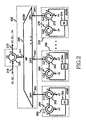
- Fig. 2 is a schematic diagram illustrating the configuration of an ADM according to a first embodiment of the present invention.
- the ADM includes a wavelength division multiplexing/demultiplexing (WDM) unit 220 and n ADM units 250, 260,270 connected to the WDM unit 220.
- WDM wavelength division multiplexing/demultiplexing
- the WDM unit 220 includes an end circulator 230, and a wavelength division multiplexer/demultiplexer 240.
- the end circulator 230 has three ports 2301 to 2303.
- the end circulator 230 is connected at the first and third ports 2301,2303 to an optical fiber 210 for transmission of a multiplexed optical signal.
- the end circulator 230 is also connected at the second port 2302 to a multiplexing port 241 of the WDM 240.
- the end circulator 230 outputs, to the second port 2302, a multiplexed optical signal input to the first port 2301, while outputting, to the third port 2303, an optical signal input to the second port 2302.
- the multiplexing port 241 of the WDM 240 serves as a path for a multiplexed optical signal.
- the WDM 240 has n demultiplexing ports 242 to 244 respectively serving as paths for demultiplexed channels.
- the WDM 240 demultiplexes an optical signal, input to its multiplexing port 241, into channels of different wavelengths and outputs the respective channels to the demultiplexing ports 242 to 244 respectively corresponding to those of the channels.
- the WDM 240 outputs the second channel X2 to its second demultiplexing port 243, while outputting the n-th channel ⁇ n to the n-th demultiplexing port 244.
- the WDM 240 also multiplexes a plurality of channels with different wavelengths respectively input to the n demultiplexing ports 242 to 244, and outputs the resultant multiplexed optical signal to the multiplexing port 241.
- an arrayed waveguide grating may be used which easilyachieves an optical signal channel extension and a simple control while having a high degree of integration.
- the n ADM units 250, 260,270 are connected to the n demultiplexing ports 242 to 244 of the WDM 240, respectively.
- Each of the n ADM units includes a pair of circulators: 252,256 in the case of the ADM unit 250; 262,266 in the case of the ADM unit 260; and 272,276 in the case of the ADM unit 270.
- Each of the ADM units also include a reflector: 254 in the case of the ADM unit 250; 264 in the case of the ADM unit 260; and 274 in the case of the ADM unit 270. Since the n ADM units have the same configuration, a description will be given only in conjunction with the first ADM unit 250.
- the first circulator 252 of the first ADM unit 250 has four ports 2521 to 2524. This first circulator 252 operates to output a channel, input to a higher-order port, to a lower-order port arranged adjacent to the higher-order port.
- the first circulator 252 is connected at the second port 2522 to a corresponding demultiplexing port of the WDM 240, the first demultiplexing port 242.
- the first circulator 252 outputs, to the third port 2523, a first channel ⁇ 1 input to the second port 2522.
- the first circulator 252 outputs, to the fourth port 2524, the first channel ⁇ 1 if reflected back to the third port 2523, thereby dropping the first channel ⁇ 1.
- the reflector 254 of the first ADM unit 250 is connected to the third port 2532 of the first circulator 252 and the second port 2562 of the second circulator 256. In accordance with an ON or OFF state thereof, the reflector 254 reflects or passes a channel inputted thereto.
- a wavelength-independent double-sided reflector may be used which has a transmissivity varying in accordance with a control signal applied thereto.
- the second circulator 256 has three ports 2561 to 2563.
- the second circulator 256 outputs a first channel ⁇ 1, input to the first port 2561, to the second port 2562.
- the second circulator 256 also outputs the first channel ⁇ 1, if reflected back to the second port 2562, to the third port 2563, thereby adding the first channel ⁇ 1.
- operation of the ADM will be described in conjunction with the case of, for example, dropping a first channel ⁇ 1 from an input optical signal, and then adding another first channel ⁇ 1 to the optical signal.
- the reflector 254 of the first ADM unit 250 is put in the ON state by a control unit (not shown), whereas respective reflectors of the second through n-th ADM units 260 to 270 are placed in the OFF state by the control unit.
- respective reflectors of the n ADM units 250 to 270 are referred to as n reflectors.
- the end circulator 230 outputs an optical signal, input to the first port 2301, to the second port 2302 connected to the multiplexing port 241 of the WDM 240.
- the WDM 240 demultiplexes the optical signal input thereto, and then outputs the resultant demultiplexed channels to respective demultiplexing ports 242 to 244 corresponding to the different wavelengths of the channels. That is, the first channel ⁇ 1 of the optical signal is output to the first demultiplexing port 242 connected to the first circulator 252 of the first ADM unit 250.
- the first circulator 252 outputs the first channel ⁇ 1, input to the second port 2522, to the third port 2523 connected to the first reflector 254.
- the first reflector 254 reflects the first channel ⁇ 1 back the third port 2523 of the first circulator 252.
- the first circulator 252 outputs the secondarily-input first channel ⁇ 1 to the fourth port 2524, thereby dropping the first channel ⁇ 1.
- the second circulator 256 outputs a first channel ⁇ 1, input to the first port 2561, to the second port 2562 connected to the first reflector 254.
- the first reflector 254 reflects the first channel ⁇ 1 back to the second port 2562 of the second circulator 256.
- the second circulator 256 outputs the secondarily-input first channel ⁇ 1 to the third port 2524 connected to the first port 2521 of the first circulator 252.
- the first circulator 252 outputs the first channel ⁇ 1, input to its first port 2521, to the second port 2522 connected to a corresponding demultiplexing port of the WDM 240, the first demultiplexing port 242.
- the WDM 240 receives a plurality of channels with different wavelengths from the n ADM units 250 to 270 at the n demultiplexing ports 242 to 244, respectively, multiplexes the received channels and outputs the resultant multiplexed optical signal to the multiplexing port 241.
- the end circulator 230 receives the optical signal from the WDM 240 at the second port 2302, and outputs the received optical signal to the third port 2303.
- Figs. 3a and 3b are schematic diagrams for explaining operations of the n-th ADM unit shown in Fig. 2, respectively.
- Fig. 3a illustrates the operation of the n-th ADM unit 270 for dropping a n-th channel ⁇ n, and then adding another n-th channel ⁇ n.
- the channel dropping operation will be described.
- the n-th reflector 274 is maintained in the ON state.
- the first circulator 272 outputs an n-th channel ⁇ n, input to the second port 2722, to the third port 2723 connected to the n-th reflector 274. Since the n-th reflector 274 is in the ON state, it reflects the n-th channel ⁇ n back to the third port 2723 of the first circulator 272 in the n-th ADM unit 270.
- the first circulator 272 outputs the secondarily-input n-th channel ⁇ n to the fourth port 2724, thereby dropping the n-th channel ⁇ n.
- the second circulator 276 of the n-th ADM unit 276 outputs an n-th channel ⁇ n, input to the first port 2761, to the second port 2762 connected to the n-th reflector 274.
- the n-th reflector 274 reflects the n-th channel ⁇ n back to the second port 2762 of the second circulator 276.
- the second circulator 276 outputs the secondarily-input n-th channel ⁇ n to the third port 2763 connected to the first port 2721 of the first circulator 272.
- the first circulator 272 outputs the n-th channel ⁇ n, input to the first port 2721, to the second port 2722, thereby adding the n-th channel ⁇ n.
- Fig. 3b illustrates the operation of the n-th ADM unit 270 for passing an n-th channel ⁇ n.
- the n-th reflector 274 is maintained in the OFF state.
- the first circulator 272 outputs an n-th channel ⁇ n, input to the second port 2722, to the third port 2723. Since the n-th reflector 274 is in its OFF state, it passes the n-th channel ⁇ n input thereto, so that the n-th channel ⁇ n is input to the second port 2762 of the second circulator 276.
- the second circulator 276 then outputs the n-th channel ⁇ n to the third port 2763 connected to the first port 2721 of the first circulator 272.
- the first circulator 272 outputs the n-th channel ⁇ n, input to the first port 2721, to the second port 2722.
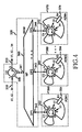
- Fig. 4 is a schematic diagram illustrating the configuration of an ADM according to a second embodiment of the present invention.
- the ADM includes a wavelength division multiplexing/demultiplexing (WDM) unit 320, and n ADM units, 350, 360,370.
- WDM wavelength division multiplexing/demultiplexing
- This ADM has a similar configuration to that of Fig. 2, except for the configurations of the n ADM units 350, 360, 370, so that duplicate description will be omitted.
- the n ADM units 350, 360,370 are connected to the n demultiplexing ports 342 to 344 of the WDM 340, respectively.
- Each of the n ADM units includes a circulator: 352 in the case of the ADM unit 350; 362 in the case of the ADM unit 360; and 372 in the case of the ADM unit 370.
- Each of the n ADM units includes a reflector: 354 in the case of the ADM unit 350; 364 in the case of the ADM unit 360; and 374 in the case of the ADM unit 370. Since the n ADM units have the same configuration, the description will be given only in conjunction with the first ADM unit 350.
- the first circulator 352 of the first ADM unit 350 has seven ports 3521 to 3527.
- the first circulator 352 operates to output a channel, input to a higher-order port thereof, to a lower-order port thereof arranged adjacent to the higher-order port.
- the first circulator 352 is connected at the second port 3522 to a corresponding demultiplexing port of the WDM 340, the first demultiplexing port 342.
- the first circulator 352 outputs, to the third port 3523, a first channel ⁇ 1 input to the second port 3522.
- the first circulator 352 outputs, to the fourth port 3534, the first channel ⁇ 1 if reflected back to the third port 3523, thereby dropping the first channel ⁇ 1.
- the first circulator 352 also outputs, to the sixth port 3526, a first channel ⁇ 1 input to the fifth port 3525.
- the first circulator 352 outputs, to the seventh port 3527, the first channel ⁇ 1 if reflected back to the sixth port 3526.
- the seventh port 3527 of the first circulator 352 is connected to the first port 3521, so that the first circulator 352 outputs the first channel ⁇ 1, input to the first port 3521, to the second port 3522, thereby adding the first channel ⁇ 1.
- the reflector 354 of the first ADM unit 350 is connected to the third and sixth ports 3523,3526 of the first circulator 352. In accordance with an ON or OFF state thereof, the reflector 354 reflects or passes a channel input thereto.
- a wavelength-independent double-sided reflector may be used which has a transmissivity varying in accordance with a control signal applied thereto.Below, operation of the ADM will be described in conjunction with the case of, for example, dropping a first channel ⁇ 1 from an input optical signal, and then adding another first channel ⁇ 1 to the optical signal.
- the reflector 354 of the first ADM unit 350 is placed in the ON state by a control unit (not shown), whereas respective reflectors of the second through n-th ADM units 360 to 370 are placed in the OFF state by the control unit.
- respective reflectors of the n ADM units 350 to 370 are referred to as n reflectors.
- respective circulators of the n ADM units 350 to 370 are referred to as n circulators.
- the end circulator 330 of the WDM unit 320 outputs an optical signal, input to the first port 3301, to the second port 3302 connected to the multiplexing port 341 of the WDM 340.
- the WDM 340 demultiplexes the optical signal input thereto, and then outputs the resultant demultiplexed channels to respective demultiplexing ports 342 to 344 corresponding to the different wavelengths of the channels. That is, the first channel ⁇ 1 of the optical signal is output to the first demultiplexing port 342 connected to the first circulator 352.
- the first circulator 352 outputs the first channel ⁇ 1, input to the second port 3522, to the third port 3523 connected to the first reflector 354.
- the first reflector 354 reflects the first channel ⁇ 1 back to the third port 3523 of the first circulator 352.
- the first circulator 352 outputs the secondarily-input first channel ⁇ 1 to the fourth port 3534, thereby dropping the first channel ⁇ 1.
- the first circulator 352 also outputs a first channel ⁇ 1, input to the fifth port 3525, to the sixth port 3526 connected to the first reflector 354.
- the first reflector 354 reflects the first channel ⁇ 1 back to the sixth port 3526 of the first circulator 352.
- the first circulator 352 outputs the secondarily-input first channel ⁇ 1 to the seventh port 3537 connected to the first port 3521, so that it outputs the first channel ⁇ 1 to the second port 3522 connected to a corresponding demultiplexing port of the WDM 340, the first demultiplexing port 342.
- the WDM 340 receives a plurality of channels with different wavelengths from the n ADM units 350 to 370 at its n demultiplexing ports 342 to 344, multiplexes the received channels, and outputs the resultant multiplexed optical signal to the multiplexing port 341.
- the end circulator 330 receives the optical signal from the WDM 340 at the second port 3302, and outputs the received optical signal to the third port 3303.
- Figs. 5a and 5b are schematic diagrams for explaining operations of the n-th ADM unit shown in Fig. 4, respectively.
- Fig. 5a illustrates the operation of the n-th ADM unit 370 for dropping an n-th channel ⁇ n, and then adding another n-th channel ⁇ n.
- the channel dropping operation will be described.
- the n-th reflector 374 is maintained in the ON state.
- the n-th circulator 372 outputs a n-th channel ⁇ n, input to the second port 3722, to the third port 3723 connected to the n-th reflector 374. Since the n-th reflector 374 is in its ON state, it reflects the n-th channel ⁇ n back to the third port 3723 of the n-th circulator 372.
- the first circulator 372 outputs the secondarily-input n-th channel ⁇ n to the fourth port 3734, thereby dropping the n-th channel ⁇ n.
- the n-th circulator 372 outputs an n-th channel ⁇ n, input to the fifth port 3725, to the sixth port 3726 connected to the n-th reflector 374.
- the n-th reflector 374 reflects the n-th channel ⁇ n back to the sixth port 3726 of the n-th circulator 372.
- the n-th circulator 372 outputs the secondarily-input n-th channel ⁇ n to the seventh port 3727 connected to the first port 3721.
- the n-th circulator 372 outputs the n-th channel ⁇ n, input to the first port 3721, to the second port 3722, thereby adding the n-th channel ⁇ n.
- Fig. 5b illustrates the operation of the n-th ADM unit 370 for passing a n-th channel ⁇ n.
- the n-th reflector 374 is maintained in the OFF state.
- the n-th circulator 372 outputs a n-th channel ⁇ n, input to the second port 3722, to the third port 3723. Since the n-th reflector 374 is in its OFF state, it passes the n-th channel ⁇ n input thereto, so that the n-th channel ⁇ n is input to the sixth port 3726 of the n-th circulator 372.
- the n-th circulator 372 then outputs the n-th channel ⁇ n to the seventh port 3727 connected to its first port 3721.
- the n-th circulator 372 subsequently outputs the n-th channel ⁇ n, input to its first port 3721, to the second port 3722.
- the ADM according to the present invention has advantages in that it operates, irrespective of the wavelength of a channel being added or dropped, while achieving a high-speed operation and an easy control thereof, because it uses circulators, which are passive elements, and wavelength-independent reflectors.
- the ADM according to the present invention can minimize the use of additional elements such as temperature control elements, while having a simple and inexpensive configuration, by virtue of the use of the circulators and wavelength-independent reflectors.
Landscapes
- Physics & Mathematics (AREA)
- Engineering & Computer Science (AREA)
- General Physics & Mathematics (AREA)
- Optics & Photonics (AREA)
- Computer Networks & Wireless Communication (AREA)
- Signal Processing (AREA)
- Microelectronics & Electronic Packaging (AREA)
- Electromagnetism (AREA)
- Optical Communication System (AREA)
- Optical Integrated Circuits (AREA)
Applications Claiming Priority (2)
| Application Number | Priority Date | Filing Date | Title |
|---|---|---|---|
| KR2003039818 | 2003-06-19 | ||
| KR1020030039818A KR100547780B1 (ko) | 2003-06-19 | 2003-06-19 | 순환기와 반사기를 이용한 광 분기/결합기 |
Publications (2)
| Publication Number | Publication Date |
|---|---|
| EP1489768A2 true EP1489768A2 (de) | 2004-12-22 |
| EP1489768A3 EP1489768A3 (de) | 2006-05-17 |
Family
ID=33411765
Family Applications (1)
| Application Number | Title | Priority Date | Filing Date |
|---|---|---|---|
| EP04011559A Withdrawn EP1489768A3 (de) | 2003-06-19 | 2004-05-14 | Optischer Add/Drop-Multiplexer mit Zirkulatoren und Reflektoren |
Country Status (4)
| Country | Link |
|---|---|
| US (1) | US20050008370A1 (de) |
| EP (1) | EP1489768A3 (de) |
| JP (1) | JP3990685B2 (de) |
| KR (1) | KR100547780B1 (de) |
Families Citing this family (2)
| Publication number | Priority date | Publication date | Assignee | Title |
|---|---|---|---|---|
| WO2006006215A1 (ja) * | 2004-07-09 | 2006-01-19 | Fujitsu Limited | 光回路及びそれを用いたリニア系専用のノード装置及びリニア系wdmネットワーク及びツリー系wdmネットワーク |
| GB2549500A (en) * | 2016-04-19 | 2017-10-25 | Airbus Operations Ltd | Node for an optical network |
Family Cites Families (12)
| Publication number | Priority date | Publication date | Assignee | Title |
|---|---|---|---|---|
| US5841918A (en) * | 1996-08-26 | 1998-11-24 | Jds Fitel Inc. | Wavelength and bandwidth tunable optical system |
| JP2977024B2 (ja) * | 1996-12-03 | 1999-11-10 | 日本電気株式会社 | 波長多重通信用光回路及びこれを含む光伝送通信システム |
| GB2321809A (en) * | 1997-01-31 | 1998-08-05 | Stc Submarine Systems Ltd | Add/drop multiplexer |
| US6041152A (en) * | 1997-09-02 | 2000-03-21 | Amphenol Corporation | Multi-channel fiber optic communications system and multiplexer/demultiplexer arrangement therefor |
| KR100237837B1 (ko) * | 1997-10-27 | 2000-01-15 | 이계철 | 파장분할 다중화 전송방식의 다채널 파장분기결합장치 |
| US6240222B1 (en) * | 1998-09-10 | 2001-05-29 | Agere Systems Optoelectronics Guardian Corp. | Wavelength specific operations in optical systems |
| US6154581A (en) * | 1998-10-27 | 2000-11-28 | Adc Telecommunications, Inc. | Multiple port, fiber optic circulator |
| US6243177B1 (en) * | 2000-10-03 | 2001-06-05 | Seneca Networks, Inc. | Bidirectional WDM optical communication system with bidirectional add-drop multiplexing |
| US20020054406A1 (en) * | 2000-11-03 | 2002-05-09 | Gary Duerksen | Bidirectional WDM optical communication network with optical bridge between bidirectional optical waveguides |
| US6950609B2 (en) * | 2001-06-22 | 2005-09-27 | Lucent Technologies Inc. | Tunable, multi-port optical add-drop multiplexer |
| AUPR622101A0 (en) * | 2001-07-06 | 2001-08-02 | University Of Melbourne, The | Optical amplifier and/or add/drop structure |
| US6546167B1 (en) * | 2001-12-11 | 2003-04-08 | Corning Incorporated | Tunable grating optical device |
-
2003
- 2003-06-19 KR KR1020030039818A patent/KR100547780B1/ko not_active Expired - Fee Related
-
2004
- 2004-01-08 US US10/754,029 patent/US20050008370A1/en not_active Abandoned
- 2004-05-14 EP EP04011559A patent/EP1489768A3/de not_active Withdrawn
- 2004-06-18 JP JP2004180388A patent/JP3990685B2/ja not_active Expired - Fee Related
Also Published As
| Publication number | Publication date |
|---|---|
| KR20040110483A (ko) | 2004-12-31 |
| JP2005010785A (ja) | 2005-01-13 |
| KR100547780B1 (ko) | 2006-01-31 |
| JP3990685B2 (ja) | 2007-10-17 |
| EP1489768A3 (de) | 2006-05-17 |
| US20050008370A1 (en) | 2005-01-13 |
Similar Documents
| Publication | Publication Date | Title |
|---|---|---|
| AU4243499A (en) | Add/drop filter for a multi-wavelength lightwave system | |
| EP0649040B1 (de) | Optischer Bandpass-Filter | |
| KR100360769B1 (ko) | 양방향 광분기삽입기 | |
| US20150256283A1 (en) | Optical branching/coupling device and optical branching/coupling method | |
| US6205269B1 (en) | Optical add/drop multiplexer | |
| US6859576B2 (en) | Optical cross-connect system | |
| US7257285B2 (en) | Wavelength-selective switch and integrated wavelength demultiplexer using stacked planar lightwave circuits | |
| US7277639B2 (en) | Bi-directional optical add/drop multiplexer for WDM optical networks | |
| KR100960919B1 (ko) | 평면도파 기술을 이용한 파장선택 스위치 | |
| EP1489768A2 (de) | Optischer Add/Drop-Multiplexer mit Zirkulatoren und Reflektoren | |
| US7298976B2 (en) | Bi-directional optical cross-connect device | |
| US6546167B1 (en) | Tunable grating optical device | |
| US9154254B2 (en) | Wavelength path multiplexing/demultiplexing apparatus and wavelength path multiplexing/demultiplexing method | |
| US20040234266A1 (en) | Reconfigurable add/drop module | |
| US20040218926A1 (en) | Optical add/drop multiplexer | |
| JP4809802B2 (ja) | 光クロスコネクト装置及び光クロスコネクトシステム及び光クロスコネクト装置における信号制御方法 | |
| JP3401189B2 (ja) | 光アド・ドロップ装置 | |
| JP2007155777A (ja) | モニタ回路 | |
| JP2001127705A (ja) | 光分岐多重装置 | |
| JP4366955B2 (ja) | 光機能装置および光機能モジュール | |
| KR20000003063A (ko) | 광 결합 및 분리 장치 | |
| JP4899822B2 (ja) | 光合分波器 | |
| US20030228092A1 (en) | Wavelength-selective optical switch | |
| JP2004045813A (ja) | 光分岐挿入装置 | |
| JP2004289638A (ja) | 波長分割多重処理装置 |
Legal Events
| Date | Code | Title | Description |
|---|---|---|---|
| PUAI | Public reference made under article 153(3) epc to a published international application that has entered the european phase |
Free format text: ORIGINAL CODE: 0009012 |
|
| 17P | Request for examination filed |
Effective date: 20040514 |
|
| AK | Designated contracting states |
Kind code of ref document: A2 Designated state(s): AT BE BG CH CY CZ DE DK EE ES FI FR GB GR HU IE IT LI LU MC NL PL PT RO SE SI SK TR |
|
| AX | Request for extension of the european patent |
Extension state: AL HR LT LV MK |
|
| PUAL | Search report despatched |
Free format text: ORIGINAL CODE: 0009013 |
|
| AK | Designated contracting states |
Kind code of ref document: A3 Designated state(s): AT BE BG CH CY CZ DE DK EE ES FI FR GB GR HU IE IT LI LU MC NL PL PT RO SE SI SK TR |
|
| AX | Request for extension of the european patent |
Extension state: AL HR LT LV MK |
|
| 17Q | First examination report despatched |
Effective date: 20060808 |
|
| AKX | Designation fees paid |
Designated state(s): DE FR GB |
|
| STAA | Information on the status of an ep patent application or granted ep patent |
Free format text: STATUS: THE APPLICATION IS DEEMED TO BE WITHDRAWN |
|
| 18D | Application deemed to be withdrawn |
Effective date: 20081010 |