EP1489807B1 - Générateur de trames d'information pour signaux OFDM avec disposition adaptative des pilotes et des données - Google Patents
Générateur de trames d'information pour signaux OFDM avec disposition adaptative des pilotes et des données Download PDFInfo
- Publication number
- EP1489807B1 EP1489807B1 EP04013606A EP04013606A EP1489807B1 EP 1489807 B1 EP1489807 B1 EP 1489807B1 EP 04013606 A EP04013606 A EP 04013606A EP 04013606 A EP04013606 A EP 04013606A EP 1489807 B1 EP1489807 B1 EP 1489807B1
- Authority
- EP
- European Patent Office
- Prior art keywords
- pilot
- ofdm signal
- value
- received signal
- ofdm
- Prior art date
- Legal status (The legal status is an assumption and is not a legal conclusion. Google has not performed a legal analysis and makes no representation as to the accuracy of the status listed.)
- Expired - Lifetime
Links
Images







Classifications
-
- H—ELECTRICITY
- H04—ELECTRIC COMMUNICATION TECHNIQUE
- H04L—TRANSMISSION OF DIGITAL INFORMATION, e.g. TELEGRAPHIC COMMUNICATION
- H04L5/00—Arrangements affording multiple use of the transmission path
- H04L5/003—Arrangements for allocating sub-channels of the transmission path
- H04L5/0048—Allocation of pilot signals, i.e. of signals known to the receiver
-
- H—ELECTRICITY
- H04—ELECTRIC COMMUNICATION TECHNIQUE
- H04L—TRANSMISSION OF DIGITAL INFORMATION, e.g. TELEGRAPHIC COMMUNICATION
- H04L5/00—Arrangements affording multiple use of the transmission path
- H04L5/003—Arrangements for allocating sub-channels of the transmission path
- H04L5/0044—Allocation of payload; Allocation of data channels, e.g. PDSCH or PUSCH
- H04L5/0046—Determination of the number of bits transmitted on different sub-channels
-
- H—ELECTRICITY
- H04—ELECTRIC COMMUNICATION TECHNIQUE
- H04L—TRANSMISSION OF DIGITAL INFORMATION, e.g. TELEGRAPHIC COMMUNICATION
- H04L5/00—Arrangements affording multiple use of the transmission path
- H04L5/003—Arrangements for allocating sub-channels of the transmission path
- H04L5/0058—Allocation criteria
- H04L5/006—Quality of the received signal, e.g. BER, SNR, water filling
-
- H—ELECTRICITY
- H04—ELECTRIC COMMUNICATION TECHNIQUE
- H04L—TRANSMISSION OF DIGITAL INFORMATION, e.g. TELEGRAPHIC COMMUNICATION
- H04L5/00—Arrangements affording multiple use of the transmission path
- H04L5/0001—Arrangements for dividing the transmission path
- H04L5/0003—Two-dimensional division
- H04L5/0005—Time-frequency
- H04L5/0007—Time-frequency the frequencies being orthogonal, e.g. OFDM(A) or DMT
Definitions
- the present invention relates to generation of transmission signal frame with respect to orthogonal frequency division multiplexing (hereinafter, referred to as "OFDM") transmission system; and more particularly to an OFDM signal frame generator, a transmitter, a signal transmission system and an OFDM signal frame generating method.
- OFDM orthogonal frequency division multiplexing
- the OFDM signal transmission system does not require frequency response equalization of multipath interference, which is caused from multiple propagation path, and then the system is suitable for broadband signal transmission.
- the conditions of propagation path vary depending on the location of a reception terminal. Accordingly, adaptive modulation/demodulation technique, which changes the transmission rate at the transmitting party in accordance with the conditions of the propagation path, is employed.
- a transmitter obtains value of received signal quality from a reception party, and changes the transmission rate in accordance with the value of received signal quality.
- the value of received signal quality is determined at the reception party using a desired value of received signal quality (desired frame error ratio), received signal power value, received signal noise-power ratio and Doppler frequency.
- Fig. 1 shows an example of the conventional OFDM signal frame generator 93, to which the adaptive modulation/demodulation technique is applied.
- a transmission section comprises a frame generator 93, an OFDM modulator 92 and an RF section 91.
- the rate information determiner 94 determines the rate information using the value of received signal quality. Needless to say about the number of information bits, the encoding rate, the modulation order and the spreading factor, the rate information may include information other that the above or only a part of information of the above.
- a data symbol series generator 95 generates a piece of data symbol series in accordance with the rate information. When the reception party requires the rate information for demodulating, the rate information is also included in the information symbol series.
- a pilot symbol generator 96 generates pilot symbols.
- Amultiplexer 97 arranges the generated data symbols and pilot symbols to a time-frequency slot, and generates a transmission signal frame.
- An OFDM modulator 92 OFDM-modulates the signal in the frame. The OFDM modulated signal is subjected to frequency conversion and transmitted by the RF section 91.
- FIG. 2 shows a block diagram of an OFDM transceiver employing the conventional frame generator.
- a data symbol generator 95 in a transmitter 90 comprises an encoder 95A, mapping unit 95B for generating modulation order and a spreading unit 95C.
- a receiver 80 comprises an RF section 81, an OFDM demodulator 82, a channel estimator 83, a received signal quality determiner 8 5 and a despreading/demapping/decoding unit 84.
- the received signal is downconverted by an RF section 81 and subjected to OFDM demodulation by an OFDM demodulator 82.
- the channel estimator 83 carries out channel estimation using the OFDM-demodulated signal and the pilot symbols.
- the channel estimator 83 estimates the channel value (amplitude and phase) of every sub-carrier used for transmission and the value of power of noise applied to a reception antenna.
- the received signal quality determiner 85 calculates the received signal-noise power ratio using the estimated channel value and the estimated noise power value. A value of received signal quality is determined using these values and a desired value of received signal quality.
- the despreading/demapping/decoding unit 84 demodulates the information symbol series using the estimated channel value and the OFDM-demodulated signal.
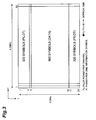
- Fig. 3 shows an example of a generated transmission frame.
- the pilot & data arrangement format has such structure that, for each sub-carrier, 4 pilot symbols are arranged respectively at the head and tail of the frame, and 12 data symbols are arranged in the center of the frame.
- Fig. 13 shows a corresponding table of the value of received signal quality, the rate information (encoding rate, modulation order, spreading factor, number of information bit) and the resulting transmission rate, in the case where the pilot & data arrangement format in Fig. 3 is used.
- the rate determiner determines the above-mentioned rate information using the information in the corresponding table in Fig. 13 corresponding to the value of received signal quality "1-3", which is fed back from the receiver 80.
- Pp/Pi indicates pilot symbol power (Pp) per sub-carrier and power ratio per modulated symbol after despreading.
- the value (Pp/Pi) is preferably about 6-10dB.
- Pp/Pi is about 9dB.
- the transmission signal frame which is generated by the above conventional frame generator, the pilot & data arrangement format and the number of pilot symbols are fixed irrespective of the value of received signal quality.
- the pilot & data arrangement format is fixed.
- the channel estimation accuracy is limited. Accordingly, in an OFDM transmission system, which employs the conventional frame generator, the following inconvenience resides in. That is, in a channel with extremely poor received signal quality (i.e., signal-noise power ratio is extremely low), even when it is attempted to establish a communication with a satisfactorily lowered transmission rate using an adaptive modulation/demodulation technique, the communication fails due to an error in channel estimation.
- Fig. 4 shows an example of a case where, under extremely poor value of received signal quality, the transmission rate is lowered to 4kbps using the conventional frame generator. In this example, with a spreading factor of 240, the transmission rate is lowered.
- Pi gain indicates an increase of Pi in the structure shown in Fig. 4 with respect to Pi in the structure shown in Fig. 3. That is, by spreading to lower the transmission rate, when the reception party carries out despreading, a gain of approximately 24dB per one modulation symbol is obtained. However, in this case, Pp/Pi decreases to "-14dB"; thus, the channel estimation accuracy is degraded.
- An object of the present invention is to provide an OFDM signal frame generator, a transmitter, a signal transmission system and an OFDM signal frame generating method thereby, even in a communication channel of which received signal quality is extremely poor, it is possible to prevent such state that the communication fails.
- an OFDM signal frame generator is an OFDM signal frame generator which comprises rate determining means that, based on a value of received signal quality at a receiver with respect to an OFDM signal received by the receiver, determines the rate information of the OFDM signal, pilot & data arrangement format determining means that, based on the value of received signal quality, determines a pilot & data arrangement format of the OFDM signal, pilot symbol number determining means that, based on the value of received signal quality, determines the number of pilot symbols of the OFDM signal, power amplification rate determining means that, based on the value of received signal quality, determines the power amplification rate of the OFDM signal, data symbol generating means that, based on the rate information and the power amplification rate, generates a piece of data symbol series to be transmitted, and transmission signal frame generating means that, based on generated data symbol, the number of pilot symbols and the pilot & data arrangement format, generates a transmission signal frame of the OFDM signal to be transmitted.
- a transmitter according to the present invention is a transmitter that transmits OFDM signal characterized by including the above OFDM signal frame generator.
- a signal transmission system is a signal transmission system, including a transmitter that transmits OFDM signal and a receiver for receiving the OFDM signal, wherein the receiver comprises received signal quality determining means for determining the value of received signal quality at the receiver with respect to the received OFDM signal, and feedback means for feeding back the determined value of received signal quality to the transmitter; the transmitter comprises: rate determining means that, based on the value of received signal quality obtained by the feedback, determines the rate information of the OFDM signal, pilot & data arrangement format determining means that, based on the value of received signal quality, determines a pilot & data arrangement format of the OFDM signal, pilot symbol number determining means that, based on the value of received signal quality, determines the number of pilot symbols of the OFDM signal, power amplification rate determining means that, based on the value of received signal quality, determines the power amplification rate of the OFDM signal, data symbol generating means that, based on the rate information and the power amplification rate, generates data symbol series to be transmitted
- an OFDM signal frame generating method is an OFDM signal frame generating method of, in a transmitter that transmits OFDM signal to a receiver, generating a transmission signal frame of the OFDM signal, which comprises a rate determining step of, based on a value of received signal quality at a receiver with respect to an OFDM signal received by the receiver, determining the rate information of the OFDM signal, a pilot & data arrangement format determining step of, based on the value of received signal quality, determining a pilot & data arrangement format of the OFDM signal, a pilot symbol number determining step of, based on the value of received signal quality, determining the number of pilot symbols of the OFDM signal, a power amplification rate determining step of, based on the value of received signal quality, determining the power amplification rate of the OFDM signal, a data symbol generating step of, based on the rate information and the power amplification rate, generating data symbol series tobetransmitted, and a transmission signal frame generating step of, based
- the rate information of the OFDM signal, the pilot & data arrangement format of the OFDM signal, the number of pilot symbols of the OFDM signal and the power amplification rate of the OFDM signal are determined, respectively. Further, based on the rate information and the power amplification rate, data symbol series to be transmitted is generated; and based on the data symbol, the number of pilot symbols and the pilot & data arrangement format, the transmission signal frame of the OFDM signal to be transmitted is generated.
- the present invention it is possible to generate the transmission signal frame of the OFDM signal by changing the pilot & data arrangement format, the number of pilot symbols and the power amplification rate in accordance with the value of received signal quality. Owing to this, even in a channel of which received signal quality is poor, the transmission rate is satisfactorily lowered using the adaptive modulation technique, and the number of pilot symbols and the pilot & data arrangement format are changed to maintain the channel estimation accuracy to a satisfactory level. Thus, it is possible to prevent such a state of the communication failure.
- the following methods may be employed. That is, after generating the pilot symbols as many as the number of pilot symbols, the generated pilot symbols and data symbols are synthesized in accordance with the pilot & data arrangement format; or, in the synthesizing process in accordance with the pilot & data arrangement format, the data symbols and the pilot symbols as many as the symbol number are synthesized.
- the receiver feeds back the value of received signal quality to the OFDM signal frame generator.
- the OFDM signal frame generator can change the pilot & data arrangement format and the number of pilot symbols in accordance with an appropriate value of received signal quality, and generate the transmission signal frame of the OFDM signal.
- the pilot & data arrangement format is determined with respect to the used sub-carrier number, the number of pilot symbols in the used sub-carrier and the number of data symbols. In this case, it is possible to generate the transmission signal frame of the OFDM signal based on the generated data symbol, the number of pilot symbols and the pilot & data arrangement format.
- the pilot & data arrangement format as described above, it may be arranged so that the used sub-carrier number is selected at specific intervals on the frequency slot of the transmission signal frame.
- the used sub-carrier number is selected at specific intervals on the frequency slot of the transmission signal frame.
- the used sub-carrier number is changed depending on the frame number. In this case, since different sub-carrier is used in different transmission frame (different time), the frequency diversity gain can be obtained.
- the pilot & data arrangement format it may be preferably arranged so that the frame length is variable depending on the value of received signal quality. In this case, degree of freedom in the generation of the transmission signal frame increases; thus flexible control is available. For example, when the variation of the channel in one frame is extremely small to be assumed as fixed (no variation in the channel), by increasing the frame length, the gain of the power used for the data symbol canbe increased.
- the pilot & data arrangement format determining means may preferably assign the sub-carriers, to which the pilot & data arrangement format is applied based on the value of received signal quality, on the block basis. Tobemore specific, when there is little variation in the channel, there may be such a state that ten frames can be received using the same estimated channel value.
- the first frame is arranged using such format that includes the pilots only and each of the second frame to the tenth frame is arranged using such format that includes data only so that the frame information in several frames can be determined; thus, the amount of transmission data can be increased.
- Fig. 1 is a view showing the configuration of a conventional frame generator.
- Fig. 2 is a block diagram of an OFDM signal transmission system employing the conventional frame generator.
- Fig. 3 is a view showing an example of the configuration of a conventional frame.
- Fig. 4 is a view showing an example of the configuration of a conventional low-speed frame.
- Fig. 5 is a view showing the configuration of a frame generator in accordance with an embodiment of the invention.
- Fig. 6 is a block diagram of an OFDM signal transmission system employing a frame generator according to the embodiment of the invention.
- Fig. 7 is a view showing a first example of a pilot & data arrangement format.
- Fig. 8 is a view showing a second example of the pilot & data arrangement format.
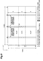
- Fig. 9 is a view showing a third example of the pilot & data arrangement format.
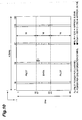
- Fig. 10 is a view showing a fourth-example of the pilot & data arrangement format.
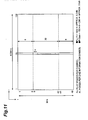
- Fig. 11 is a view showing a fifth example of the pilot & data arrangement format.
- Fig. 12 is a table showing a first example of parameters of OFDM signal.
- Fig. 13 is a table showing an example of relationship between value of received signal quality and rate information, which is used in a conventional rate-determiner.
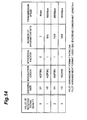
- Fig. 14 is a table showing an example of relationship between value of received signal quality and rate information, which is used in a rate-determiner according to the embodiment.
- Fig. 15 is a table showing an example of relationship between value of received signal quality and pilot & data arrangement format, which is used in a pilot arrangement-determiner according to the embodiment.
- Fig. 16 is a table showing an example of relationship between value of received signal quality and number of pilot symbols, which is used in a pilot symbol number determiner according to the embodiment.
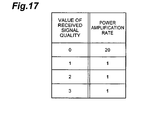
- Fig. 17 is a table showing an example of relationship between value of received signal quality and power amplification rate, which is used in a power-amplification rate determiner according to the embodiment.
- Fig. 18 is a table showing a second example of parameters of OFDM signal.
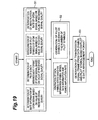
- Fig. 19 is a flowchart showing content of OFDM signal frame-generating processing.
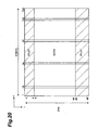
- Fig. 20 is a view showing an example where only a data arrangement format is variable.
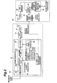
- Fig. 5 shows a block diagram of an OFDM signal frame generator 13 in this embodiment. Differences from the conventional frame generator 93 shown in Fig. 1 are as described below. That is, the frame generator 13 shown in Fig. 5 has a pilot & data arrangement format determiner 20 so as to change the pilot & data arrangement format depending on the value of received signal quality. Also, the frame generator 13 has a pilot symbol number determiner 19 so as to change the number of the pilot symbols depending on the value of received signal quality. Further, the frame generator 13 has a power amplification rate determiner 18 so as to change the power amplification rate depending on the value of received signal quality.
- Fig. 6 is a block diagram showing an OFDM signal transmission system 1 employing the above-mentioned frame generator 13.
- the OFDM signal transmission system 1 is composed of a transmitter 10 provided with the frame generator 13 in Fig. 5 and a receiver 30. Since, the configuration of the receiver 30 is the same as that of the above-described receiver 80 in Fig. 2, the description thereof will be omitted here.
- the OFDM signal transmission system 1 is characterized in the configuration of the frame generator 13 provided to the transmitter 10. Same as the conventional type, the rate information determiner 14 in the frame generator 13 determines a piece of rate information (encoding rate, modulation order, spreading factor) depending on the value of received signal quality. At this time, a corresponding table between the value of received signal quality and the rate information shown in Fig. 14 is used. In this Fig. 14, as the rate information corresponding to the value of received signal quality 0, a piece of low-speed rate information of 4kbps is added.
- the pilot & data arrangement format determiner 20 determines a pilot & data arrangement format using a corresponding table between the value of received signal quality and a pilot & data arrangement format shown in Fig. 15. As demonstrated in Fig. 15, when the quality value of a received signal is 0 (a case of low-rate transmission), a pilot & data arrangement format, which is different from that in the case where the quality value of the received signal is other than 0 (the received signal is any one of 1-3), is used.
- the pilot symbol number determiner 19 determines the number of pilot symbols using a corresponding table between the value of received signal quality and number of pilot symbols shown Fig. 16. When the quality value of the received signal is 0 (a case of low-rate transmission), number of pilot symbols, which is different from that in the case where the value of received signal quality is other than 0 (the value is any one of 1-3), is used.
- the power amplification rate determiner 18 determines the power amplification rate using a corresponding table between value of received signal quality and power amplification rate shown in Fig. 17. This power amplification rate is used when a part of sub-carrier only is used as the pilot & data arrangement format (detailed description will be given later). For example, when only a half of available sub-carriers is used and total transmission power is assigned to the half of the sub-carriers, power amplification rate will be "2". When the power amplification is not carried out, the power amplification rate is fixed to "1".
- rate information of an OFDM signal to be transmitted is determined by the rate information determiner 14; the pilot & data arrangement format is determined by the pilot & data arrangement format determiner 20; the number of pilot symbols is determined by the pilot symbol number determiner 19; and power amplification rate is determined by the power amplification rate determiner 18, respectively.
- the above value of received signal quality is a value fed back to the transmitter 10 from the receiver 30.
- the data symbol series generator 15 carries out a processing on the input information symbol series depending on the rate information and the power amplification rate, which are determined in S1 to generate the data symbol series.
- the pilot symbol generator 16 generates the pilot symbols as many as the determined number of pilot symbols.
- the generated data symbols and pilot symbols are synthesized to generate a transmission signal frame for the OFDM signal.
- the transmission signal frame for the OFDM signal can be generated. Owing to this, even in a channel of which received signal quality is poor, the transmission rate is satisfactorily reduced by using the adaptive modulation technique, and the channel estimation accuracy is also maintained in a satisfactory condition by changing the number of pilot symbols and the pilot & data arrangement format. Thereby, it is possible to prevent such a state of the communication failure.
- pilot & data arrangement format for low-speed transmission corresponding to the value of received signal quality 0
- various examples of the pilot & data arrangement format for low-speed transmission (4kbps) corresponding to the value of received signal quality "0" will be described.
- a guideline for determining the pilot & data arrangement format to carry out low-speed transmission will be given.
- the transmission signal frame as below; i.e., the number of used sub-carriers is reduced to a extent that the frequency diversity effect is obtained to assign the power to the small number of sub-carriers.
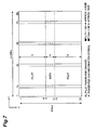
- Fig. 7 shows a first example of the pilot & data arrangement format for low-speed transmission, which is provided by using the above-described guideline.
- the modulation flow of the information symbol series is, for example, as described below.
- 2 bits of the input information symbol series 2 bits of the CRC bit are added resulting in 4 bits.
- the input information symbol series are subjected to the FEC with an encoding rate of "4/7” using a BCH code of rate "4/7" and the "QPSK” of 2bit/Hz, and spread the same with a spreading factor of "4".
- data symbols of 16 chips are generated as the symbols after encoding/modulating/spreading.
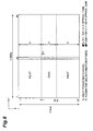
- Fig. 8 shows a second example of the pilot & data arrangement format for low speedprovidedby the present invention.
- the sub-carrier used for transmission is only one; and to the singe sub-carrier, the entire transmission power is assigned (the power amplification rate is "80").
- the modulation flow of the information symbol series in this case is, for example, as described below.
- 2 bits of the input information symbol series 2 bits of the CRC bit are added resulting in 4 bits.
- the information symbol series are subjected to the FEC with an encoding rate of "4/7" using a BCH code of a rate "4/7" and the "QPSK" of 2bit/Hz to spread the same with a spreading factor of "2".
- the Pi gain is increased to approximately 22dB
- the Pp/Pi is also increased to approximately 8dB.
- the frequency diversity at the demodulation is not obtained.
- the receiver has a plurality of reception antennas, the loss of frequency diversity is compensated by the reception diversity gain.
- Fig. 9 shows a third example of the low-speed pilot & data arrangement format, which is provided by the present invention.
- the number of the sub-carrier in Fig. 9, one sub-carrier, which is used for transmission, is changed in accordance with the frame number.
- a pattern which is previously known by the receiver, can be used.
- the modulation flow of the information symbol series is the same as that of the above-described second example.
- Fig. 10 and Fig. 11 show a fourth and fifth examples respectively of the pilot & data arrangement format, which are provided by the present invention.
- the OFDM signal parameters are changed.
- Fig. 18 showing the details, it is understood that the Pi gain canbe increasedupon lengthening the frame length.
- the modulation flow of the information symbol series in the fourth example shown in Fig. 10 is, for example, as described below. To "8 bits" of the input information symbol series, 3 bits of the CRC bit are added resulting in 11 bits.
- the input information symbol series are subjected to the FEC using the BCH code of 4 bits and the "QPSK” of 2bit/Hz, and by spreading the same with a spreading factor of "8", data symbols of 64 chips are generated as the symbols after coding/modulating/spreading.
- the modulation flow of the information symbol series in the fourth example in Fig. 11 is, for example, as described below.
- 3 bits of the CRC bit are added resulting in 11 bits.
- the input information symbol series are subjected to the FEC using the BCH code of 4 bits and the "QPSK" of 2bit/Hz, and spread the same with a spreading factor of "4".
- data symbols of 32 chips are generated as the symbols after coding/modulating/spreading.
- Figs. 7-11 From the first-fifth examples (Figs. 7-11), as possible frame configurations for slow-speed transmission, plural frame configurations are available. Accordingly, one of them is selected and the pilot & data arrangement format in Fig. 15 is determined as "0". Also, in the pilot & data arrangement format "0", it is possible to diversify in the modulation order, the encoding rate and the spreading factor, and plural pieces of rate information other than 4kbps may be included. Further, the number of the pilot & data arrangement formats can be increased.
- the Pi gain can be increased by lengthening the frame length. Accordingly, it is possible to use a pilot & data arrangement format, which has different frame length in Fig. 15. The number of pilot symbols is determined at a point when the pilot & data arrangement format is determined. For example, when the pilot & data arrangement format is determined as "0", as demonstrated in the relationship in Fig. 15 and Fig. 16, the value of received signal quality is "0" and the number of pilot symbols is "48".
- a part of sub-carrier blocks may be assigned (for example, blocks of sub-carrier number 1-5). For example, it may be arranged so that the sub-carriers are previously grouped into several blocks and are assigned on the block basis.
- the first frame is arranged using such format that includes the pilots only and each of the second frame to the tenth frame is arranged using such format that includes data only so that the frame information in several frames can be determined; thus, the amount of transmission data can be increased.
- the present invention it is possible to-change the-pilot & data arrangement format, the number of pilot symbols and the power amplification rate depending on the value of received signal quality to generate the transmission signal frame of the OFDM signal. Owing to this, even in a channel of which received signal quality is poor, the transmission rate can be satisfactorily reduced using the adaptive modulation technique, and by changing the number of pilot symbols and the pilot & data arrangement format, the channel estimation accuracy also can be maintained at a satisfactory level. Thus, it is possible to prevent such a state of the communication failure.
- the embodiments described above show examples based on the frame structure using both head and tail pilot, but the present invention can be easily adapted to the frame structure using only either head or tail pilot, or to the frame structure using scattered pilot.
Landscapes
- Engineering & Computer Science (AREA)
- Signal Processing (AREA)
- Computer Networks & Wireless Communication (AREA)
- Quality & Reliability (AREA)
- Mobile Radio Communication Systems (AREA)
- Detection And Prevention Of Errors In Transmission (AREA)
Claims (7)
- Générateur de trame de signaux OFDM (13), comprenant :des moyens de détermination de vitesse (14) qui, basés sur une valeur de qualité de signaux reçus au niveau d'un récepteur (30) par rapport à un signal OFDM reçu par le récepteur, déterminent les informations de débit du signal OFDM ; caractérisé pardes moyens de détermination de formats de données et de pilotes (20) qui, rapportés à la valeur de la qualité du signal reçu, déterminent un format d'agencement de données et de pilotes du signal OFDM ;des moyens de détermination de nombres de symboles pilotes (19) qui, basés sur ladite valeur de qualité de signal reçu, déterminent le nombre de symboles pilotes du signal OFDM ;des moyens de détermination de débit d'amplification de puissance (18) qui, basés sur ladite valeur de qualité de signal reçu, déterminent le débit d'amplification de puissance du signal OFDM ;des moyens de génération de symboles de données (15) qui, basés sur ladite information de débit et de débit d'amplification de puissance, génèrent une série de symboles de données à transmettre ; etdes moyens de génération de trame de signaux de transmission (17) qui, basés sur la série de symboles de données générés, sur ledit nombre de symboles pilotes et sur ledit format d'agencement de données et pilotes, génèrent une trame de signaux de transmission du signal OFDM à transmettre.
- Générateur de trame de signaux OFDM (13) selon la revendication 1, dans lequel ladite valeur de qualité de signal reçu est réinjectée dans le générateur de trame de signaux OFDM par ledit récepteur (30).
- Générateur de trame de signaux OFDM (13) selon la revendication 1, dans lequel, dans ledit format d'agencement de données et de pilotes, la longueur de trame est variable en fonction de ladite valeur de qualité de signal reçu.
- Générateur de trame de signaux OFDM (13) selon la revendication 1, dans lequel lesdits moyens de détermination de formats d'agencement de données et de pilotes (20) affectent les porteurs secondaires, auxquels est appliqué le format d'agencement de données et de pilotes basé sur ladite valeur de qualité de signal reçu, par bloc.
- Emetteur (10) pour transmettre les signaux OFDM, y compris un générateur de trame de signaux OFDM selon la revendication 1.
- Système de transmission de signaux (1) qui comprend un émetteur (10) pour émettre un signal OFDM et un récepteur (30) pour recevoir le signal OFDM dans le système de transmission de signaux ;
ledit récepteur comprend :des moyens de détermination de qualité de signaux reçus (35) pour déterminer la valeur de la qualité du signal reçu au niveau du récepteur par rapport au signal OFDM reçu ; etdes moyens de rétroaction (35) pour réinjecter la valeur déterminée de la qualité du signal reçu audit émetteur (10) ; etledit émetteur (10) comprend :des moyens de détermination de débit (14) qui, basés sur la valeur de la qualité de signal reçu obtenu par la rétroaction, déterminent les informations de débit du signal OFDM ; l'émetteur étant caractérisé pardes moyens de détermination de formats d'agencement de données et de pilotes (20) qui, basés sur ladite valeur de qualité de signal reçu, déterminent un format d'agencement de données et pilotes du signal OFDM ;des moyens de détermination du nombre symbole de symboles pilotes (19) qui, basés sur ladite valeur de qualité de signaux reçus, déterminent le nombre de symboles pilotes du signal OFDM ;des moyens de détermination de débit d'amplification de puissance (18) qui, basés sur ladite valeur de qualité du signal reçu, déterminent la densité d'amplification de puissance du signal OFDM ;des moyens de génération de symboles de données (15) qui, basés sur ladite information de débit et sur ledit débit d'amplification de puissance, génèrent une série de symboles de données à transmettre ; etdes moyens de génération de trame de signaux de transmission (17) qui, basés sur la série de symboles de données générés, sur ledit nombre de symboles pilotes et sur ledit format d'agencement de données et de pilotes, génèrent une trame de signaux de transmission du signal OFDM à émettre. - Procédé de génération de trame de signaux OFDM, dans un émetteur qui transmet un signal OFDM à un récepteur, pour générer une trame de signal de transmission du signal OFDM, comprenant :une étape de détermination de débit, basée sur une valeur de qualité de signaux reçus au niveau du récepteur, pour la détermination de l'information de débit du signal OFDM ; caractérisé parune étape de détermination de format d'agencement de données et de pilotes, basée sur ladite valeur de qualité des signaux reçus, pour déterminer un format d'agencement de données et de pilotes du signal OFDM ;une étape de détermination du nombre de symboles pilotes, basée sur ladite valeur de qualité du signal reçu, pour déterminer le nombre de symboles pilotes du signal OFDM ;une étape de détermination du débit d'amplification de puissance, basée sur ladite valeur de qualité de signaux reçus, pour déterminer le débit d'amplification de puissance du signal OFDM ;une étape de génération de symboles de données, basée sur ladite information de débit et ledit débit d'amplification de puissance, pour générer la série de symboles de données à transmettre, etune étape de génération de trame de signal de transmission, basée sur la série de symboles de données générés, sur ledit nombre de symboles pilotes et sur ledit format d'agencement de données et de pilotes, pour générer une trame de signal de transmission du signal OFDM à transmettre.
Applications Claiming Priority (2)
| Application Number | Priority Date | Filing Date | Title |
|---|---|---|---|
| JP2003167043 | 2003-06-11 | ||
| JP2003167043 | 2003-06-11 |
Publications (3)
| Publication Number | Publication Date |
|---|---|
| EP1489807A2 EP1489807A2 (fr) | 2004-12-22 |
| EP1489807A3 EP1489807A3 (fr) | 2004-12-29 |
| EP1489807B1 true EP1489807B1 (fr) | 2007-11-14 |
Family
ID=33410885
Family Applications (1)
| Application Number | Title | Priority Date | Filing Date |
|---|---|---|---|
| EP04013606A Expired - Lifetime EP1489807B1 (fr) | 2003-06-11 | 2004-06-09 | Générateur de trames d'information pour signaux OFDM avec disposition adaptative des pilotes et des données |
Country Status (4)
| Country | Link |
|---|---|
| US (1) | US7619963B2 (fr) |
| EP (1) | EP1489807B1 (fr) |
| CN (1) | CN100442793C (fr) |
| DE (1) | DE602004009996T2 (fr) |
Families Citing this family (41)
| Publication number | Priority date | Publication date | Assignee | Title |
|---|---|---|---|---|
| US7796574B2 (en) * | 2002-09-10 | 2010-09-14 | Texas Instruments Incorporated | Multi-carrier reception for ultra-wideband (UWB) systems |
| US8204149B2 (en) | 2003-12-17 | 2012-06-19 | Qualcomm Incorporated | Spatial spreading in a multi-antenna communication system |
| WO2005081439A1 (fr) | 2004-02-13 | 2005-09-01 | Neocific, Inc. | Procedes et dispositif pour des systemes de communication a porteuses multiples comportant une transmission et une retroaction adaptatives |
| US8923785B2 (en) | 2004-05-07 | 2014-12-30 | Qualcomm Incorporated | Continuous beamforming for a MIMO-OFDM system |
| JP4703135B2 (ja) * | 2004-05-25 | 2011-06-15 | 株式会社エヌ・ティ・ティ・ドコモ | 送信機および送信制御方法 |
| WO2006002550A1 (fr) * | 2004-07-07 | 2006-01-12 | Nortel Networks Limited | Systeme et procede de mappage de symboles pour transmission mimo |
| US7978649B2 (en) * | 2004-07-15 | 2011-07-12 | Qualcomm, Incorporated | Unified MIMO transmission and reception |
| KR100724926B1 (ko) | 2004-12-03 | 2007-06-04 | 삼성전자주식회사 | 이동통신 시스템에서 패킷 데이터 심볼 송수신 장치 및방법 |
| JP2006173867A (ja) * | 2004-12-14 | 2006-06-29 | Matsushita Electric Ind Co Ltd | 無線通信装置 |
| KR20060082228A (ko) * | 2005-01-11 | 2006-07-18 | 삼성전자주식회사 | 다중반송파부호분할다중접속 시스템을 위한 파일럿 기반의채널 추정 방법 |
| US7502408B2 (en) * | 2005-04-21 | 2009-03-10 | Broadcom Corporation | RF transceiver having adaptive modulation |
| US20060280113A1 (en) * | 2005-06-10 | 2006-12-14 | Huo David D | Method and apparatus for dynamic allocation of pilot symbols |
| US8009553B2 (en) * | 2005-07-08 | 2011-08-30 | Nec Corporation | Signal generating apparatus and signal generation method |
| WO2007013559A1 (fr) | 2005-07-29 | 2007-02-01 | Matsushita Electric Industrial Co., Ltd. | Dispositif et procédé de communication sans fil |
| DE102005049260A1 (de) * | 2005-10-14 | 2007-04-26 | Siemens Ag | Verfahren und Vorrichtung zur Datenübertragung über eine Übertragungsstrecke |
| JP4841235B2 (ja) * | 2005-11-30 | 2011-12-21 | 富士通株式会社 | 無線基地局、無線通信方法及び無線通信システム |
| KR100978964B1 (ko) | 2006-02-08 | 2010-08-30 | 닛본 덴끼 가부시끼가이샤 | 싱글 캐리어 전송 시스템, 통신 장치 및 그들에 이용하는 싱글 캐리어 전송 방법 |
| JP4899555B2 (ja) * | 2006-03-17 | 2012-03-21 | 富士通株式会社 | 無線通信システム、送信装置及び受信装置 |
| US8543070B2 (en) | 2006-04-24 | 2013-09-24 | Qualcomm Incorporated | Reduced complexity beam-steered MIMO OFDM system |
| US8174995B2 (en) * | 2006-08-21 | 2012-05-08 | Qualcom, Incorporated | Method and apparatus for flexible pilot pattern |
| US8978103B2 (en) * | 2006-08-21 | 2015-03-10 | Qualcomm Incorporated | Method and apparatus for interworking authorization of dual stack operation |
| KR100973118B1 (ko) | 2006-08-21 | 2010-07-29 | 콸콤 인코포레이티드 | 듀얼 스택 동작의 인가를 인터워킹하기 위한 방법 및 장치 |
| KR20080020143A (ko) * | 2006-08-30 | 2008-03-05 | 삼성전자주식회사 | 직교 주파수 분할 다중 시스템에서 데이터 채널을송수신하는 장치 및 방법 |
| JP4957212B2 (ja) * | 2006-11-29 | 2012-06-20 | 富士通株式会社 | 無線フレーム可変制御による最適な無線通信方法及び,これを適用する無線通信システム |
| US20080225689A1 (en) * | 2007-03-13 | 2008-09-18 | Bickerstaff Mark A | Orthogonal frequency division multiplexing having tones with overlaid data and pilot symbols |
| KR20080106133A (ko) * | 2007-05-31 | 2008-12-04 | 엘지전자 주식회사 | 신호 송수신 방법 및 신호 송수신 장치 |
| KR20080106135A (ko) * | 2007-05-31 | 2008-12-04 | 엘지전자 주식회사 | 신호 송수신 방법 및 신호 송수신 장치 |
| WO2009002069A2 (fr) * | 2007-06-22 | 2008-12-31 | Lg Electronics Inc. | Procédé et appareil pour émettre et recevoir un signal |
| US20090003385A1 (en) * | 2007-06-28 | 2009-01-01 | Faraday Technology Corp. | Tx evm improvement of ofdm communication system |
| KR20100025586A (ko) * | 2007-08-02 | 2010-03-09 | 후지쯔 가부시끼가이샤 | 이동 무선 통신 시스템에서의 파일럿 배치 방법 및 이것을 적용하는 송수신 장치 |
| JP5382877B2 (ja) * | 2007-08-31 | 2014-01-08 | パナソニック株式会社 | 通信装置、受信装置、通信方法、受信方法、及び集積回路 |
| KR101664191B1 (ko) * | 2009-08-28 | 2016-10-11 | 삼성전자 주식회사 | 무선 통신 시스템에서 기준 신호 할당 방법 |
| CN101938449A (zh) * | 2010-10-13 | 2011-01-05 | 汪晋宽 | 基于误码率预估的ofdm导频自适应插入方法 |
| EP2911320B1 (fr) * | 2012-10-22 | 2020-12-30 | QUALCOMM Incorporated | Procédé pour configurer une trame sans fil d'équipement utilisateur et équipement utilisateur, et procédé pour configurer une trame sans fil de station de base et station de base |
| JPWO2014068812A1 (ja) * | 2012-10-30 | 2016-09-08 | 日本電気株式会社 | 制御装置、通信システム、通信制御方法、及びプログラム |
| US9191256B2 (en) | 2012-12-03 | 2015-11-17 | Digital PowerRadio, LLC | Systems and methods for advanced iterative decoding and channel estimation of concatenated coding systems |
| US10432370B2 (en) * | 2013-01-14 | 2019-10-01 | Qualcomm Incorporated | Transmission and processing of higher order modulation |
| WO2016082127A1 (fr) * | 2014-11-26 | 2016-06-02 | 华为技术有限公司 | Procédé, appareil et système de transmission d'informations |
| CN109196806B (zh) * | 2016-05-13 | 2021-09-10 | 索尼移动通讯有限公司 | 确定导频与数据的定时关系的系统和方法、可读存储介质 |
| CN108199989B (zh) * | 2018-01-16 | 2020-04-14 | 南方科技大学 | 调度方法及装置、大规模多天线系统和存储介质 |
| DE102022208146B4 (de) * | 2022-08-04 | 2024-06-20 | Continental Automotive Technologies GmbH | Verfahren zum Durchführen einer Fahrzeug-zu-X-Kommunikation und Fahrzeug-zu-X-Kommunikationsmodul |
Family Cites Families (21)
| Publication number | Priority date | Publication date | Assignee | Title |
|---|---|---|---|---|
| KR100221336B1 (ko) * | 1996-12-28 | 1999-09-15 | 전주범 | 직교 주파수 분할 다중화 수신 시스템의 프레임 동기 장치 및 그 방법 |
| JPH11163823A (ja) | 1997-11-26 | 1999-06-18 | Victor Co Of Japan Ltd | 直交周波数分割多重信号伝送方法、送信装置及び受信装置 |
| JPH11178050A (ja) * | 1997-12-10 | 1999-07-02 | Sony Corp | 制御情報伝送方法及び送信装置並びに送受信装置 |
| US6370203B1 (en) * | 1998-11-04 | 2002-04-09 | Ericsson Inc. | Power control for wireless communications system |
| JP2000151548A (ja) * | 1998-11-05 | 2000-05-30 | Matsushita Electric Ind Co Ltd | Ofdm通信装置 |
| JP3686548B2 (ja) * | 1999-05-19 | 2005-08-24 | 松下電器産業株式会社 | 送信装置及びofdmシンボル生成方法 |
| JP4488605B2 (ja) * | 1999-07-30 | 2010-06-23 | パナソニック株式会社 | Ofdm信号の伝送方法、送信装置及び受信装置 |
| JP2001136226A (ja) | 1999-11-05 | 2001-05-18 | Matsushita Electric Ind Co Ltd | 通信装置および通信方法 |
| JP4409743B2 (ja) | 2000-02-25 | 2010-02-03 | パナソニック株式会社 | 無線通信装置及び無線通信方式 |
| JP2001285089A (ja) | 2000-03-31 | 2001-10-12 | Matsushita Electric Ind Co Ltd | 無線通信装置及び送信電力制御方法 |
| EP1720277B1 (fr) * | 2000-07-05 | 2017-09-27 | Sony Deutschland Gmbh | Schéma de symboles pilotes pour plusieurs antennes dans un système OFDM |
| JP3776716B2 (ja) * | 2000-11-17 | 2006-05-17 | 株式会社東芝 | 直交周波数分割多重伝送信号受信装置 |
| US7054375B2 (en) * | 2000-12-22 | 2006-05-30 | Nokia Corporation | Method and apparatus for error reduction in an orthogonal modulation system |
| US7230911B2 (en) * | 2001-05-10 | 2007-06-12 | Intel Corporation | Sparse channel estimation for orthogonal frequency division multiplexed signals |
| JP3628977B2 (ja) | 2001-05-16 | 2005-03-16 | 松下電器産業株式会社 | 無線基地局装置及び通信端末装置 |
| US6751187B2 (en) * | 2001-05-17 | 2004-06-15 | Qualcomm Incorporated | Method and apparatus for processing data for transmission in a multi-channel communication system using selective channel transmission |
| JP2003060609A (ja) | 2001-08-10 | 2003-02-28 | Mitsubishi Electric Corp | 通信方法および通信装置 |
| US7164649B2 (en) * | 2001-11-02 | 2007-01-16 | Qualcomm, Incorporated | Adaptive rate control for OFDM communication system |
| JP2003158499A (ja) | 2001-11-20 | 2003-05-30 | Mitsubishi Electric Corp | 通信方法および通信装置 |
| JP3630134B2 (ja) * | 2001-11-28 | 2005-03-16 | 日本電気株式会社 | チャネル切替方法及びそれを用いた移動通信端末 |
| US7012912B2 (en) * | 2003-05-14 | 2006-03-14 | Qualcomm Incorporated | Power control and scheduling in an OFDM system |
-
2004
- 2004-06-09 EP EP04013606A patent/EP1489807B1/fr not_active Expired - Lifetime
- 2004-06-09 DE DE602004009996T patent/DE602004009996T2/de not_active Expired - Lifetime
- 2004-06-11 CN CNB2004100490685A patent/CN100442793C/zh not_active Expired - Fee Related
- 2004-06-14 US US10/865,817 patent/US7619963B2/en not_active Expired - Fee Related
Also Published As
| Publication number | Publication date |
|---|---|
| CN1574823A (zh) | 2005-02-02 |
| DE602004009996T2 (de) | 2008-09-18 |
| EP1489807A3 (fr) | 2004-12-29 |
| US7619963B2 (en) | 2009-11-17 |
| DE602004009996D1 (de) | 2007-12-27 |
| EP1489807A2 (fr) | 2004-12-22 |
| US20050094552A1 (en) | 2005-05-05 |
| CN100442793C (zh) | 2008-12-10 |
Similar Documents
| Publication | Publication Date | Title |
|---|---|---|
| EP1489807B1 (fr) | Générateur de trames d'information pour signaux OFDM avec disposition adaptative des pilotes et des données | |
| US20220216961A1 (en) | Turbo hsdpa system | |
| US11018821B2 (en) | OFDM frame communication method and apparatus | |
| US7839819B2 (en) | Method and system for adaptive modulations and signal field for closed loop multiple input multiple output (MIMO) wireless local area network (WLAN) system | |
| US8208435B2 (en) | Base station apparatus, user apparatus and method for use in mobile communication system | |
| US8111766B2 (en) | Radio parameter group generating apparatus, transmitter and receiver | |
| EP1689107B1 (fr) | Mécanisme en boucle fermé optionnelle avec des modulations adaptives pour un système MIMO WLAN | |
| US7839823B2 (en) | Apparatus and method for transmitting a control channel message in a mobile communication system | |
| US7660288B2 (en) | Radio communication device | |
| JP4390636B2 (ja) | Ofdm信号フレーム生成器、送信機、信号伝送システム及びofdm信号フレーム生成方法 | |
| US8077669B2 (en) | Method and system for adaptive modulations and signal field for closed loop multiple input multiple output (MIMO) wireless local area network (WLAN) system | |
| US20060120470A1 (en) | System for communicating channel quality information | |
| WO2008026885A1 (fr) | Système et procédé de commande de puissance pour système de communication faisant intervenir un programme de diversification de transmission spatio-temporelle | |
| KR100958636B1 (ko) | 무선통신 시스템에서 변조 및 코드율 레벨에 따른 전용 파일롯의 송수신 제어 방법 및 장치 | |
| US7684765B2 (en) | Transmit antenna switching apparatus and method in MIMO system | |
| KR101430609B1 (ko) | 무선통신시스템에서 채널 추정 장치 및 방법 | |
| JP2010136233A (ja) | マルチキャリア送受信装置およびマルチキャリア送受信方法 | |
| EP1739907B1 (fr) | Méthode, émetteur et récepteur de communication numérique, dans lesquelles la quantité de symboles pilotes est choisie en fonction du type de demodulateur du récepteur |
Legal Events
| Date | Code | Title | Description |
|---|---|---|---|
| PUAI | Public reference made under article 153(3) epc to a published international application that has entered the european phase |
Free format text: ORIGINAL CODE: 0009012 |
|
| PUAL | Search report despatched |
Free format text: ORIGINAL CODE: 0009013 |
|
| 17P | Request for examination filed |
Effective date: 20040609 |
|
| AK | Designated contracting states |
Kind code of ref document: A2 Designated state(s): AT BE BG CH CY CZ DE DK EE ES FI FR GB GR HU IE IT LI LU MC NL PL PT RO SE SI SK TR |
|
| AX | Request for extension of the european patent |
Extension state: AL HR LT LV MK |
|
| AK | Designated contracting states |
Kind code of ref document: A3 Designated state(s): AT BE BG CH CY CZ DE DK EE ES FI FR GB GR HU IE IT LI LU MC NL PL PT RO SE SI SK TR |
|
| AX | Request for extension of the european patent |
Extension state: AL HR LT LV MK |
|
| 17Q | First examination report despatched |
Effective date: 20050622 |
|
| AKX | Designation fees paid |
Designated state(s): DE GB |
|
| 17Q | First examination report despatched |
Effective date: 20050622 |
|
| GRAP | Despatch of communication of intention to grant a patent |
Free format text: ORIGINAL CODE: EPIDOSNIGR1 |
|
| GRAS | Grant fee paid |
Free format text: ORIGINAL CODE: EPIDOSNIGR3 |
|
| GRAA | (expected) grant |
Free format text: ORIGINAL CODE: 0009210 |
|
| AK | Designated contracting states |
Kind code of ref document: B1 Designated state(s): DE GB |
|
| REG | Reference to a national code |
Ref country code: GB Ref legal event code: FG4D |
|
| REF | Corresponds to: |
Ref document number: 602004009996 Country of ref document: DE Date of ref document: 20071227 Kind code of ref document: P |
|
| PLBE | No opposition filed within time limit |
Free format text: ORIGINAL CODE: 0009261 |
|
| STAA | Information on the status of an ep patent application or granted ep patent |
Free format text: STATUS: NO OPPOSITION FILED WITHIN TIME LIMIT |
|
| 26N | No opposition filed |
Effective date: 20080815 |
|
| PGFP | Annual fee paid to national office [announced via postgrant information from national office to epo] |
Ref country code: DE Payment date: 20180530 Year of fee payment: 15 |
|
| PGFP | Annual fee paid to national office [announced via postgrant information from national office to epo] |
Ref country code: GB Payment date: 20180606 Year of fee payment: 15 |
|
| REG | Reference to a national code |
Ref country code: DE Ref legal event code: R119 Ref document number: 602004009996 Country of ref document: DE |
|
| GBPC | Gb: european patent ceased through non-payment of renewal fee |
Effective date: 20190609 |
|
| PG25 | Lapsed in a contracting state [announced via postgrant information from national office to epo] |
Ref country code: DE Free format text: LAPSE BECAUSE OF NON-PAYMENT OF DUE FEES Effective date: 20200101 Ref country code: GB Free format text: LAPSE BECAUSE OF NON-PAYMENT OF DUE FEES Effective date: 20190609 |