EP1489875A1 - Allocation dynamique étendue de ressources pour un transfert de paquets de données - Google Patents
Allocation dynamique étendue de ressources pour un transfert de paquets de données Download PDFInfo
- Publication number
- EP1489875A1 EP1489875A1 EP04014389A EP04014389A EP1489875A1 EP 1489875 A1 EP1489875 A1 EP 1489875A1 EP 04014389 A EP04014389 A EP 04014389A EP 04014389 A EP04014389 A EP 04014389A EP 1489875 A1 EP1489875 A1 EP 1489875A1
- Authority
- EP
- European Patent Office
- Prior art keywords
- usf
- uplink
- slot
- slots
- downlink
- Prior art date
- Legal status (The legal status is an assumption and is not a legal conclusion. Google has not performed a legal analysis and makes no representation as to the accuracy of the status listed.)
- Withdrawn
Links
Images


Classifications
-
- H—ELECTRICITY
- H04—ELECTRIC COMMUNICATION TECHNIQUE
- H04B—TRANSMISSION
- H04B7/00—Radio transmission systems, i.e. using radiation field
- H04B7/24—Radio transmission systems, i.e. using radiation field for communication between two or more posts
- H04B7/26—Radio transmission systems, i.e. using radiation field for communication between two or more posts at least one of which is mobile
- H04B7/2643—Radio transmission systems, i.e. using radiation field for communication between two or more posts at least one of which is mobile using time-division multiple access [TDMA]
- H04B7/2656—Radio transmission systems, i.e. using radiation field for communication between two or more posts at least one of which is mobile using time-division multiple access [TDMA] for structure of frame, burst
-
- H—ELECTRICITY
- H04—ELECTRIC COMMUNICATION TECHNIQUE
- H04W—WIRELESS COMMUNICATION NETWORKS
- H04W72/00—Local resource management
- H04W72/20—Control channels or signalling for resource management
- H04W72/23—Control channels or signalling for resource management in the downlink direction of a wireless link, i.e. towards a terminal
-
- H—ELECTRICITY
- H04—ELECTRIC COMMUNICATION TECHNIQUE
- H04B—TRANSMISSION
- H04B7/00—Radio transmission systems, i.e. using radiation field
- H04B7/24—Radio transmission systems, i.e. using radiation field for communication between two or more posts
- H04B7/26—Radio transmission systems, i.e. using radiation field for communication between two or more posts at least one of which is mobile
- H04B7/2603—Arrangements for wireless physical layer control
-
- H—ELECTRICITY
- H04—ELECTRIC COMMUNICATION TECHNIQUE
- H04W—WIRELESS COMMUNICATION NETWORKS
- H04W24/00—Supervisory, monitoring or testing arrangements
-
- H—ELECTRICITY
- H04—ELECTRIC COMMUNICATION TECHNIQUE
- H04W—WIRELESS COMMUNICATION NETWORKS
- H04W72/00—Local resource management
- H04W72/04—Wireless resource allocation
- H04W72/044—Wireless resource allocation based on the type of the allocated resource
- H04W72/0446—Resources in time domain, e.g. slots or frames
-
- H—ELECTRICITY
- H04—ELECTRIC COMMUNICATION TECHNIQUE
- H04W—WIRELESS COMMUNICATION NETWORKS
- H04W72/00—Local resource management
- H04W72/12—Wireless traffic scheduling
-
- H—ELECTRICITY
- H04—ELECTRIC COMMUNICATION TECHNIQUE
- H04W—WIRELESS COMMUNICATION NETWORKS
- H04W72/00—Local resource management
- H04W72/50—Allocation or scheduling criteria for wireless resources
- H04W72/54—Allocation or scheduling criteria for wireless resources based on quality criteria
- H04W72/542—Allocation or scheduling criteria for wireless resources based on quality criteria using measured or perceived quality
Definitions
- This invention relates to multiple access communication systems and in particular it relates to dynamic resource allocation in time division multiple access systems.
- GSM Multiple access wireless systems
- a number of mobile stations communicate with a network.
- the allocation of physical communication channels for use by the mobile stations is fixed.
- a description of the GSM system may be found in The GSM System for Mobile Communications by M. Mouly and M. B. Pautet, published 1992 with the ISBN reference 2-9507190-0-7.
- TDMA Time Division Multiple Access
- GPRS General Packet Radio Systems
- PDCH Packet Data CHannels
- the time division is by frames of 4.615 ms duration and each frame has eight consecutive 0.577 ms slots.
- the slots may be used for uplink or downlink communication.
- Uplink communication is a transmission from the mobile station for reception by the network to which it is attached. Reception by the mobile station of a transmission from the network is described as downlink.
- access to channels can be allocated in response to changes in channel conditions, traffic loading, Quality of Service and subscription class. Owing to the continually changing channel conditions and traffic loadings a method for dynamic allocation of the available channels is available.
- the amounts of time that the mobile station receives downlink or transmits uplink may be varied and slots allocated accordingly.
- the sequences of slots allocated for reception and transmission at a mobile station, the so-called multislot pattern is usually described in the form RXTY.
- the allocated receive (R) slots being the number X and the allocated transmit slots (T) the number Y.
- a number of multislot classes, one through to 45, is defined for GPRS operation and the maximum uplink (transmission: Tx) and downlink (reception: Rx) slot allocations at a mobile station are specified for each class.
- a GPRS system access to a shared channel is controlled by means of an Uplink Status Flag (USF) transmitted on the downlink in each downlink slot to each communicating mobile station (MS).
- USF Uplink Status Flag
- MS communicating mobile station
- two allocation methods are defined, which differ in the convention about which uplink slots are made available on receipt of a USF in a certain downlink slot.
- the present invention relates to a particular allocation method, in which a number "N" of PDCHs (where a "PDCH” uses a pair of uplink and downlink slots corresponding to each other on a 1-1 basis) are allocated for potential use by the MS.
- the uplink slots available for actual use by a particular mobile station sharing the uplink channel are indicated in the USF.
- the USF is a data item capable of taking 8 values V0- V7, and allows uplink resources to be allocated amongst up to 8 mobiles where each mobile recognises one of these 8 values as "valid", i.e. conferring exclusive use of resources to that mobile.
- a particular mobile station may recognise a different USF value on each of the slots assigned to that mobile station.
- the allocation of uplink slots in the next frame is indicated by the position of the lowest numbered slot that contains a "valid" USF. That is, USF information element takes the value indicating this USF is "valid" for that mobile station. For example, reception of a valid USF in the slot 2 of the present frame will indicate the actual availability for transmission of transmit slots 2...
- N in the next TDMA frame or group of frames, where N is the number of allocated PDCHs.
- N is the number of allocated PDCHs.
- transmission takes place in the next transmit frame at transmit slots n, n+1 et seq. to the allocated number of slots ( N ).
- N the allocated number of slots
- the mobile station is not able instantly to switch from a receive condition to a transmit condition or vice versa and the time allocated to these reconfigurations is known as turnaround time.
- the turnaround time is a concept including both a time required for switching from a receive condition to a transmit condition, that is, a time required for getting ready to transmit, and a time required for switching from a transmit condition to a receive condition, that is, a time required for getting ready to receive. It is also necessary for the mobile station, whilst in packet transfer mode, to perform adjacent cell signal level measurement.
- the mobile station has continuously to monitor all Broadcast Control Channel (BCCH) carriers as indicated by the BA (GPRS) list and the BCCH carrier of the serving cell.
- BCCH Broadcast Control Channel
- a received signal level measurement sample is taken in every TDMA frame, on at least one of the BCCH carriers (3GPP TS 45.008v5 10.0).
- the turnaround and adjacent cell signal level measurement times guaranteed by the network for a mobile station depend on the multislot class to which the mobile claims conformance (3GPP TS 45.002v5.9.0 Annex B).
- the adjacent cell signal level measurements are taken prior to re-configuration from reception to transmission or prior to re-configuration from transmission to reception.
- the combination of adjacent cell signal level measurement and turnaround it is noted that there are four patterns of combinations as described later, including the (two patterns of) combinations of adjacent cell signal level measurement and turnaround (getting ready to transmit or getting ready to receive: hereafter referred to as "transmit/receive preparation” in abbreviated terms) and (another two patterns of) turnaround (transmit/receive preparation) only.
- these combinations are abbreviated as “turnaround (and adjacent cell signal level measurement).”
- a mobile station operating in extended dynamic allocation mode presently must begin uplink transmission in the Tx timeslot corresponding to the Rx timeslot in which the first valid USF is recognised. That is to say that there is a single fixed relationship in the timing of the downlink allocation signalling and subsequent uplink transmission. Owing to the physical limitations of single transceiver mobile stations some desirable multislot configurations are not available for use.
- This may be achieved by altering the fixed relationship in the timing of the downlink allocation signalling and subsequent uplink transmission for certain classes of mobile station.
- there can be a plurality of fixed timing relationships (two in the embodiment below). The timing relationship to be applied depends on the value of the USF and the reception slot in which that USF is received.
- the invention is applied to a GPRS wireless network operating in accordance with the standards applicable to multislot classes.
- uplink transmission (Tx) may be advanced relative to downlink transmission (Rx) due to timing advance (TA), although this is not shown in the illustration.
- TA timing advance
- the amount of time between the first Rx and first Tx of a frame may be reduced a fraction of a slot from the illustrated value of 3 slots due to timing advance.
- FIG 1 two successive TDMA frames are illustrated with downlink (DL) and uplink (UL) slots identified separately.
- the slot positions within the first frame are shown by the numerals 0 through to 7 with the transmission and reception slots offset by a margin of three slots. This is in accordance with the convention that the first transmit frame in a TDMA lags the first receive frame by an offset of 3 (thus ordinary single slot GSM can be regarded as a particular case in which only slot 1 of transmit and receive is used).
- T tb is the time needed for the MS to get ready to transmit
- T ra is the time needed for the MS to perform adjacent cell signal level measurement and get ready to receive.
- T rb is the time needed for the MS to get ready to receive It should be noted that in practice the times T ta and T tb may be reduced by a fraction of a slot due to timing advance. t o is 31 symbol periods timing advance offset
- a pair of a receive frame and a transmit frame corresponds to each other on a 1-1 basis with a predetermined offset, where transmission is started from a transmit slot having the same number as that of a receive slot in which a valid USF was received.
- the starting of transmission is done from the next transmission frame of the transmission frame corresponding to the reception frame in which a valid USF is received.
- the number of transmit slots for transmission in a transmit frame equals to the slot numbers allocated to the transmit frame (N), and slots to be transmitted in a transmit frame are always consecutive. The starting position of transmit slots is maintained until the reception of the next valid USF.
- a steady state R1T4 allocation (downlink 1 slot and uplink 4 slots) for a class 34 mobile station is illustrated.
- one slot is for reception and four slots are for transmission
- a valid USF received on receive slot 0 allows four transmit slots on the next uplink frame.
- the starting position of Tx slots in the next transmission frame is Tx slot 0.
- the number of transmit slots to be transmitted is 4, which is the same as the number of the allocated transmitted slots, and these four transmit slots are consecutive.
- T ra , T rb and T tb each having one slot and T ta having two slots. These periods can be accommodated for this allocation when a valid USF is received in time slot 0.
- the mobile has uplink slots assigned in the usual way, through the use of USF_TN0...USF_TN7 Information Elements in Packet Uplink Assignment and Packet Timeslot Reconfigure messages.
- the network sends the USF, however, for both first and second assigned timeslots on the downlink PDCH associated with the second assigned timeslot.
- the downlink timeslot in which the USF value is contained, and the potentially allocated uplink timeslots (called standard USF and "shifted" USF respectively), and which one should be adopted in the next frame is indicated by the value of the USF.
- a class 34 MS to which one downlink slot and five uplink slots (TN0 - TN4) are assigned is considered.
- the network sends USF_TN0 on timeslot 1 rather than timeslot 0.
- slots marked "B” and "C” provide for T tb and T ra respectively. That is, with this shifted USF, it becomes possible to assign time for transmission preparation T tb (1 slot) and time for adjacent cell signal level measurement and reception preparation T ra (1 slot), which enables 5 slot steady state R1T5 which has been prohibited in the operation illustrated in figure 3.
- FIG 5 Another example of an allocation enabled by implementation of a shifted USF is illustrated in figure 5.
- the application is a class 7 MS with three uplink slots allocated.
- the USF on downlink slot 1 allocating the 3 uplink slots indicates that the first uplink slot available is uplink slot 0 rather than the usual slot 1.
- This provides for the T tb and T ra periods (as required by table 1) and as indicated in figure 5 at D and E respectively. That is, with this shifted USF, it becomes possible to assign time for transmission preparation T tb (1 slot) and time for adjacent cell signal level measurement and reception preparation T ra (3 slot).
- the allocation would not previously have been available in prior art for want of a sufficient period for T ra .
- the 2 slot allocation example illustrated in figure 6 reverts to normal operation i.e. the USF is not shifted. There are no physical constraints in normal allocations for this 2 slot arrangement of figure 6 and the standard USF in time slot 1 allocates uplink slots beginning with uplink slot number 1.
- step 2 in figure 7 may be explicit (i.e. extra signalling) or implicit (automatic for particular multislot class configuration).
- the mobile station receives at step 1 an assignment of uplink resources and USF' s from the network. If at step 2, an indication to use a shifted USF is detected then, for the first USF, the second downlink slot is monitored (step 3) otherwise the first downlink slot is monitored (step 4).
- step 5 when it is judged that a valid USF has been received at step 5 then uplink transmissions are initiated in the first uplink slot from the mobile station (step 6).
- step 6 when it is judged that no valid USF has been received at step 5 then the second downlink slot is monitored for a second USF at step 7 and if the USF is valid (step 8) then uplink transmissions are initiated in the second uplink slot (step 9).
- the allocations are steady state such that the allocations shown are maintained from frame to frame.
- the invention is not restricted to steady state allocations and may be applied also to control of uplink resources that change from one frame to another.
- FIGS. 8 and 9 Examples of state transitions are illustrated in figures 8 and 9. These figures each represent four consecutive frames but have been split for presentation in two top/bottom tiers.
- Figure 8 illustrates the transition from one uplink slot allocation to five uplink slots allocation, for a Class 34 mobile.
- the first (top) two frames show steady state operation with one slot and the next (bottom) two frames show the transitional frames.
- both of the value and the slot location of the USF are changed.
- figure 8 illustrates a state transition from R1T1 to R1T5. Because a valid standard USF_TN4 has been received on downlink slot 4 in the R1T1 state, the starting position of transmit slots in the next transmission frame is uplink slot 4.
- the operation of shifted USF is implemented, and the starting position of transmit slots in the next transmission frame (the R1T5 state after transition) is uplink slot 0.
- the number of transmit slots to be transmitted is 5, which is the same as the number of the allocated transmitted slots, and these five transmit slots are consecutive.
- Figure 9 illustrates the transition from four uplink slots to five uplink slots, for a Class 34 mobile.
- the first two frames show steady state operation with four slots and the next two frames show the transitional frames.
- the USF slot location is constant but the value of the USF is changed.
- figure 9 illustrates a state transition from R1T4 to R1T5. Because a valid standard USF_TN1 has been received on downlink slot 1 in the R1T4 state, the starting position of transmit slots in the next transmission frame is uplink slot 1.
- Table 2 In order to implement the invention in GPRS for example a table (Table 2) may be constructed for a Type 1 MS to allow extended dynamic allocation using the principles below:
- the MS In the case of extended dynamic allocation it is desirable for the MS to be able to "transmit up to its physical slot limit"; specifically, the MS should be able to transmit the maximum number of slots possible according to the limitation of its multislot class, while continuing to receive and decode the USF value on exactly one slot and performing adjacent cell signal level measurements. If it is not possible to define a multislot configuration which permits the MS to "transmit up to its physical slot limit" using T ra , but it would be possible by using T ta , then T ta shall be used.
- T ra will be used as first preference, but if this is not possible T ta will be used as second preference.
- a decision whether or not to use the shifted USF is performed by the base station and a selection of T ra , T tb , T ta , T rb is performed by the mobile station.
- Medium access mode No of Slots T ra shall apply T ta shall apply Applicable Multislot classes Note Uplink, Ext. Dynamic 1-3 Yes - 1-12, 19-45 4 No Yes 33-34, 38-39, 43-45 2 5 Yes - 34, 39 5 5 No Yes 44-45 2,4 6 No Yes 45 5 Down + up, Ext.
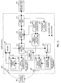
- FIG 10 is a block diagram for a mobile station (MS) which is adaptable to the present embodiment.
- a mobile station (wireless data communication terminal) 100 allows the bi-directional transfer of data between a base station 200 and an external data source and sink 130.
- the base station 200 transmits GPRS signals to the mobile station 100.
- the GPRS signals are received on the receive antenna 102, and are demodulated to baseband ones by a radio frequency demodulator 108.
- the radio frequency demodulator 108 delivers the baseband signals to a baseband data receiver 106.
- the baseband data receiver 106 delivers the received baseband data to a demultiplexer 110.
- the demultiplexer 110 selects either an NCELL measurement unit 112 or a Layer 2 protocol unit 114 to process the above data, depending on its control input from a timing controller 120.
- the downlink baseband data is destined for the NCELL measurement unit 112
- this unit performs adjacent cell signal level measurement, and transmits the resulting information to a Layer 3 protocol unit 116.
- the Layer 3 protocol unit 116 in turn transmits the data to the base station 200 via the uplink.
- Downlink baseband data to be used for adjacent cell signal level measurement is routed to the Layer 3 protocol unit 116.
- the Layer 3 protocol unit 116 separates user plane data and control plane data.
- the user data is sent to a terminal interface unit 118.
- the terminal interface unit 118 sends the data to an external data source and sink 130.
- Control plane data is used to perform internal control functions.
- any GPRS slot allocation frames sent from the base station 200 are used to send parameter data to a slot allocation calculator 128.
- the slot allocation calculator 128 calculates which TDMA slots shall be used for data reception, data transmission, and adjacent cell signal level measurement purposes. This information is sent to a timing controller setting calculator 126.
- the timing controller setting calculator 126 in turn reconfigures a timing controller 120 so as to perform each operation of receive preparation, transmit preparation, and adjacent cell signal level measurement at the correct time.
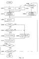
- Figure 11 is a flowchart illustrating an operation example of the slot allocation calculator 128.
- parameter Usf is set at 0.
- the parameter Usf is a parameter indicating the presence/absence of the use of shifted USF, which shows that the shifted USF is not used when it is 0, that is, a standard USF is used, while the shifted USF should be used when it is -1.
- step S1100 parameter Tra_flag is set into 1, while parameters Tr and Tt are set to values of Tra[class] and Ttb[class] respectively.
- Tra_flag is a parameter indicating which one of T ra and T ta should be used as the interval accommodating adjacent cell signal level measurement, where the parameter indicates that T ra should be used when set to 1, and that T ta should be used when set to 0.
- Tra[class] and Ttb[class] are values of T ra and T tb allocated to class (multislot class of a mobile station), which is an input parameter, respectively.
- the number of the class is the attribute of the mobile station.
- the value of T ra , T tb corresponding to each class is prestored in the format of, for example, Table 1.
- parameter Rxmin is set to the value of Tr as set in step S1100.
- Rxmin is a parameter indicating the number of the first slot in downlink receive slots.
- step S1300 the number of transmit slots (Tx) and the number of receive slots (Rx) is compared with each other. As the result of the comparison, if Tx ⁇ Rx (S1300: NO), the process goes to step S1400, whereas if Tx ⁇ Rx (S1300: YES), it moves on to step S1600. It is noted that each value of Tx, Rx is included in the radio resource control plane data from the upper layer.
- step S1400 it is further judged whether Rx + Tt is less than 3 + Usf or not.
- "3" is the number of slots for downlink and uplink offset.
- parameter Txmin is set to Tr + 3 + Usf.
- parameter Txmin is set to Tr + Rx + Tt.
- Txmin is a parameter indicating the number of the first slot in uplink transmit slots. Incidentally, the value set in step S1100 is used for Tr and Tt.
- step S1700 parameter Txmax is set to Txmin + Tx.
- Txmax is a parameter indicating the number of the next slot of the last slot in uplink transmit slots.
- the value set in step S1500 or step S1600 is used for Txmin.
- step S1800 it is judged whether to end processing or not. Specifically, regarding an identical Usf value, it is judged whether the processing from step S1100 through step S1700 is the first execution or the second execution. As the result of the judgment, if the processing is not ended, that is, if the processing from step S1100 through step S1700 is the first execution (S1800: NO), the process goes to step S1900, whereas if the processing from step S1100 through step S1700 is the second execution (S1800: YES), a string of processing is ended.
- step S1900 it is judged whether Txmax set in step S1700 is less than 8 or not.
- "8" is the number of slots contained in one frame.
- step 2000 it is judged whether parameter Tra_flag is set into 0 or not, that is, whether T ta is used in place of T ra as an interval including adjacent cell signal level measurement. As the result of the judgment, if Tra_flag is put into 0 (S2000: YES), the process goes to step S2100, whereas if Tra_flag is not put into 0 (S2000: NO), it moves on to step S2200.
- step S2100 parameter Tra_flag is set into 0, while parameters Tr and Tt are set to values of Trb[class] and Tta[class] respectively, and after that, the process goes to step S1200 to repeat processing from step S1200 through step S1700.
- Trb[class] and Tta[class] are values of T rb and T ta allocated to class, which is an input parameter, respectively.
- the number of class is included in the radio resource control plane data from the upper layer, and in addition, the value of T rb , T ta corresponding to each class is prestored in the format of Table 1. Incidentally, in this case, upon completion of the processing from step S1200 through step S1700 (S1800: YES), the string of processing is ended.
- step S2200 parameter Usf is set into -1, and the process goes to step S1100 to repeat processing from step S1100 through step S1700.
- step S1100 to repeat processing from step S1100 through step S1700.
- each value of parameters at the time of the end, Usf, Tra_flag, Rxmin, Txmin, and Txmax, is outputted as information.
- Txmax is set to Txmin + Tx (S1700). Then, if Txmax is equal to or less than 8 (S1900: YES), T ta is used as a period accommodating adjacent cell signal level measurement, that is, T rb and T ta is used as a combination of intervals.
- step S1200 through step S1700 assumes the processing in step S1200 through step S1700 to be reexecuted once again after step S2100 for each Usf value
- the invention is not limited to such a case. If any parameters other than Usf and Tra_flag (for example, Rxmin, Txmin, Txmax, etc.) are unnecessary as output, that is, if it is just enough to set Usf and Tra_flag only, the processing may be ended immediately without repeating any processing from step S1200 through step S1700 after step S2100.
- Usf and Tra_flag for example, Rxmin, Txmin, Txmax, etc.
- the timing controller 120 is responsible for determining and controlling the timing of the transmission and reception of signals toward the base station 200, and the reception of measurement data. In accordance with the calculation result of the slot allocation calculator 128, the timing controller 120 controls the precise timing and behavior of the radio frequency modulator 122, radio frequency demodulator 108, baseband data receiver 106, baseband transmitter 124, and demultiplexer 110.
- User data transmitted from an external data source and sink 130 is accepted by a terminal interface unit 118, and given to a Layer 3 protocol unit 116.
- the Layer 3 protocol unit 116 multiplexes the data with any protocol control data, and transmits it via a Layer 2 protocol unit 114.
- the Layer 2 protocol unit 114 in turn transmits the multiplexed data to a baseband transmitter 124. Subsequently, the multiplexed data is modulated by a radio frequency modulator 122, and then is transmitted over a transmit antenna 104.
- Figure 12 is a block diagram for a base station which is adaptable to the present embodiment.
- a wireless base station 200 allows the bi-directional transfer of data between a plurality of mobile stations 100 and an external base station controller (BSC: Base Station Controller) 230.
- BSC Base Station Controller
- Each mobile station 100 transmits precisely-timed GPRS signals to the base station 200.
- the GPRS signals are received on the receive antenna 202, and are demodulated to baseband ones by a radio frequency demodulator 208.
- the radio frequency demodulator 208 delivers the baseband signals to a baseband data receiver 206. If multiple receive frequencies are used, there is one set of radio frequency demodulator 208 and baseband data receiver 206 per frequency.
- the baseband data receiver 206 delivers the received baseband data to a multiplexer MS 210.
- the multiplexer MS 210 marks which MS the data has arrived from depending on its control input from a timing controller 220, and forwards all data to a Layer 2 protocol unit 214.
- the Layer 2 protocol unit 214 maintains a separate context for each mobile station 100.
- Downlink baseband data to be used for adjacent cell signal level measurement is routed to the Layer 3 protocol unit 216.
- the Layer 3 protocol unit 216 maintains a separate context for each mobile station 100.
- the Layer 3 protocol unit 216 separates user plane data and radio resource control plane data.
- User data and radio resource control plane data is sent to a BSC interface unit 218.
- the BSC interface unit 218 sends the data to an external Base Station Controller 230.
- Radio resource control plane data is used to perform internal control functions.
- a slot allocation calculator 228 calculates, typically according to the data rate required, which GPRS slots are allocated for each mobile station 100. This information is sent to the Layer 3 protocol unit 216. The Layer 3 protocol unit 216 sends allocation information to the mobile station 100. This information is also sent to a timing controller setting calculator 226.
- other MS slot allocator 232 receives necessary data from the external Base Station Controller 230 via the BSC interface unit 218, and calculates allocation information for other mobile stations. This information is also sent to the timing controller setting calculator 226. The timing controller setting calculator 226 in turn reconfigures a timing controller 220 so as to perform each of receive and transmit actions towards each mobile station 100 at the correct time.
- Figure 13 is a flowchart illustrating an operation example of the slot allocation calculator 228. It is noted that, because parameters Usf, Tra_flag, Tr, Tt, Rxmin, Txmin, and Txmax are the same as parameters illustrated in figure 11, explanation thereof is omitted.
- step S3000 parameter Usf is set at 0.
- step S3100 parameter Tra_flag is set into 1, while parameters Tr and Tt are set to values of Tra[class] and Ttb[class] respectively.
- Tra[class] and Ttb[class] are values of T ra and T tb allocated to class (multislot class of a mobile station), which is an input parameter, respectively.
- the number of the class is the attribute of the mobile station.
- the value of T ra , T tb corresponding to each class is prestored in the format of, for example, Table 1.
- parameter Rxmin is set to the value of Tr as set in step S3100.
- step S3300 the number of transmit slots (Tx) and the number of receive slots (Rx) is compared with each other. As the result of the comparison, if Tx ⁇ Rx (S3300: NO), the process goes to step S3400, whereas if Tx ⁇ Rx (S3300: YES), it moves on to step S3600. It is noted that each value of Tx, Rx is included in the radio resource control plane data from the upper layer.
- step S3400 it is further judged whether Rx + Tt is less than 3 + Usf or not.
- "3" is the number of slots for downlink and uplink offset.
- parameter Txmin is set to Tr + 3 + Usf.
- parameter Txmin is set to Tr + Rx + Tt.
- the value set in step S3100 is used for Tr and Tt.
- step S3700 parameter Txmax is set to Txmin + Tx.
- the value set in step S3500 or step S3600 is used for Txmin.
- step S3800 it is judged whether to end processing or not. Specifically, regarding an identical Usf value, it is judged whether the processing from step S3100 through step S3700 is the first execution or the second execution. As the result of the judgment, if the processing is not ended, that is, if the processing from step S3100 through step S3700 is the first execution (S3800: NO), the process goes to step S3900, whereas if the processing from step S3100 through step S3700 is the second execution (S3800: YES), a string of processing is ended.
- step S3900 it is judged whether Txmax set in step S3700 is less than 8 or not.
- "8" is the number of slots contained in one frame.
- step 4000 it is judged whether parameter Tra_flag is set into 0 or not, that is, whether T ta is used in place of T ra as an interval including adjacent cell signal level measurement. As the result of the judgment, if Tra_flag is put into 0 (S4000: YES), the process goes to step S4100, whereas if Tra_flag is not put into 0 (S4000: NO), it moves on to step S4200.
- step S4100 parameter Tra_flag is set into 0, while parameters Tr and Tt are set to values of Trb[class] and Tta[class] respectively, and after that, the process goes to step S4200 to repeat processing from step S4200 through step S4700.
- Trb[class] and Tta[class] are values of T rb and T ta allocated to class, which is an input parameter, respectively.
- the number of class is included in the radio resource control plane data from the upper layer, and in addition, the value of T rb , T ta corresponding to each class is prestored in the format of Table 1. Incidentally, in this case, upon completion of the processing from step S3200 through step S3700 (S3800: YES), the string of processing is ended.
- step S4200 parameter Usf is set into -1, and the process goes to step S3100 to repeat processing from step S3100 through step S3700.
- step S3100 to repeat processing from step S3100 through step S3700.
- each value of parameters at the time of the end, Usf, Tra_flag, Rxmin, Txmin, and Txmax, is outputted as information.
- Txmin is set to Tr + Rx + Tt (S3600), and otherwise, Txmin is set to Tr + 3 (S3500).
- Txmax is set to Txmin + Tx (S3700). Then, if Txmax is equal to or less than 8 (S3900: YES), T ra is used as a period accommodating adjacent cell signal level measurement, that is, T ra and T tb is used as a combination of intervals.
- Txmin is set to Tr + Rx + Tt (S3600), and otherwise, Txmin is set to Tr + 3 (S3500).
- Txmax is set to Txmin + Tx (S3700).
- T ta is used as a period accommodating adjacent cell signal level measurement, that is, T rb and T ta is used as a combination of intervals.
- T ra may be used or not by the MS as a period accommodating adjacent cell signal level measurement by performing processing from step S3100 through step S4100, and T ta is used when T ra can not be used. That is, in a case where the shifted USF is used, T ra will be used as first preference, but if this is not possible T ta will be used as second preference.
- step S3200 through step S3700 assumes the processing in step S3200 through step S3700 to be reexecuted once again after step S4100 for each Usf value
- the invention is not limited to such a case. If any parameters other than Usf and Tra_flag (for example, Rxmin, Txmin, Txmax, etc.) are unnecessary as output, that is, if it is just enough to set Usf and Tra_flag only, the processing may be ended immediately without repeating any processing from step S3200 through step S3700 after step S4100.
- Usf and Tra_flag for example, Rxmin, Txmin, Txmax, etc.
- the timing controller 220 is responsible for determining and controlling the timing of the transmission and reception of signals toward the mobile station 100. In accordance with the calculation result of the slot allocation calculator 228, the timing controller 220 controls the precise timing and behavior of the radio frequency modulator 222, radio frequency demodulator 208, baseband data receiver 206, baseband transmitter 224, multiplexer MS 210, and demultiplexer MS 234.
- a Base Station Controller 230 User data and control data transmitted from a Base Station Controller 230 is accepted by a BSC interface unit 218, and given to a Layer 3 protocol unit 216.
- the Layer 3 protocol unit 216 multiplexes the data with any radio resource control data, and transmits it via a Layer 2 protocol unit 214.
- the Layer 2 protocol unit 214 in turn transmits the multiplexed data to a demultiplexer MS 234.
- the demultiplexer MS 234 provides the data for each mobile station 100 on the correct TDMA slot to the correct baseband transmitter 224. Subsequently, the data is modulated by a radio frequency modulator 222, and then is transmitted over a transmit antenna 204. If multiple transmit frequencies are used, there is one set of radio frequency modulator 222 and baseband data transmitter 224 per frequency.
Landscapes
- Engineering & Computer Science (AREA)
- Computer Networks & Wireless Communication (AREA)
- Signal Processing (AREA)
- Mobile Radio Communication Systems (AREA)
- Time-Division Multiplex Systems (AREA)
- Data Exchanges In Wide-Area Networks (AREA)
- Radio Relay Systems (AREA)
Applications Claiming Priority (2)
| Application Number | Priority Date | Filing Date | Title |
|---|---|---|---|
| GB0314093 | 2003-06-18 | ||
| GB0314093A GB2398708B (en) | 2003-06-18 | 2003-06-18 | Extended dynamic resource allocation in packet data transfer |
Publications (1)
| Publication Number | Publication Date |
|---|---|
| EP1489875A1 true EP1489875A1 (fr) | 2004-12-22 |
Family
ID=27636762
Family Applications (6)
| Application Number | Title | Priority Date | Filing Date |
|---|---|---|---|
| EP04000183A Expired - Lifetime EP1489871B1 (fr) | 2003-06-18 | 2004-01-07 | Allocation dynamique étendue de ressources pour un transfert de paquets de données |
| EP05009523A Expired - Lifetime EP1562395B1 (fr) | 2003-06-18 | 2004-01-07 | Allocation dynamique étendue de ressources pour un transfert de paquets de données |
| EP04000182A Withdrawn EP1489870A1 (fr) | 2003-06-18 | 2004-01-07 | Allocation dynamique étendue de ressources pour un transfert de paquets de données |
| EP04000184A Expired - Lifetime EP1489872B1 (fr) | 2003-06-18 | 2004-01-07 | Allocation dynamique étendue de ressources pour un transfert de paquets de données |
| EP04000181A Expired - Lifetime EP1489869B1 (fr) | 2003-06-18 | 2004-01-07 | Allocation dynamique étendue de ressources pour un transfert de paquets de données |
| EP04014389A Withdrawn EP1489875A1 (fr) | 2003-06-18 | 2004-06-18 | Allocation dynamique étendue de ressources pour un transfert de paquets de données |
Family Applications Before (5)
| Application Number | Title | Priority Date | Filing Date |
|---|---|---|---|
| EP04000183A Expired - Lifetime EP1489871B1 (fr) | 2003-06-18 | 2004-01-07 | Allocation dynamique étendue de ressources pour un transfert de paquets de données |
| EP05009523A Expired - Lifetime EP1562395B1 (fr) | 2003-06-18 | 2004-01-07 | Allocation dynamique étendue de ressources pour un transfert de paquets de données |
| EP04000182A Withdrawn EP1489870A1 (fr) | 2003-06-18 | 2004-01-07 | Allocation dynamique étendue de ressources pour un transfert de paquets de données |
| EP04000184A Expired - Lifetime EP1489872B1 (fr) | 2003-06-18 | 2004-01-07 | Allocation dynamique étendue de ressources pour un transfert de paquets de données |
| EP04000181A Expired - Lifetime EP1489869B1 (fr) | 2003-06-18 | 2004-01-07 | Allocation dynamique étendue de ressources pour un transfert de paquets de données |
Country Status (11)
| Country | Link |
|---|---|
| US (5) | US6952413B2 (fr) |
| EP (6) | EP1489871B1 (fr) |
| JP (5) | JP3586463B1 (fr) |
| KR (4) | KR100733220B1 (fr) |
| CN (5) | CN1806459B (fr) |
| AT (3) | ATE316747T1 (fr) |
| BR (4) | BRPI0411527A (fr) |
| DE (4) | DE602004000280T2 (fr) |
| ES (4) | ES2296001T3 (fr) |
| GB (4) | GB2398708B (fr) |
| WO (5) | WO2004114708A1 (fr) |
Cited By (6)
| Publication number | Priority date | Publication date | Assignee | Title |
|---|---|---|---|---|
| WO2006111014A1 (fr) * | 2005-04-18 | 2006-10-26 | Sierra Wireless, Inc. | Classe a intervalles de temps multiples configurable pour dispositifs sans fil |
| EP1734775A1 (fr) * | 2005-06-15 | 2006-12-20 | Matsushita Electric Industrial Co., Ltd. | Allocation dynamique dos à dos |
| EP2028772A1 (fr) * | 2007-07-31 | 2009-02-25 | Research In Motion Limited | Techniques de communication de paquets de données à utiliser pour augmenter le débit de données sur les dispositifs de communication mobiles |
| WO2009096846A1 (fr) | 2008-01-30 | 2009-08-06 | Telefonaktiebolaget L M Ericsson (Publ) | Créneaux temporels de mesure de configuration pour terminaux mobiles dans un système tdd |
| CN101047426B (zh) * | 2006-04-18 | 2010-08-04 | 华为技术有限公司 | 一种上行分组数据信道的分配方法及数据的发送方法 |
| US7957418B2 (en) | 2007-07-31 | 2011-06-07 | Research In Motion Limited | Data burst communication techniques for use in increasing data throughput to mobile communication devices |
Families Citing this family (34)
| Publication number | Priority date | Publication date | Assignee | Title |
|---|---|---|---|---|
| GB2398708B (en) * | 2003-06-18 | 2005-01-05 | Matsushita Electric Industrial Co Ltd | Extended dynamic resource allocation in packet data transfer |
| GB2416961B (en) * | 2004-08-04 | 2007-03-14 | Matsushita Electric Industrial Co Ltd | Improved uplink status flag detection method for GPRS |
| GB2419498B (en) * | 2004-10-25 | 2009-07-01 | Matsushita Electric Industrial Co Ltd | Method of allocating timeslots in a packet-switched circuit in a mobile communication system, mobile station, base station and computer program |
| EP1807943B1 (fr) * | 2004-10-25 | 2010-12-08 | Telefonaktiebolaget LM Ericsson (publ) | Gestion de ressources en canaux fonction de la qualite radio |
| US7639653B2 (en) * | 2005-03-10 | 2009-12-29 | Qualcomm Incorporated | Method and apparatus for managing uplink resource allocation in a communication system |
| JP4755254B2 (ja) * | 2005-11-01 | 2011-08-24 | テレフオンアクチーボラゲット エル エム エリクソン(パブル) | 無線通信システムにおける方法および装置 |
| CN100450215C (zh) * | 2006-04-06 | 2009-01-07 | 华为技术有限公司 | 指示终端发送数据所采用的分组数据信道的方法 |
| EP1848135B1 (fr) * | 2006-04-19 | 2012-02-22 | Motorola Mobility, Inc. | Procédé de transfert multi-créneau de données par paquets |
| US8238322B2 (en) | 2006-06-30 | 2012-08-07 | Nokia Corporation | Optimizing of channel allocation in a wireless communications system |
| CN1917706B (zh) * | 2006-08-18 | 2011-01-19 | 华为技术有限公司 | 上行信道资源配置的方法及相应终端和基站及其系统 |
| WO2008041417A1 (fr) * | 2006-09-29 | 2008-04-10 | Mitsubishi Electric Corporation | procédé de notification d'attribution de canal, procédé de communication et appareil de communication |
| EP2109973B1 (fr) * | 2007-01-09 | 2013-01-02 | Nokia Corporation | Appareil, procédé et produit-programme informatique permettant le partage dynamique de ressources entre des attributions dans les sens montant et descendant pour des utilisateurs codés séparément |
| GB2446446B (en) * | 2007-02-06 | 2012-01-25 | Toshiba Res Europ Ltd | Wireless communications apparatus |
| GB0702325D0 (en) * | 2007-02-07 | 2007-03-21 | Siemens Ag | Uplink allocation strategies |
| KR20080092222A (ko) | 2007-04-11 | 2008-10-15 | 엘지전자 주식회사 | Tdd 시스템에서의 데이터 전송 방법 |
| CN100579078C (zh) * | 2007-06-19 | 2010-01-06 | 华为技术有限公司 | 实现上行资源调度的方法、基站和用户终端 |
| CN101355788B (zh) * | 2007-07-25 | 2011-12-07 | 华为技术有限公司 | 发送上行资源调度请求的方法和装置 |
| GB0715281D0 (en) * | 2007-08-07 | 2007-09-12 | Nokia Siemens Networks Oy | Reduced transmission time interval |
| GB2452697A (en) | 2007-08-14 | 2009-03-18 | Nec Corp | Dynamically allocating new resources to a node provided with persistently allocated resources |
| TWI466478B (zh) * | 2007-09-14 | 2014-12-21 | Koninkl Philips Electronics Nv | 致能非同步無線裝置間的通信之裝置及方法 |
| US8705506B2 (en) | 2007-11-16 | 2014-04-22 | Qualcomm Incorporated | Time reservation for a dominant interference scenario in a wireless communication network |
| JP5157510B2 (ja) * | 2008-02-19 | 2013-03-06 | 富士通株式会社 | 無線通信制御方法および無線端末 |
| US8081984B2 (en) * | 2008-04-30 | 2011-12-20 | Telefonaktiebolaget L M Ericsson (Publ) | UL/DL scheduling for full bandwidth utilization |
| US9078270B2 (en) * | 2008-07-03 | 2015-07-07 | Qualcomm Incorporated | Opportunistic relay scheduling in wireless communications |
| CN101635957B (zh) * | 2008-07-22 | 2012-12-19 | 电信科学技术研究院 | 实现drx状态下多用户资源分配均衡的方法和装置 |
| KR101578253B1 (ko) * | 2008-08-12 | 2015-12-16 | 텔레호낙티에볼라게트 엘엠 에릭슨(피유비엘) | 무선 통신 시스템에서의 니어 컴패니언 모드 |
| KR101352171B1 (ko) * | 2009-04-21 | 2014-01-15 | 블랙베리 리미티드 | 데이터 전송 동안 타임슬롯의 모니터링을 조정하기 위한 시스템 및 방법 |
| US8537765B2 (en) * | 2010-02-17 | 2013-09-17 | Telefonaktiebolaget Lm Ericsson (Publ) | Methods and nodes in a wireless communication system |
| BR112012021509B1 (pt) * | 2010-02-26 | 2021-09-08 | Blackberry Limited | Método para uma estação móvel se comunicar com uma rede de comunicações sem fio, mídia legível por computador e estação móvel |
| US9538434B2 (en) * | 2010-04-06 | 2017-01-03 | Telefonaktiebolaget Lm Ericsson (Publ) | Method and arrangement in a wireless communication system |
| CN103178925A (zh) * | 2011-12-21 | 2013-06-26 | 华为技术有限公司 | 上行数据的发送控制方法、终端及网络侧设备 |
| US9628171B2 (en) * | 2013-03-15 | 2017-04-18 | Blackberry Limited | Systems and methods for timeslot assignment in a wireless network |
| JP6171443B2 (ja) * | 2013-03-21 | 2017-08-02 | 富士通株式会社 | データ転送制御方法、中継装置、及びデータ転送制御装置 |
| KR102823585B1 (ko) | 2016-12-07 | 2025-06-20 | 삼성디스플레이 주식회사 | 유기 발광 표시 장치 및 그 제조 방법 |
Citations (4)
| Publication number | Priority date | Publication date | Assignee | Title |
|---|---|---|---|---|
| US5822308A (en) * | 1995-07-17 | 1998-10-13 | National Semiconductor Corporation | Multi-tasking sequencer for a TDMA burst mode controller |
| US20010030956A1 (en) * | 2000-01-07 | 2001-10-18 | Gopal Chillariga | Dynamic channel allocation in multiple-access communication systems |
| US20020128035A1 (en) * | 2000-10-30 | 2002-09-12 | Nokia Corporation | Method and apparatus for transmitting and receiving dynamic configuration parameters in a third generation cellular telephone network |
| US6477151B1 (en) * | 1997-11-11 | 2002-11-05 | Nokia Mobile Phones Ltd. | Packet radio telephone services |
Family Cites Families (40)
| Publication number | Priority date | Publication date | Assignee | Title |
|---|---|---|---|---|
| US156546A (en) * | 1874-11-03 | Improvement in bale-ties | ||
| US15839A (en) * | 1856-10-07 | Bumper arrangement for uncoupling railroad-cars | ||
| US128035A (en) * | 1872-06-18 | Improvement in draught-regulators for hot-air furnaces | ||
| US30956A (en) * | 1860-12-18 | Operating the valves of steam-engines | ||
| JPS59218789A (ja) * | 1983-05-06 | 1984-12-10 | 信越化学工業株式会社 | フレキシブルプリント配線基板およびその製造方法 |
| JPS6072344A (ja) * | 1983-09-28 | 1985-04-24 | Nippon Telegr & Teleph Corp <Ntt> | 二線式デイジタル双方向中継器 |
| DE69331142T2 (de) * | 1993-09-17 | 2002-07-04 | Alcatel Sa | Kommunikationsprotokoll für ein mobiles kommunikationssystem |
| US5420851A (en) * | 1993-11-24 | 1995-05-30 | At&T Corp. | Method of multiple access |
| US5594720A (en) * | 1993-11-24 | 1997-01-14 | Lucent Technologies Inc. | Multiple access cellular communication with dynamic slot allocation and reduced co-channel interferences |
| FI114178B (fi) * | 1995-01-09 | 2004-08-31 | Nokia Corp | Radiokapasiteetin dynaaminen jakaminen TDMA-järjestelmässä |
| FI101114B (fi) * | 1995-04-25 | 1998-04-15 | Nokia Telecommunications Oy | Epäsymmetrinen suurinopeuksinen datasiirtomenetelmä matkapuhelinverkos sa |
| JPH09172674A (ja) * | 1995-12-20 | 1997-06-30 | Matsushita Electric Ind Co Ltd | 無線通信システム |
| JPH10126847A (ja) * | 1996-10-15 | 1998-05-15 | Hitachi Ltd | Phsシステムにおけるスロット割当数の動的制御方式及びphsシステム |
| US6031832A (en) * | 1996-11-27 | 2000-02-29 | Telefonaktiebolaget L M Ericsson (Publ) | Method and apparatus for improving performance of a packet communications system |
| AU6177298A (en) * | 1997-02-21 | 1998-09-09 | Motorola, Inc. | Method and apparatus for allocating spectral resources in a wireless communication system |
| FI104877B (fi) * | 1997-03-27 | 2000-04-14 | Nokia Networks Oy | Resurssinvarausmekanismi pakettiradioverkossa |
| FR2764463B1 (fr) * | 1997-06-10 | 1999-09-24 | Alsthom Cge Alcatel | Procede d'allocation de canaux de transmission a une station mobile, notamment en mode semi-duplex, dans un reseau de telecommunications mobiles, en mode paquet |
| CN1253050C (zh) * | 1997-09-25 | 2006-04-19 | 西门子公司 | 复时隙移动站最佳化的相邻信道搜索和时隙分配 |
| GB2332595B (en) * | 1997-12-17 | 2002-12-04 | Motorola Ltd | Slot allocation in a TDD wireless communications system |
| US6501745B1 (en) * | 1998-02-13 | 2002-12-31 | Telefonaktiebolaget Lm Ericsson (Publ) | Method for variable block scheduling indication by an uplink state flag in a packet data communication system |
| EP1005243A1 (fr) * | 1998-11-24 | 2000-05-31 | TELEFONAKTIEBOLAGET LM ERICSSON (publ) | Procédé d'accès pour système de télécommunications mobile |
| US20020098860A1 (en) | 1999-01-12 | 2002-07-25 | Pecen Mark E. | Transmit power control method and apparatus |
| FI106498B (fi) * | 1999-03-16 | 2001-02-15 | Nokia Mobile Phones Ltd | Menetelmä siirtoikkunan valinnassa ja matkaviestin |
| GB2356528A (en) * | 1999-11-17 | 2001-05-23 | Ericsson Telefon Ab L M | Channel allocation in telecommunication networks |
| US6778509B1 (en) * | 1999-11-19 | 2004-08-17 | Hughes Electronics Corporation | MAC layer protocol for a satellite based packet switched services |
| EP1107620B1 (fr) * | 1999-12-10 | 2004-04-14 | Lucent Technologies Inc. | Système d'interrogations multiples pour GPRS |
| EP1139614A1 (fr) | 2000-03-28 | 2001-10-04 | Lucent Technologies Inc. | Méthode améliorée de décodage des Uplink Status Flags pour des utilisateurs RT-EGPRS |
| EP1164809A1 (fr) * | 2000-05-31 | 2001-12-19 | Lucent Technologies Inc. | Procédé d'attribution de canal pour faciliter le contrôle de la puissance de transmission et de l'antenne adaptative |
| JP2002016570A (ja) * | 2000-06-30 | 2002-01-18 | Denso Corp | 基地局および通信システム |
| US6747962B2 (en) * | 2000-10-10 | 2004-06-08 | Nokia Corporation | Method and apparatus for sharing uplink state flag (USF) with multiple uplink temporary block flows (TBFs) |
| US20020156839A1 (en) * | 2000-10-26 | 2002-10-24 | Scott Peterson | System for providing localized content information via wireless personal communication devices |
| FI20002810A7 (fi) * | 2000-12-20 | 2002-06-21 | Nokia Corp | Viestintäjärjestelmä datalohkojen ja lupien lähettämiseksi |
| FI112138B (fi) * | 2001-02-09 | 2003-10-31 | Nokia Corp | Kehittynyt menetelmä ja järjestely tiedon siirtämiseksi pakettiradiopalvelussa |
| ITMI20010721A1 (it) * | 2001-04-04 | 2002-10-04 | Siemens Inf & Comm Networks | Metodo per offrire servizi a pacchetto su risorse radio condivise da piu' utenti in un sistema di tipo tdd-cdma |
| NZ511155A (en) * | 2001-04-18 | 2002-12-20 | Tait Electronics Ltd | A system for allocation of a control channel at a base station in a trunked network using a plurality of repeaters which provide respective radio channels |
| EP1261227A1 (fr) | 2001-05-21 | 2002-11-27 | Motorola, Inc. | Méthode et appareil pour augmenter le transfert de données dans un système de télécommunication |
| GB2375925B (en) * | 2001-05-25 | 2004-12-01 | Motorola Inc | Allocation of timeslolts in a cellular communication system |
| JP3540298B2 (ja) * | 2001-09-05 | 2004-07-07 | 三菱電機株式会社 | 移動無線機の制御方法および移動無線機 |
| US6987753B2 (en) | 2001-10-09 | 2006-01-17 | Alcatel Canada Inc | Apparatus and method for dynamic bandwidth allocation with minimum bandwidth guarantee |
| GB2398708B (en) * | 2003-06-18 | 2005-01-05 | Matsushita Electric Industrial Co Ltd | Extended dynamic resource allocation in packet data transfer |
-
2003
- 2003-06-18 GB GB0314093A patent/GB2398708B/en not_active Expired - Fee Related
- 2003-06-18 GB GB0415062A patent/GB2403101B/en not_active Expired - Fee Related
- 2003-06-18 GB GB0414899A patent/GB2400279B/en not_active Expired - Fee Related
- 2003-06-18 GB GB0415063A patent/GB2403102B/en not_active Expired - Fee Related
-
2004
- 2004-01-07 AT AT04000181T patent/ATE316747T1/de not_active IP Right Cessation
- 2004-01-07 ES ES05009523T patent/ES2296001T3/es not_active Expired - Lifetime
- 2004-01-07 EP EP04000183A patent/EP1489871B1/fr not_active Expired - Lifetime
- 2004-01-07 AT AT04000184T patent/ATE314797T1/de not_active IP Right Cessation
- 2004-01-07 ES ES04000181T patent/ES2257711T3/es not_active Expired - Lifetime
- 2004-01-07 AT AT04000183T patent/ATE314796T1/de not_active IP Right Cessation
- 2004-01-07 ES ES04000184T patent/ES2254990T3/es not_active Expired - Lifetime
- 2004-01-07 EP EP05009523A patent/EP1562395B1/fr not_active Expired - Lifetime
- 2004-01-07 DE DE602004000280T patent/DE602004000280T2/de not_active Expired - Lifetime
- 2004-01-07 ES ES04000183T patent/ES2255690T3/es not_active Expired - Lifetime
- 2004-01-07 DE DE602004000282T patent/DE602004000282T2/de not_active Expired - Lifetime
- 2004-01-07 DE DE602004000340T patent/DE602004000340T2/de not_active Expired - Lifetime
- 2004-01-07 EP EP04000182A patent/EP1489870A1/fr not_active Withdrawn
- 2004-01-07 EP EP04000184A patent/EP1489872B1/fr not_active Expired - Lifetime
- 2004-01-07 DE DE602004009657T patent/DE602004009657T2/de not_active Expired - Lifetime
- 2004-01-07 EP EP04000181A patent/EP1489869B1/fr not_active Expired - Lifetime
- 2004-02-26 BR BRPI0411527-9A patent/BRPI0411527A/pt not_active Application Discontinuation
- 2004-02-26 KR KR1020057024257A patent/KR100733220B1/ko not_active Expired - Fee Related
- 2004-02-26 KR KR1020057024258A patent/KR100742446B1/ko not_active Expired - Fee Related
- 2004-02-26 WO PCT/JP2004/002303 patent/WO2004114708A1/fr not_active Ceased
- 2004-02-26 BR BRPI0411587-2A patent/BRPI0411587A/pt not_active Application Discontinuation
- 2004-02-26 KR KR1020057024268A patent/KR20060018895A/ko not_active Withdrawn
- 2004-02-26 CN CN2004800166571A patent/CN1806459B/zh not_active Expired - Fee Related
- 2004-02-26 CN CNA2004800168026A patent/CN1806461A/zh not_active Withdrawn
- 2004-02-26 BR BRPI0411474-4A patent/BRPI0411474A/pt not_active Application Discontinuation
- 2004-02-26 WO PCT/JP2004/002306 patent/WO2004114711A1/fr not_active Ceased
- 2004-02-26 WO PCT/JP2004/002304 patent/WO2004114709A1/fr not_active Ceased
- 2004-02-26 CN CNA2004800166779A patent/CN1806460A/zh active Pending
- 2004-02-26 BR BRPI0411562-7A patent/BRPI0411562A/pt not_active Application Discontinuation
- 2004-02-26 CN CNA2004800168045A patent/CN1806462A/zh not_active Withdrawn
- 2004-02-26 KR KR1020057024267A patent/KR100781478B1/ko not_active Expired - Fee Related
- 2004-02-26 WO PCT/JP2004/002305 patent/WO2004114710A1/fr not_active Ceased
- 2004-02-27 US US10/787,538 patent/US6952413B2/en not_active Expired - Fee Related
- 2004-02-27 US US10/787,537 patent/US7058041B2/en not_active Expired - Fee Related
- 2004-02-27 US US10/787,243 patent/US7046656B2/en not_active Expired - Fee Related
- 2004-02-27 US US10/787,536 patent/US20040258037A1/en not_active Abandoned
- 2004-03-03 JP JP2004059870A patent/JP3586463B1/ja not_active Expired - Fee Related
- 2004-03-03 JP JP2004059867A patent/JP2005012755A/ja active Pending
- 2004-03-03 JP JP2004059868A patent/JP3586461B1/ja not_active Expired - Fee Related
- 2004-03-03 JP JP2004059869A patent/JP3586462B1/ja not_active Expired - Fee Related
- 2004-06-16 CN CNA200480016805XA patent/CN1806463A/zh active Pending
- 2004-06-16 WO PCT/JP2004/008776 patent/WO2004114713A1/fr not_active Ceased
- 2004-06-17 US US10/869,102 patent/US20040258029A1/en not_active Abandoned
- 2004-06-17 JP JP2004180201A patent/JP2005012810A/ja active Pending
- 2004-06-18 EP EP04014389A patent/EP1489875A1/fr not_active Withdrawn
Patent Citations (4)
| Publication number | Priority date | Publication date | Assignee | Title |
|---|---|---|---|---|
| US5822308A (en) * | 1995-07-17 | 1998-10-13 | National Semiconductor Corporation | Multi-tasking sequencer for a TDMA burst mode controller |
| US6477151B1 (en) * | 1997-11-11 | 2002-11-05 | Nokia Mobile Phones Ltd. | Packet radio telephone services |
| US20010030956A1 (en) * | 2000-01-07 | 2001-10-18 | Gopal Chillariga | Dynamic channel allocation in multiple-access communication systems |
| US20020128035A1 (en) * | 2000-10-30 | 2002-09-12 | Nokia Corporation | Method and apparatus for transmitting and receiving dynamic configuration parameters in a third generation cellular telephone network |
Cited By (11)
| Publication number | Priority date | Publication date | Assignee | Title |
|---|---|---|---|---|
| WO2006111014A1 (fr) * | 2005-04-18 | 2006-10-26 | Sierra Wireless, Inc. | Classe a intervalles de temps multiples configurable pour dispositifs sans fil |
| US7397781B2 (en) | 2005-04-18 | 2008-07-08 | Sierra Wireless, Inc. | Configurable multislot class for wireless devices |
| US7620023B2 (en) | 2005-04-18 | 2009-11-17 | Sierra Wireless, Inc. | Configurable multislot class for wireless devices |
| CN101176378B (zh) * | 2005-04-18 | 2011-02-23 | 施克莱无线公司 | 用于无线装置的可配置的多时隙等级 |
| EP1734775A1 (fr) * | 2005-06-15 | 2006-12-20 | Matsushita Electric Industrial Co., Ltd. | Allocation dynamique dos à dos |
| WO2006133811A1 (fr) * | 2005-06-15 | 2006-12-21 | Matsushita Electric Industrial Co., Ltd. | Affectation dynamique successive de ressources |
| CN101047426B (zh) * | 2006-04-18 | 2010-08-04 | 华为技术有限公司 | 一种上行分组数据信道的分配方法及数据的发送方法 |
| EP2028772A1 (fr) * | 2007-07-31 | 2009-02-25 | Research In Motion Limited | Techniques de communication de paquets de données à utiliser pour augmenter le débit de données sur les dispositifs de communication mobiles |
| US7957418B2 (en) | 2007-07-31 | 2011-06-07 | Research In Motion Limited | Data burst communication techniques for use in increasing data throughput to mobile communication devices |
| WO2009096846A1 (fr) | 2008-01-30 | 2009-08-06 | Telefonaktiebolaget L M Ericsson (Publ) | Créneaux temporels de mesure de configuration pour terminaux mobiles dans un système tdd |
| US8441951B2 (en) | 2008-01-30 | 2013-05-14 | Telefonatiebolaget Lm Ericsson (Publ) | Configuration measurement time slots for mobile terminals in a TDD system |
Also Published As
Similar Documents
| Publication | Publication Date | Title |
|---|---|---|
| EP1489871B1 (fr) | Allocation dynamique étendue de ressources pour un transfert de paquets de données | |
| EP1471757A2 (fr) | Attribution dynamique des ressources dans le transfert de données par paquets |
Legal Events
| Date | Code | Title | Description |
|---|---|---|---|
| PUAI | Public reference made under article 153(3) epc to a published international application that has entered the european phase |
Free format text: ORIGINAL CODE: 0009012 |
|
| AK | Designated contracting states |
Kind code of ref document: A1 Designated state(s): AT BE BG CH CY CZ DE DK EE ES FI FR GB GR HU IE IT LI LU MC NL PL PT RO SE SI SK TR |
|
| AX | Request for extension of the european patent |
Extension state: AL HR LT LV MK |
|
| 17P | Request for examination filed |
Effective date: 20050221 |
|
| 17Q | First examination report despatched |
Effective date: 20050415 |
|
| AKX | Designation fees paid |
Designated state(s): AT BE BG CH CY CZ DE DK EE ES FI FR GB GR HU IE IT LI LU MC NL PL PT RO SE SI SK TR |
|
| 17Q | First examination report despatched |
Effective date: 20050415 |
|
| RAP1 | Party data changed (applicant data changed or rights of an application transferred) |
Owner name: PANASONIC CORPORATION |
|
| 18D | Application deemed to be withdrawn |
Effective date: 20080626 |
|
| STAA | Information on the status of an ep patent application or granted ep patent |
Free format text: STATUS: THE APPLICATION IS DEEMED TO BE WITHDRAWN |
|
| R18D | Application deemed to be withdrawn (corrected) |
Effective date: 20080708 |