EP1490281B1 - Regulation du cadencement d'envois postaux en cours de traitement par un systeme postal - Google Patents
Regulation du cadencement d'envois postaux en cours de traitement par un systeme postal Download PDFInfo
- Publication number
- EP1490281B1 EP1490281B1 EP03716684A EP03716684A EP1490281B1 EP 1490281 B1 EP1490281 B1 EP 1490281B1 EP 03716684 A EP03716684 A EP 03716684A EP 03716684 A EP03716684 A EP 03716684A EP 1490281 B1 EP1490281 B1 EP 1490281B1
- Authority
- EP
- European Patent Office
- Prior art keywords
- velocity
- dwell
- article
- gap time
- time
- Prior art date
- Legal status (The legal status is an assumption and is not a legal conclusion. Google has not performed a legal analysis and makes no representation as to the accuracy of the status listed.)
- Expired - Lifetime
Links
- 238000000034 method Methods 0.000 claims abstract description 22
- 230000003247 decreasing effect Effects 0.000 claims description 4
- 230000007423 decrease Effects 0.000 abstract description 5
- 230000032258 transport Effects 0.000 description 30
- 239000012530 fluid Substances 0.000 description 17
- 238000012937 correction Methods 0.000 description 14
- 238000012545 processing Methods 0.000 description 11
- 230000003044 adaptive effect Effects 0.000 description 10
- 238000007789 sealing Methods 0.000 description 9
- 230000001133 acceleration Effects 0.000 description 8
- 238000007639 printing Methods 0.000 description 8
- 230000008569 process Effects 0.000 description 8
- 230000001276 controlling effect Effects 0.000 description 7
- 239000003292 glue Substances 0.000 description 6
- 230000007704 transition Effects 0.000 description 6
- 230000001419 dependent effect Effects 0.000 description 5
- 238000010586 diagram Methods 0.000 description 5
- 238000004364 calculation method Methods 0.000 description 4
- 238000005259 measurement Methods 0.000 description 4
- 238000013459 approach Methods 0.000 description 3
- 238000013461 design Methods 0.000 description 3
- 230000004044 response Effects 0.000 description 3
- 238000009736 wetting Methods 0.000 description 3
- 238000003708 edge detection Methods 0.000 description 2
- -1 for example Chemical compound 0.000 description 2
- 238000012423 maintenance Methods 0.000 description 2
- 238000012986 modification Methods 0.000 description 2
- 230000004048 modification Effects 0.000 description 2
- 239000013641 positive control Substances 0.000 description 2
- 230000001105 regulatory effect Effects 0.000 description 2
- XLYOFNOQVPJJNP-UHFFFAOYSA-N water Substances O XLYOFNOQVPJJNP-UHFFFAOYSA-N 0.000 description 2
- 238000005303 weighing Methods 0.000 description 2
- BXESZVNFNSBGGR-UHFFFAOYSA-N 3-(2,3-dimethoxyphenyl)-1-(9-methyl-2-phenyl-9H-imidazo[1,2-a]benzimidazol-3-yl)prop-2-en-1-one Chemical compound COC1=CC=CC(C=CC(=O)C=2N3C4=CC=CC=C4N(C)C3=NC=2C=2C=CC=CC=2)=C1OC BXESZVNFNSBGGR-UHFFFAOYSA-N 0.000 description 1
- 238000007792 addition Methods 0.000 description 1
- 230000001174 ascending effect Effects 0.000 description 1
- 230000000712 assembly Effects 0.000 description 1
- 238000000429 assembly Methods 0.000 description 1
- 230000009286 beneficial effect Effects 0.000 description 1
- 230000003115 biocidal effect Effects 0.000 description 1
- 239000003139 biocide Substances 0.000 description 1
- 230000033228 biological regulation Effects 0.000 description 1
- 238000004891 communication Methods 0.000 description 1
- 238000013481 data capture Methods 0.000 description 1
- 238000012217 deletion Methods 0.000 description 1
- 230000037430 deletion Effects 0.000 description 1
- 239000006260 foam Substances 0.000 description 1
- 239000006261 foam material Substances 0.000 description 1
- 238000007641 inkjet printing Methods 0.000 description 1
- 238000012886 linear function Methods 0.000 description 1
- 238000004519 manufacturing process Methods 0.000 description 1
- 239000000463 material Substances 0.000 description 1
- 230000007246 mechanism Effects 0.000 description 1
- 230000003287 optical effect Effects 0.000 description 1
- 230000002093 peripheral effect Effects 0.000 description 1
- 238000002360 preparation method Methods 0.000 description 1
- 230000008439 repair process Effects 0.000 description 1
- 238000006467 substitution reaction Methods 0.000 description 1
- 238000012546 transfer Methods 0.000 description 1
- 230000007723 transport mechanism Effects 0.000 description 1
Images


Classifications
-
- B—PERFORMING OPERATIONS; TRANSPORTING
- B65—CONVEYING; PACKING; STORING; HANDLING THIN OR FILAMENTARY MATERIAL
- B65H—HANDLING THIN OR FILAMENTARY MATERIAL, e.g. SHEETS, WEBS, CABLES
- B65H43/00—Use of control, checking, or safety devices, e.g. automatic devices comprising an element for sensing a variable
-
- B—PERFORMING OPERATIONS; TRANSPORTING
- B65—CONVEYING; PACKING; STORING; HANDLING THIN OR FILAMENTARY MATERIAL
- B65H—HANDLING THIN OR FILAMENTARY MATERIAL, e.g. SHEETS, WEBS, CABLES
- B65H29/00—Delivering or advancing articles from machines; Advancing articles to or into piles
- B65H29/12—Delivering or advancing articles from machines; Advancing articles to or into piles by means of the nip between two, or between two sets of, moving tapes or bands or rollers
- B65H29/125—Delivering or advancing articles from machines; Advancing articles to or into piles by means of the nip between two, or between two sets of, moving tapes or bands or rollers between two sets of rollers
-
- B—PERFORMING OPERATIONS; TRANSPORTING
- B65—CONVEYING; PACKING; STORING; HANDLING THIN OR FILAMENTARY MATERIAL
- B65H—HANDLING THIN OR FILAMENTARY MATERIAL, e.g. SHEETS, WEBS, CABLES
- B65H2301/00—Handling processes for sheets or webs
- B65H2301/40—Type of handling process
- B65H2301/44—Moving, forwarding, guiding material
- B65H2301/445—Moving, forwarding, guiding material stream of articles separated from each other
- B65H2301/4452—Regulating space between separated articles
-
- B—PERFORMING OPERATIONS; TRANSPORTING
- B65—CONVEYING; PACKING; STORING; HANDLING THIN OR FILAMENTARY MATERIAL
- B65H—HANDLING THIN OR FILAMENTARY MATERIAL, e.g. SHEETS, WEBS, CABLES
- B65H2511/00—Dimensions; Position; Numbers; Identification; Occurrences
- B65H2511/10—Size; Dimensions
- B65H2511/11—Length
-
- B—PERFORMING OPERATIONS; TRANSPORTING
- B65—CONVEYING; PACKING; STORING; HANDLING THIN OR FILAMENTARY MATERIAL
- B65H—HANDLING THIN OR FILAMENTARY MATERIAL, e.g. SHEETS, WEBS, CABLES
- B65H2511/00—Dimensions; Position; Numbers; Identification; Occurrences
- B65H2511/20—Location in space
- B65H2511/22—Distance
-
- B—PERFORMING OPERATIONS; TRANSPORTING
- B65—CONVEYING; PACKING; STORING; HANDLING THIN OR FILAMENTARY MATERIAL
- B65H—HANDLING THIN OR FILAMENTARY MATERIAL, e.g. SHEETS, WEBS, CABLES
- B65H2513/00—Dynamic entities; Timing aspects
- B65H2513/10—Speed
-
- B—PERFORMING OPERATIONS; TRANSPORTING
- B65—CONVEYING; PACKING; STORING; HANDLING THIN OR FILAMENTARY MATERIAL
- B65H—HANDLING THIN OR FILAMENTARY MATERIAL, e.g. SHEETS, WEBS, CABLES
- B65H2513/00—Dynamic entities; Timing aspects
- B65H2513/20—Acceleration or deceleration
-
- B—PERFORMING OPERATIONS; TRANSPORTING
- B65—CONVEYING; PACKING; STORING; HANDLING THIN OR FILAMENTARY MATERIAL
- B65H—HANDLING THIN OR FILAMENTARY MATERIAL, e.g. SHEETS, WEBS, CABLES
- B65H2513/00—Dynamic entities; Timing aspects
- B65H2513/50—Timing
- B65H2513/52—Age; Duration; Life time or chronology of event
-
- B—PERFORMING OPERATIONS; TRANSPORTING
- B65—CONVEYING; PACKING; STORING; HANDLING THIN OR FILAMENTARY MATERIAL
- B65H—HANDLING THIN OR FILAMENTARY MATERIAL, e.g. SHEETS, WEBS, CABLES
- B65H2557/00—Means for control not provided for in groups B65H2551/00 - B65H2555/00
- B65H2557/20—Calculating means; Controlling methods
- B65H2557/24—Calculating methods; Mathematic models
-
- B—PERFORMING OPERATIONS; TRANSPORTING
- B65—CONVEYING; PACKING; STORING; HANDLING THIN OR FILAMENTARY MATERIAL
- B65H—HANDLING THIN OR FILAMENTARY MATERIAL, e.g. SHEETS, WEBS, CABLES
- B65H2701/00—Handled material; Storage means
- B65H2701/10—Handled articles or webs
- B65H2701/19—Specific article or web
- B65H2701/1916—Envelopes and articles of mail
Definitions
- the invention disclosed herein relates generally to mailing systems, and more particularly to a transport method and system for controlling the timing of articles being processed by a mailing system.
- Sheet transporting apparatus is described in WO 00/43671 and US-A-5,813,327.
- Mailing systems such as, for example, a mailing machine, often include different modules that automate the processes of producing articles, such as, for example, mail pieces.
- Mail pieces can include, for example, envelopes, post cards, flats, and the like.
- the typical mailing machine includes a variety of different modules or sub-systems each of which performs a different task on the mail piece.
- the mail piece is conveyed downstream utilizing a transport mechanism, such as rollers or a belt, to each of the modules.
- Such modules could include, for example, a separating module, i.e., separating a stack of mail pieces such that the mail pieces are conveyed one at a time along the transport path, a moistening/sealing module, i.e., wetting and closing the glued flap of an envelope, a weighing module, and a metering/printing module, i.e., applying evidence of postage to the mail piece.
- a separating module i.e., separating a stack of mail pieces such that the mail pieces are conveyed one at a time along the transport path
- a moistening/sealing module i.e., wetting and closing the glued flap of an envelope
- a weighing module e., weighing module
- a metering/printing module i.e., applying evidence of postage to the mail piece.
- the exact configuration of the mailing machine is, of course, particular to the needs of the user.
- throughput is defined as the number of mail pieces processed per minute.
- customers desire to process as many mail pieces per minute as possible.
- a control device such as, for example, a microprocessor, performs user interface and controller functions for the mailing machine. Specifically, the control device provides all user interfaces, executes control of the mailing machine and print operations, calculates postage for debit based upon rate tables, provides the conduit for the Postal Security Device (PSD) to transfer postage indicia to the printer, operates with peripherals for accounting, printing and weighing, and conducts communications with a data center for postage funds refill, software download, rates download, and market-oriented data capture.
- PSD Postal Security Device
- the control device in conjunction with an embedded PSD, provides the system meter that satisfies U.S.
- a closed system is a system whose basic components are dedicated to the production of information-based indicia and related functions, similar to an existing, traditional postage meter.
- a closed system which may be a proprietary device used alone or in conjunction with other closely related, specialized equipment, includes the indicia print mechanism.
- the indicium consists of a two-dimensional (2D) barcode and certain human-readable information.
- Some of the data included in the barcode includes, for example, the PSD manufacturer identification, PSD model identification, PSD serial number, values for the ascending and descending registers of the PSD, postage amount, and date of mailing.
- a digital signature is required to be created by the PSD for each mail piece and placed in the digital signature field of the barcode.
- DSA Digital Signature Algorithm
- RSA Rivest Shamir Adleman
- ECDSA Elliptic Curve Digital Signature Algorithm
- the PSD must generate the indicium once the relevant data needed for the indicium generation is passed into the PSD and compute the digital signature to be included in the indicium.
- the generation of the indicia and computation of the digital signature requires a predetermined amount of time.
- the time delay associated with such generation and computation does not limit the throughput, i.e., the calculations are performed quickly enough and therefore are not a limiting factor for the throughput.
- the speed of processing the mail pieces may be limited by the time required for the PSD to perform its calculations in generating the digital signature and the indicium. Accordingly, the throughput of the mailing machine is confined due to the calculating time required by the PSD.
- a moistening/sealing module includes a structure for deflecting a flap of a moving mail piece away from the mail piece's body to enable the moistening and sealing process to occur.
- the deflecting structure typically includes a stripper blade that becomes inserted between the flap of the mail piece and the body of the mail piece as the mail piece traverses the transport deck of the mailing machine. Once the flap has been stripped, the moistening device moistens the glue line on the mail piece flap in preparation for sealing the mail piece.
- a contact moistening system generally deposits a moistening fluid, such as, for example, water or water with a biocide, onto the glue line on a flap of a mail piece by contacting the glue line with a wetted applicator.
- the wetted applicator typically consists of a contact media such as a brush, foam or felt.
- the applicator is in physical contact with a wick.
- the wick is generally a woven material, such as, for example, felt, or can also be a foam material. At least a portion of the wick is wetted with the moistening fluid from a reservoir.
- the moistening fluid is transferred from the wick to the applicator by physical contact pressure between the wick and applicator, thereby wetting the applicator.
- a stripped mail piece flap is guided between the wick and applicator, such that the applicator contacts the glue line on the flap of the mail piece, thereby transferring the moistening fluid to the flap to activate the glue.
- the flap is then closed and sealed, such as, for example, by passing the closed mail piece through a nip of a sealer roller to compress the mail piece and flap together, and the mail piece passed to the next module for continued processing.
- Some prior art systems seek to address these issues by feeding mail pieces at a fixed pitch. That is, the length of the mail piece plus its associated gap is always equal to a constant regardless of the size of the mail piece.
- these fixed pitch systems generally work well, they suffer from disadvantages and drawbacks.
- the pitch must be set sufficiently large so as to accommodate the gap size required for moistening fluid applicator replenishment of the largest mail piece the system can process.
- the gap size is unnecessarily large and throughput efficiency is reduced.
- This fixed value is based on the moistening fluid applicator replenishment time required for the largest mail piece the system can process.
- the gap is the same for a mail piece that is 10 inches (25.4 cm) long, 11 inches (27.9 cm) long, 12 inches (30.5 cm) long, or 13 inches (33.0 cm) long, even though the replenishment times required for each of these mail piece lengths is different and therefore require different size gaps.
- the present invention alleviates the problems associated with the prior art and provides a transport method and system that operates to feed mixed size mail pieces in singular fashion and adaptively controls the velocity of the mail pieces such that overall system performance is optimized.
- a method of transporting a succession of articles in singular fashion comprising: determining a length of a first article; obtaining a desired gap time between the first article and a subsequent second article, the desired gap time being proportional to the length of the first article; and controlling a velocity of the second article such that a gap time between the first article and the second article is substantially equal to the desired gap time between the first article and the second article, wherein controlling the velocity of the second article further comprises: measuring a gap time between the first article and the second article; calculating a difference between the desired gap time and the measured gap time; selecting a dwell velocity, having a corresponding dwell time, from a range of dwell velocities based on an amount of the difference between the desired gap time and the measured gap time; and moving the second article at the
- a transport system for transporting a succession of articles in singular fashion comprising: means for determining a length of a first article; means for obtaining a desired gap time between the first article and a subsequent second article, the desired gap time being proportional to the length of the first article; and means for controlling a velocity of the second article such that a gap time between the first article and the second article is substantially equal to the desired gap time between the first article and the second article, wherein the means for controlling the velocity of the second article further comprises: means for measuring a gap time between the first article and the second article; means for calculating a difference between the desired gap time and the measured gap time; means for selecting a dwell velocity, having a corresponding dwell time, from a range of dwell velocities based on an amount of the difference between the desired gap time and the measured gap time; and means for moving the second article at the dwell velocity for the corresponding dwell time.
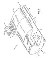
- FIG. 1 illustrates a mailing machine having a transport method and system according to the present invention
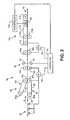
- FIG. 2 illustrates a simplified schematic diagram of a transport system in accordance with the present invention
- FIG. 3 illustrates a portion of the transport system shown in Fig. 2;
- FIG. 4 illustrates an adaptive velocity control of a mail piece according to the present invention
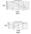
- FIG. 5 illustrates a linear increase for gap time for shorter mail pieces according to an embodiment of the present invention
- FIG. 6 illustrates a linear increase for gap time for longer mail pieces according to an embodiment of the present invention
- FIG. 7 illustrates in block diagram form the closed-loop control approach of the present invention
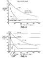
- FIG. 8 illustrates an example of a dwell velocity range for the adaptive velocity control of a mail piece according to the present invention
- FIG. 9 illustrates three discrete dwell velocities within the dwell velocity range of Fig. 8 according to an embodiment of the present invention.
- FIGS. 10A and 10B illustrate in flow diagram form the adaptive velocity control according to an embodiment of the present invention utilizing the three dwell velocities illustrated in Fig. 9.
- the following describes a mailing system with a transport for transporting mail pieces through the mailing system.
- the length of a mail piece is measured and a desired gap time between the mail piece and a subsequent mail piece is calculated.
- the desired gap time is proportional to the measured length of the mail piece, and provides for optimal throughput while still being within the necessary functional constraints of the mailing machine.
- the gap time between the mail piece and the subsequent mail piece is measured, and a difference between the desired gap time and measured gap time is calculated.
- the velocity of the subsequent mail piece is adaptively controlled to decrease the difference between the desired gap time and the measured gap time such that the measured gap time is adjusted to be approximately equal to the desired gap time, thereby optimizing throughput of the mailing system.
- a dwell time during which the subsequent mail piece is transported at a selected dwell velocity is determined to correct the difference between the desired gap time and the measured gap time.
- the dwell velocity can be selected based upon the amount of difference between the desired gap time and measured gap time.
- the subsequent mail piece is transported at the selected dwell velocity for the determined dwell time, thereby decreasing the difference between the desired gap time and measured gap time.
- Mailing machine 10 comprises a base unit, designated generally by the reference numeral 12, the base unit 12 having a mail piece input end, designated generally by the reference numeral 14 and a mail piece output end, designated generally by the reference numeral 16.
- a control unit 18 is mounted on the base unit 12, and includes one or more input/output devices, such as, for example, a keyboard 20 and a display device 22.
- One or more cover members 24 are pivotally mounted on the base 12 so as to move from the closed position shown in Fig. 1 to an open position (not shown) so as to expose various operating components and parts for service and/or repair as needed.
- the base unit 12 further includes a horizontal feed deck 30 which extends substantially from the input end 14 to the output end 16.
- a plurality of nudger rollers 32 are suitably mounted under the feed deck 30 and project upwardly through openings in the feed deck so that the periphery of the rollers 32 is slightly above the upper surface of the feed deck 30 and can exert a forward feeding force on a succession of mail pieces placed in the input end 14.
- a vertical wall 34 defines a mail piece stacking location from which the mail pieces are fed by the nudger rollers 32 along the feed deck 30 and into a transport system as illustrated in Fig. 2.
- the transport system (Fig. 2) transports the mail pieces through one or more modules, such as, for example, a separator module and moistening/sealing module. Each of these modules is located generally in the area indicated by reference numeral 36.
- the mail pieces are then passed to a metering/printing module located generally in the area indicated by reference numeral 38.
- Transport system 50 could be used, for example to transport a mail piece through the mailing machine 10 as illustrated in Fig. 1.
- Controller 52 is coupled to a pair of motors M1 and M2, designated 80 and 82, respectively.
- Controller 52 is also coupled to a sensor module 90.
- a separator module 60 receives a stack of mail pieces (not shown) from nudger rollers 32 and separates and feeds them at variable speed in a seriatim fashion (one at a time) in a path of travel along the feed deck 30 as indicated by arrow A.
- a conveyor apparatus 100 Downstream from the path of travel, a conveyor apparatus 100 feeds the mail pieces at a constant speed in the path of travel along the deck 30 past a print head module 102 so that a postage indicia can be printed on each mail piece.
- the print head module 102 is of an ink jet print head type having a plurality of ink jet nozzles (not shown) for ejecting droplets of ink in response to appropriate signals from the print head controller 104, which is coupled to the controller 52.
- Sensors (not shown) within the conveyor apparatus 100 provide signals to the controller 52 indicating the position of a mail piece. Controller 52 then prompts the print head controller 104 to begin printing at the appropriate time when a mail piece is properly positioned.
- the separator module 60 includes a feeder assembly 62 and a retard assembly 64 which work cooperatively to separate a batch of mail pieces (not shown) and feed them one at a time to a pair of take-away rollers 78a, 78b.
- the feeder assembly 62 includes a pair of rollers 66a, 66b and an endless belt 68 around them.
- the feeder assembly 60 is operatively connected to a motor M1 80 by any suitable drive train which causes the endless belt 68 to rotate clockwise so as to feed the envelopes in the direction indicated by arrow A.
- Motor 80 is also drives the nudger rollers 32.
- the retard assembly 64 includes a pair of rollers 70a, 70b having an endless belt 72 around them.
- the retard assembly 64 is operatively connected to any suitable drive means (not shown) which causes the endless belt 72 to rotate clockwise so as to prevent the upper mail pieces in the batch of mail pieces from reaching the take-away rollers 78a, 78b. In this manner, only the bottom mail piece in the stack of mail pieces advances to the take-away rollers 78a, 78b.
- any suitable drive means not shown
- the retard assembly 64 may be operatively coupled to the same motor 80 as the feeder assembly 62.
- separator module 60 Since the details of the separator module 60 are not necessary for an understanding of the present invention, no further description will be provided. However, an example of a separator module suitable for use in conjunction with the present invention is described in U.S. Patent Number 4,978,114, entitled REVERSE BELT SINGULATING APPARATUS.
- the first set of take-away rollers 78a, 78b are located adjacent to and downstream in the path of travel from the separator module 60.
- the take-away rollers 78a, 78b are operatively connected to motor 80 by any suitable drive train (not shown).
- any suitable drive train not shown.
- motor 80 generates a velocity V 1 at the feeder assembly 62 and velocity V 2 at the take-away rollers 78a, 78b, where V 2 is greater than V 1 .
- the differential between V 1 and V 2 is not greater than 3%, thereby ensuring a smooth transition of mail pieces from the feeder assembly 62 to the take-away rollers 78a, 78b. Additionally, it is also preferable that the take-away rollers 78a, 78b have a very positive nip so that they dominate control over the mail piece. Consistent with this approach, the nip between the feeder assembly 62 and the retard assembly 64 is suitably designed to allow some degree of slippage.
- the transport system 50 further includes a sensor module 90 which is downstream of take-away rollers 78a, 78b.
- the sensor module 90 is of any conventional optical type which includes a light emitter 92 and a light detector 94.
- the light emitter 92 and the light detector 94 are located in opposed relationship on opposite sides of the path of travel so that the mail pieces pass between them. By measuring the amount of light that the light detector 94 receives, the presence or absence of a mail piece can be determined.
- the sensor module 90 by detecting the leading and trailing edges of a mail piece, the sensor module 90 provides signals to the controller 52 which are used to determine the length of the mail piece that has just passed through the sensor module 90. The amount of time that passes between the lead edge detection and the trail edge detection, along with the speed at which the mail piece is being fed, can be used to determine the length of the mail piece. Additionally, the sensor module 90 measures the gap time between mail pieces by detecting the trailing edge of a first mail piece and the leading edge of a subsequent mail piece. Alternatively, an encoder system (not shown) can be used to measure the length of a mail piece by counting the number of encoder pulses which are directly related to a known amount of rotation of the take-away rollers 78a, 78b.
- a second set of take-away rollers 96a, 96b are located downstream in the path of travel from the first set of take-away rollers 78a, 78b.
- the take-away rollers 96a, 96b are operatively connected to the motor 82 by any suitable drive train (not shown).
- the moistening fluid applicator of a moistening system (not shown) is located between the take-away rollers 78a, 78b and take-away rollers 96a, 96b.
- Take-away rollers 96a, 96b can thus act as a sealing roller for the mail pieces to compress the moistened flap and body together for sealing.
- the take-away roller assemblies such that the take-away rollers 96a, 96b operate at a higher speed than the take-away rollers 78a, 78b.
- motor 80 generates a velocity V 2 at the take-rollers 78a, 78b
- motor 82 could generate a velocity V 3 at the take-away rollers 96a, 96b, where V 3 is greater than V 2 .
- the differential between V 2 and V 3 is not greater than 3%, thereby ensuring a smooth transition of mail pieces from the take-away rollers 78a, 78b to the take-away rollers 96a, 96b.
- Mail pieces are passed from the second set of take-away rollers 96a, 96b to the conveyor apparatus 100 for printing.
- the conveyor apparatus 100 includes an endless belt 110 looped around a drive roller 112 and an encoder roller 114 which is located downstream in the path of travel from the drive roller 112 and proximate to the print head module 102.
- the drive roller 112 and the encoder roller 114 are substantially identical and are fixably mounted to respective shafts (not shown) which are in turn rotatively mounted to any suitable structure (not shown) such as a frame.
- the drive roller 112 is operatively connected to motor 82 by any conventional means such as intermeshing gears (not shown) or a timing belt (not shown) such that the speed of the endless belt is controlled by motor 82, via signals from the controller 52, to advance mail pieces past the print head module 102 for printing and out of the mailing machine 10 at the output end 16.
- the velocity of the conveyor apparatus 100 must be constant to ensure proper printing by the print head module 102, and preferably operates at a higher speed than the take-away rollers 96a, 96b.
- motor 82 could generate a velocity V 4 at the conveyor apparatus 100, where V 4 is greater than V 3 .
- the differential between V 3 and V 4 is not greater than 3%, thereby ensuring a smooth transition of mail pieces from the take-away rollers 96a, 96b to the conveyor apparatus 100.
- the velocity V 4 of the conveyor apparatus 100 may be, for example, set at 35 inches per second (ips) (88.9 cm/s). This value, of course, is dependent upon the characteristics and requirements of the print head module 102.
- the conveyor apparatus 100 further includes a plurality of idler rollers 116a and a corresponding plurality of normal force rollers 116b (only one pair shown for clarity).
- the idler rollers 116a are rotatively mounted to any suitable structure (not shown) along the path of travel between the drive roller 112 and the encoder roller 114.
- the normal force rollers 116b are located in opposed relationship and biased toward the idler rollers 116a.
- the normal force rollers 116b work to bias the mail piece against a registration plate (not shown). This is commonly referred to as top surface registration which is beneficial for ink jet printing. Any variation in thickness of the mail piece is taken up by the deflection of the normal force rollers 116b.
- the distance between the print head module 102 and the top surface of the mail piece is constant regardless of the thickness of the mail piece.
- the distance is optimally set to a desired value to achieve quality printing.
- the distance between the separator module 60 and take-away rollers 78a, 78b, between the take-away rollers 78a, 78b and take-away rollers 96a, 96b, and between take-away rollers 96a, 96b and conveyor apparatus 100 is such that the shortest mail piece being transported through the transport system 50 is always under positive control of at least one of these components.
- the distance between any two adjacent components is preferably less than this value.
- any mail piece that is being transported by the transport system 50 will always be under positive control of at least one of the separator module 60, the take-away rollers 78a, 78b, the take-away rollers 96a, 96b, or the conveyor apparatus 100.
- controller 52 which may be any suitable combination of hardware, firmware and software. Controller 52 may include one or more general processors or special purpose processors.
- the operation of the mailing machine 10, and thus the transport system 50 is optimized for handling #10 envelopes (9.5 inches or 24.1 cm long), which are the most prevalent for use in business mailings.
- the throughput of the mailing machine 10 can be, for example, 170 letters per minute (Ipm), not including any maintenance cycle for the print head module 102.
- the throughput is a matter of design choice and can be set at any desired limit within the constraints previously described.
- the throughput including the maintenance cycle will be slightly less.
- Mail pieces shorter than 9.5 inches (24.1 cm) must have the same throughput as #10 mail pieces to provide sufficient time for indicium generation, while mail pieces longer than 9.5 inches (24.1 cm) must have the maximum possible throughput within the constraints imposed by the replenishment time required for the moistening fluid applicator.
- the transport system 50 is configured, i.e., velocities V 1 , V 2 , V 3 and V 4 are selected, such that when processing #10 envelopes (9.5 inches or 24.1 cm in length), a gap time of 50 msec is provided between mail pieces.
- Controller 52 performs an adaptive velocity control according to the present invention to adjust the gap time and create a desired gap between mail pieces as will be further described with respect to Figs. 3-7.
- a portion of the transport system 50 is illustrated, and specifically the portion including the take-away rollers 78a, 78b and take-away rollers 96a, 96b.
- the adaptive velocity control of the present invention occurs between the take-away rollers 78a, 78b and take-away rollers 96a, 96b as the speed of motor 80 can be regulated and this is the area where control of the mail piece transitions between motor 80 and motor 82.
- the position of the take-away rollers 78a, 78b is designated x 1
- the position of the sensor module 90 is designated x 2
- the position of the take-away rollers 96a, 96b is designated x 4 .
- the position of a moistening fluid applicator is designated x 3 , and is between x 2 and x 4 .
- the velocity of take-away rollers 78a, 78b is nominally V 2
- the velocity of take-away rollers 96a, 96b is nominally V 3 .
- the distance D between the sensor module 90 and take-away rollers 96a, 96b, defined as x 4 -x 2 is the area in which the adaptive velocity control of the present invention preferably occurs.
- a mail piece must be traveling at velocity V 2 before entering the take-away rollers 96a, 96b to ensure a smooth transition without any buckling or tearing of the mail piece.
- the gap time between a first mail piece and a subsequent second mail piece is adjusted utilizing an adaptive velocity control of the second mail piece according to the present invention that occurs in the distance D between the sensor module 90 and the take-away rollers 96a, 96b.
- This is performed by decelerating (a D ) the second mail piece for some time period, DecelTime, and some distance, DecelDist, to a dwell velocity V D for a determined period of time, DwellTime, and distance, DwellDist, and then accelerating (a A ) the second mail piece for some period of time, AccelTime, and distance, AccelDist, back to velocity V 2 before the second mail piece enters the take-away rollers 96a, 96b.
- the decelaration, a D , and acceleration, a A are not greater than 9.81 m/s 2 (386.22 ips 2 ).
- AdjustTime DesGapTime - MeasGapTime + Time ⁇ V 2
- Table 1 below describes the parameters used in the above equations (1)-(25).
- the transport system 50 is configured such that when processing #10 envelopes (9.5 inches or 24.1 cm in length), a gap time of 50 msec is provided between mail pieces. This provides a sufficient replenishment time for the moistening fluid applicator. Longer mail pieces must have a larger time gap, as more time is needed for replenishment, while shorter mail pieces must also have a larger gap time to maintain the throughput requirement.
- the mailing machine 10 is designed for a throughput of 170 Ipm for #10 envelopes, then the throughput for the longest mail piece that can be processed by mailing machine 10, such as, for example, flats having a length of 13 inches (33.0 cm), would be around 100 Ipm.
- Mail pieces shorter than #10 envelopes should have the same throughput as #10 envelopes as discussed above.
- the gap between mail pieces will linearly increase for both shorter and longer mail pieces than #10 envelopes.
- Fig. 5 illustrates one example of a linear increase in gap time for mail pieces shorter than 9.5 inches (24.1 cm) as the length of the mail piece decreases from 9.5 inches (24.1 cm) to 5 inches (12.7 cm).
- the throughput remains at 170 Ipm, with a cycle time of 353 msec per mail piece.
- a mail piece that has a length of 9.5 inches (24.1 cm) has a gap time of 50 msec between it and the subsequent following mail piece (as noted above), but a mail piece that has a length of 5 inches (12.7 cm) requires a gap time of 184 msec between it and a subsequent following mail piece.
- the desired gap time will ensure that processing time of the mail piece is within the constraints imposed by the different modules of the mailing machine 10.
- DesGapTime m SHORT ⁇ MeasLength + c SHORT
- the desired gap time is in milliseconds (msec)
- m SHORT and c SHORT are dependent upon the speed of response for the replenishment time of the moistening fluid applicator
- m SHORT could have a value of -29.71
- c SHORT could have a value of 332.24.
- Fig. 6 illustrates one example of a linear increase in gap time for a mail piece longer than 9.5 inches (24.1 cm) as the length of the mail piece increases from 9.5 inches (24.1 cm) to 13 inches (33.0 cm), with a throughput of 100 Ipm for 13 inch (33.0 cm) mail pieces.
- the cycle time for 13 inch mail pieces is 600 msec.
- a mail piece that has a length of 9.5 inches (24.1 cm) has the gap time of 50 msec between it and the subsequent following mail piece (as noted above), but a mail piece that has a length of 13 inches (33.0 cm) requires a gap time of 202 msec between it and a subsequent following mail piece.
- DesGapTime m LONG ⁇ MeasLength + c LONG
- the desired gap time is in milliseconds (msec)
- m LONG and c LONG are dependent upon the speed of response for the replenishment time of the moistening fluid applicator
- m LONG could have a value of 43.35
- c LONG could have a value of 361.80.
- the desired gap time that follows a mail piece is directly proportional to the measured length of the mail piece for all mail piece lengths.
- the control system of the present invention is a heuristic closed-loop control approach as illustrated in Fig. 7.
- the desired gap time, DesGapTime, to follow the mail piece can be calculated using either equation (26) or (27) above, depending upon the measured length of the mail piece.
- the actual gap time between the mail piece and a subsequent mail piece, MeasGapTime is also determined, utilizing sensor module 90 as described above, and thus the gap time difference variable (GapTimeDiff) can be calculated using equation (4) above.
- a suitable dwell velocity, V D can be selected by control logic, e.g., controller 52, and applied to the appropriate portion of the transport control, i.e., motor 80, to provide a dwell time, DwellTime, for the subsequent mail piece that will correct the measured gap time to be equal to the desired gap time, utilizing the relationship given in equation (25) above.
- the dwell time, DwellTime is preferably greater than some minimum amount, such as, for example, 4 msec, since any difference between the desired gap time and measured gap time of less than 4 msec is substantially inconsequential and may not be able to be adjusted any further due to electro-mechanical limitations of the transport system 50.
- the distance traveled during the gap correction is preferably less than the maximum distance allowed for correction, D C .
- the maximum distance allowed for correction will be slightly less than the distance D illustrated in Fig.
- the deceleration, a D , and acceleration, a A is preferably less than or equal to gravitational acceleration, G, i.e., 9.81 m/s 2 (386.22 ips 2 ).
- V 2 should be greater than V D which should be greater than or equal to zero.
- the correction of the measured gap time should occur only for mail pieces having a different length than #10 envelopes, i.e. 9.5 inches (24.1 cm). Therefore, there is preferably a defined tolerance to cover measurement errors when measuring the length of a mail piece that indicates a safe operation bandwidth for #10 envelopes. For example, the measurement tolerance could be ⁇ 0.3 inches ( ⁇ 7.6 mm).
- a dwell velocity, V D An exemplary selection process of a dwell velocity, V D , will now be described with respect to Fig. 8, which illustrates one example of a range between a maximum dwell velocity curve, Maximum V D , generally designated by reference numeral 140, and a minimum dwell velocity curve, Minimum V D , generally designated by the reference numeral 142.
- This range can be selected as a function of the difference between the desired and measured gap time, GapTime Diff, using the above constraints.
- the maximum dwell velocity curve, Maximum V D , 140 is constrained based on the distance traveled during the gap correction, DistV 2 , being less than the maximum distance allowed for correction, D C .
- the area above the maximum dwell velocity curve 140 results in this constraint being violated and is not valid.
- the minimum dwell velocity curve, Minimum V D , 142 is constrained based on the dwell time, DwellTime, being greater than 4 msec. Thus, the area below the minimum dwell velocity curve 142 results in this constraint being violated and is not valid. It should be noted that the area between the maximum dwell velocity curve 140 and minimum dwell velocity curve 142, i.e., the feasible area for the dwell velocity V D , is dependent upon the possible acceleration and deceleration values. Basically, the greater the acceleration and deceleration values, the larger the feasible area. If a dwell velocity, V D , is selected between the maximum dwell velocity curve 140 and minimum dwell velocity curve 142, it will be within the above constraints and the dwell time, DwellTime, can then be calculated using equation (25) above. It should be understood that the curves illustrated in Fig. 8 are exemplary in nature, as they are based on several parameters dictated by the characteristics of the mailing machine. Therefore, the values illustrated are not limiting on the present invention.
- the selection of only a single discrete dwell velocity V D for use in determining the dwell time may not be sufficient for all values of GapTimeDiff.
- a dwell velocity, V D of 12 ips, (30.5 cm/s) any value of GapTimeDiff that exceeds approximately 110 msec is above the maximum dwell velocity curve 140 for this dwell velocity and therefore is not valid, as the distance traveled during correction, DistV 2 , would be greater than the maximum distance allowed for correction, D C , and the correction would not be sufficient.
- the measured gap would never reach the desired gap between the mail pieces.
- the same problem is encountered for any single discrete dwell velocity, V D , utilized to calculate the dwell time.
- three discrete dwell velocities can be selected according to another embodiment as illustrated in Fig. 9.
- a third dwell velocity of 25.1 ips (63.8 cm/s) is selected to cover the range of 2 msec to 12 msec.
- any value for GapTimeDiff of 2 msec or greater is covered by the selection of one of these three dwell velocities.
- the value for GapTimeDiff exceeds a threshold of 47 msec, 7 ips (17.8 cm/s) will be selected as the dwell velocity, V D ; if the value for GapTimeDiff is less than a threshold of 12 msec, 25.1 ips (63.8 cm/s) will be selected as the dwell velocity, V D ; and if the value for GapTimeDiff is between or includes the threshold values of 12 msec and 47 msec, 18.3 ips (46.5 cm/s) will be selected as the dwell velocity, V D . It should be understood, of course, that these values are exemplary only, and the actual values selected may be different dependent upon the characteristics of the mailing machine utilizing the present invention. Recall that any difference between the desired gap time and measured gap time of less than 4 msec need not be corrected.
- Equation (25) above can be utilized to provide a dwell time, DwellTime, for the subsequent mail piece that will correct the measured gap time to be substantially equal to the desired gap time.
- Controller 52 will utilize the dwell velocity, V D , and dwell time to control the motor 80, thereby regulating the speed of the subsequent mail piece such that the desired gap time will substantially be achieved.
- a transport method and system operates to feed mixed size mail pieces in singular fashion and adaptively controls the velocity of the mail pieces such that overall system performance is optimized.
- the length of a mail piece is measured and a desired gap time between the mail piece and a subsequent mail piece is calculated.
- the gap time between the mail piece and the subsequent mail piece is measured, and a difference between the desired gap time and measured gap time is calculated.
- the velocity of the subsequent mail piece is adaptively controlled to decrease the difference between the desired gap time and the measured gap time such that the measured gap time is adjusted to be approximately equal to the desired gap time, thereby optimizing throughput of the mailing system.
- a dwell time during which the subsequent mail piece is transported at a selected dwell velocity is determined to correct the difference between the desired gap time and the measured gap time.
- a dwell velocity can be selected based upon the amount of difference between the desired gap time and measured gap time. The subsequent mail piece is transported at the dwell velocity for the determined dwell time, thereby decreasing the difference between the desired gap time and measured gap time.
- Figs. 10A and 10B there is illustrated in flow diagram form the adaptive velocity control according to an embodiment of the present invention that utilizes the three dwell velocities illustrated in Fig. 9.
- the description of Figs. 10A and 10B will be made with respect to the transport system 50 illustrated in Fig. 2.
- step 200 the length of a mail piece, hereinafter referred to as the first mail piece, is measured. This can be performed, for example, by controller 52 utilizing the sensor module 90 to detect the leading and trailing edge of the first mail piece.
- step 202 the gap time between the first mail piece (whose length was just measured) and a subsequent mail piece, hereinafter referred to as the second mail piece, is measured.
- the desired gap time between the first mail piece and the second mail piece is calculated utilizing either equation (26) or (27). If the length of the first mail piece is less than 9.5 inches (24.1 cm), equation (26) will be used. If the length of the first mail piece is greater than 9.5 inches (24.1 cm), equation (27) will be used. If the length of the first mail piece is equal to 9.5 inches (24.1 cm), either equation (26) or (27) can be used, as the desired gap time utilizing either equation will be calculated as 50 msec.
- the calculation can be performed, for example, by controller 52.
- a look up table can be employed that provides a corresponding desired gap time for different lengths of mail pieces.
- step 206 the difference between the desired gap time and the measured gap time (from step 202) is determined utilizing equation (4) above. This difference can be determined, for example, by controller 52.
- step 210 it is determined if the gap time difference calculated in step 206 is less than 4 msec. if the gap time difference is less than 4 msec, then in step 212 it is determined that no correction of the measured gap is necessary and the adaptive velocity control process ends in step 230. If the gap time difference is greater than 4 msec, then in step 214 it is determined if the gap time difference is greater than 47 msec. If the gap time difference is greater than 47 msec, then in step 216 the dwell velocity, V D , is set to 7 ips (17.8 cm/s), and the processing proceeds to step 224 (described below).
- step 218 it is determined if the gap time difference is less than 12 msec. If the gap time difference is not less than 12 msec, then in step 220 the dwell velocity, V D , is set to 18.3 ips (46.5 cm/s), and the processing proceeds to step 224 (described below). If it is determined that the gap time difference is less than 12 msec, then in step 222 the dwell velocity, V D , is set to 25.1 ips (63.8 cm/s), and the processing proceeds to step 224.
- step 224 the dwell time, DwellTime, is calculated using equation (25) above.
- the controller 52 knows the velocity control that must be performed on the second mail piece to adjust the gap between the first and second mail piece to the desired gap size.
- the velocity of the second mail piece is reduced to the selected dwell velocity, V D , via the motor 80 and take-away rollers 78a, 78b (as the second mail piece is still under the control of take-away rollers 78a, 78b) and run at the dwell velocity, V D , for the calculated dwell time.
- the velocity of the second mail piece is returned to the original velocity.
- the second mail piece is returned to its original velocity before it enters the take-away rollers 96a, 96b, thereby ensuring a smooth transition between the take-away rollers 78a, 78b and take-away rollers 96a, 96b.
- This is shown in Fig. 4, wherein the velocity is decelerated from its nominal velocity, V 2 , at the take-away rollers 78a, 78b, to the selected dwell velocity, V D , for the calculated dwell time, DwellTime, and then accelerated back to velocity V 2 before entering the take-away rollers 96a, 96b.
- the adaptive velocity control process then ends in step 230.
- the desired gap time can be achieved between the first mail piece and the second mail piece, thereby optimizing the throughput efficiency of the mailing machine 10.
- the gap time between successive mail pieces will be minimized based on the length of the first mail piece, thereby providing significant time savings as compared to conventional fixed gap or fixed pitch control systems.
- the dwell velocity could be calculated such that it is always on or very close to the maximum dwell velocity curve 140 (Fig. 8). This could be done, for example utilizing an exact function fit to obtain a formula for calculating the dwell velocity based on the difference between the desired gap time and the measured gap time.
- the formula could be an exponential or quadratic formula. Of course, this requires significant processing and may be computationally inefficient to implement.
- the dwell velocity can be selected via a piecewise linear function fit. A look-up table can be utilized to determine a particular dwell velocity specific for the difference between the desired gap and measured gap. Each dwell velocity is provided with a corresponding dwell time, such that it is not necessary to calculate the dwell time for each dwell velocity.
- the present invention was described with respect to mail pieces, the present invention is not so limited and can be utilized for transporting any type of articles where it is desired to optimize the throughput efficiency while maintaining sufficient gaps between articles.
Landscapes
- Engineering & Computer Science (AREA)
- Mechanical Engineering (AREA)
- Sheets, Magazines, And Separation Thereof (AREA)
- Controlling Sheets Or Webs (AREA)
- Sorting Of Articles (AREA)
- Delivering By Means Of Belts And Rollers (AREA)
Abstract
Claims (12)
- Procédé pour transporter une succession d'articles de manière séparée comprenant les étapes consistant à :déterminer (200) une longueur d'un premier article ;obtenir (204) un écart de temps voulu entre le premier article et un second article suivant, l'écart de temps voulu étant proportionnel à la longueur du premier article ; etréguler une vitesse du second article de sorte qu'un écart de temps entre le premier article et le second article soit sensiblement égal à l'écart de temps voulu entre le premier article et le second article, dans lequel l'étape de régulation de la vitesse du second article comprend également les étapes consistant à :mesurer (202) un écart de temps entre le premier article et le second article ;calculer (206) une différence entre l'écart de temps voulu et l'écart de temps mesuré ;choisir une vitesse de passage, qui possède un temps de passage correspondant, à partir d'une gamme de vitesses de passage en fonction de l'importance de la différence entre l'écart de temps voulu et l'écart de temps mesuré ; etdéplacer (226) le second article à la vitesse de passage pendant le temps de passage correspondant.
- Procédé selon la revendication 1, dans lequel la sélection d'une vitesse de passage comprend également les étapes consistant à :choisir (216) une première vitesse de passage si la différence entre l'écart de temps voulu et l'écart de temps mesuré est supérieure à un premier seuil prédéterminé ;choisir (220) une deuxième vitesse de passage si la différence entre l'écart de temps voulu et l'écart de temps mesuré est inférieure à un second seuil prédéterminé ; etchoisir (222) une troisième vitesse de passage si la différence entre l'écart de temps voulu et l'écart de temps mesuré n'est pas supérieure au premier seuil prédéterminé et n'est pas inférieure au second seuil prédéterminé.
- Procédé selon la revendication 1, dans lequel le déplacement du second article à la vitesse de passage comprend également les étapes consistant à :calculer (224) un temps de passage en fonction de la vitesse de passage ; etdéplacer (226) le second article à la vitesse de passage pendant le temps de passage.
- Procédé selon la revendication 1 ou la revendication 3, dans lequel le déplacement du second article comprend également les étapes consistant à :décélérer (226) le second article de façon à ce qu'il passe d'une première vitesse à la vitesse de passage ;déplacer le second article à la vitesse de passage pendant le temps de passage ; etaccélérer (228) le second article de façon à ce qu'il repasse à la première vitesse.
- Procédé selon la revendication 1, dans lequel le premier et le second articles sont des envois postaux.
- Procédé selon la revendication 1, dans lequel la régulation d'une vitesse comprend également les étapes consistant à :diminuer (226) la vitesse du second article de façon à ce qu'elle passe d'une première vitesse à une deuxième vitesse ; etaugmenter (228) la vitesse de façon à ce qu'elle repasse de la deuxième vitesse à la première vitesse.
- Système de transport pour transporter une succession d'articles de manière séparée comprenant :des moyens (90) pour déterminer une longueur d'un premier article ;des moyens (52) pour obtenir un écart de temps voulu entre le premier article et un second article suivant, l'écart de temps voulu étant proportionnel à la longueur du premier article ; etdes moyens (52) pour réguler une vitesse du second article de sorte qu'un écart de temps entre le premier article et le second article soit sensiblement égal à l'écart de temps voulu entre le premier article et le second article, dans lequel les moyens pour réguler la vitesse du second article comprennent également :des moyens (90) pour mesurer un écart de temps entre le premier article et le second article ;des moyens (52) pour calculer une différence entre l'écart de temps voulu et l'écart de temps mesuré ;des moyens (52) pour choisir une vitesse de passage, qui possède un temps de passage correspondant, à partir d'une gamme de vitesses de passage en fonction de l'importance de la différence entre l'écart de temps voulu et l'écart de temps mesuré ; etdes moyens (80) pour déplacer le second article à la vitesse de passage pendant le temps de passage correspondant.
- Système de transport selon la revendication 7, dans lequel les moyens pour sélectionner une vitesse de passage comprennent également :des moyens (52) pour choisir une première vitesse de passage, une deuxième vitesse de passage, ou une troisième vitesse de passage, la première vitesse de passage étant choisie si la différence entre l'écart de temps voulu et l'écart de temps mesuré est supérieure à un premier seuil prédéterminé, la deuxième vitesse de passage étant choisie si la différence entre l'écart de temps voulu et l'écart de temps mesuré est inférieure à un second seuil prédéterminé, et la troisième vitesse de passage étant choisie si la différence entre l'écart de temps voulu et l'écart de temps mesuré n'est pas supérieure au premier seuil prédéterminé et n'est pas inférieure au second seuil prédéterminé.
- Système de transport selon la revendication 7, dans lequel les moyens (52, 80) pour déplacer le second article à la vitesse de passage comprennent également :des moyens (52) pour calculer un temps de passage en fonction de la vitesse de passage ; etdes moyens (80) pour déplacer le second article à la vitesse de passage pendant le temps de passage.
- Système de transport selon la revendication 7 ou la revendication 9, dans lequel les moyens pour déplacer le second article comprennent également :des moyens (80) pour décélérer le second article de façon à ce qu'il passe d'une première vitesse à la vitesse de passage pendant le temps de passage ; etdes moyens (80) pour accélérer le second article de façon à ce qu'il repasse à la première vitesse.
- Système de transport selon la revendication 7, dans lequel les moyens pour réguler une vitesse comprennent également :des moyens (80) pour diminuer la vitesse du second article de façon à ce qu'il passe d'une première vitesse à une deuxième vitesse ; etdes moyens (80) pour augmenter la vitesse de façon à ce qu'elle repasse de la deuxième vitesse à la première vitesse.
- Système de transport selon l'une quelconque des revendications 7 à 11, dans lequel le premier et le second articles sont des envois postaux.
Applications Claiming Priority (5)
| Application Number | Priority Date | Filing Date | Title |
|---|---|---|---|
| US36364802P | 2002-03-11 | 2002-03-11 | |
| US363648P | 2002-03-11 | ||
| US382436 | 2003-03-06 | ||
| US10/382,436 US6685184B2 (en) | 2002-03-11 | 2003-03-06 | Transport method and system for controlling timing of mail pieces being processed by a mailing system |
| PCT/US2003/008275 WO2003086665A2 (fr) | 2002-03-11 | 2003-03-10 | Regulation du cadencement d'envois postaux en cours de traitement par un systeme postal |
Publications (3)
| Publication Number | Publication Date |
|---|---|
| EP1490281A2 EP1490281A2 (fr) | 2004-12-29 |
| EP1490281A4 EP1490281A4 (fr) | 2005-06-15 |
| EP1490281B1 true EP1490281B1 (fr) | 2007-02-28 |
Family
ID=27791758
Family Applications (1)
| Application Number | Title | Priority Date | Filing Date |
|---|---|---|---|
| EP03716684A Expired - Lifetime EP1490281B1 (fr) | 2002-03-11 | 2003-03-10 | Regulation du cadencement d'envois postaux en cours de traitement par un systeme postal |
Country Status (6)
| Country | Link |
|---|---|
| US (1) | US6685184B2 (fr) |
| EP (1) | EP1490281B1 (fr) |
| AU (1) | AU2003220383A1 (fr) |
| CA (1) | CA2479169C (fr) |
| DE (1) | DE60312141T2 (fr) |
| WO (1) | WO2003086665A2 (fr) |
Families Citing this family (22)
| Publication number | Priority date | Publication date | Assignee | Title |
|---|---|---|---|---|
| US6354583B1 (en) * | 1999-01-25 | 2002-03-12 | Bell & Howell Mail And Messaging Technologies Company | Sheet feeder apparatus and method with throughput control |
| JP2004043178A (ja) * | 2002-05-23 | 2004-02-12 | Ricoh Co Ltd | 自動原稿搬送装置および画像処理装置 |
| US6792332B1 (en) * | 2003-06-27 | 2004-09-14 | Pitney Bowes Inc. | Method for dynamic acceleration in an article transporting system |
| DE10350623B3 (de) * | 2003-10-30 | 2005-04-14 | Siemens Ag | Vorrichtung zum Vereinzeln von flachen Sendungen in stehender Position aus einem Sendungsstapel |
| FR2865832A1 (fr) * | 2004-01-30 | 2005-08-05 | Neopost Ind | Dispositif de traitement de courrier au vol |
| US20050230821A1 (en) * | 2004-04-15 | 2005-10-20 | Kheng Lee T | Semiconductor packages, and methods of forming semiconductor packages |
| JP4469671B2 (ja) * | 2004-07-09 | 2010-05-26 | 株式会社東芝 | 紙葉類取り出し装置 |
| DE102004037422B3 (de) * | 2004-07-30 | 2006-03-09 | Siemens Ag | Vereinzelungsstrecke für überlappte flache Sendungen in stehender Position |
| KR100713144B1 (ko) * | 2004-09-11 | 2007-05-02 | 삼성전자주식회사 | 자동 원고 급지장치의 급지제어방법 |
| US7581894B2 (en) * | 2006-12-29 | 2009-09-01 | Pitney Bowes Inc. | Method and system for controlling print operations in a mailpiece creation system |
| US7631869B2 (en) * | 2007-02-27 | 2009-12-15 | Bowe Bell + Howell Company | System and method for gap length measurement and control |
| US20090217833A1 (en) * | 2008-02-29 | 2009-09-03 | Goss International Americas, Inc. | Conveyor and method for changing the pitch of printed products |
| US7999206B2 (en) * | 2008-03-14 | 2011-08-16 | Siemens Industry, Inc. | Method and system for sorting of extended capability mail |
| JP4513908B2 (ja) * | 2008-07-01 | 2010-07-28 | ブラザー工業株式会社 | シート供給装置および画像形成装置 |
| JP4650564B2 (ja) * | 2008-12-12 | 2011-03-16 | コニカミノルタビジネステクノロジーズ株式会社 | シート搬送装置及びこれを備えた画像形成装置 |
| US8162468B2 (en) * | 2008-12-15 | 2012-04-24 | Pitney Bowes Inc. | System and method for registering color ink jet printing in a mailing machine |
| FR2944268B1 (fr) * | 2009-04-09 | 2011-04-15 | Solystic | Dispositif d'alimentation d'objets plats avec un synchronisateur a plusieurs motorisations |
| FR2950873B1 (fr) * | 2009-10-02 | 2011-12-16 | Neopost Technologies | Dispositif d'alimentation a separation d'enveloppes controlee |
| US8480077B2 (en) * | 2009-10-29 | 2013-07-09 | Ncr Corporation | Document processing apparatus and method of operating a document processing apparatus |
| DE202012011877U1 (de) * | 2012-12-07 | 2013-01-04 | Francotyp-Postalia Gmbh | Zuführstation |
| US8985579B1 (en) * | 2014-05-15 | 2015-03-24 | Foxlink Image Technology Co., Ltd | Paper feeding device |
| US10112420B2 (en) | 2014-09-26 | 2018-10-30 | Hewlett-Packard Development Company, L.P. | Frame length adjustment |
Family Cites Families (24)
| Publication number | Priority date | Publication date | Assignee | Title |
|---|---|---|---|---|
| US4451027A (en) | 1980-01-09 | 1984-05-29 | Burroughs Corp. | Constant spacing document feeder |
| US4331328A (en) * | 1980-06-30 | 1982-05-25 | Burroughs Corporation | Controller for a servo driven document feeder |
| US4541624A (en) | 1982-03-24 | 1985-09-17 | Nippon Electric Co., Ltd. | Flat article feeding apparatus |
| DE3424397A1 (de) * | 1984-07-03 | 1986-01-09 | Licentia Patent-Verwaltungs-Gmbh, 6000 Frankfurt | Vereinzelungseinrichtung fuer flache gegenstaende |
| US4933616A (en) | 1987-08-19 | 1990-06-12 | Pitney Bowes Inc. | Drive control system for imprinting apparatus |
| US4935078A (en) | 1988-12-28 | 1990-06-19 | Pitney Bowes Inc. | High throughput mailing maching timing |
| US5056771A (en) * | 1989-08-25 | 1991-10-15 | Lexmark International, Inc. | Apparatus for controlling interpage gaps in printers and method of interpage gap control |
| US4978114A (en) | 1989-11-14 | 1990-12-18 | Pitney Bowes Inc. | Reverse belt singulating apparatus |
| US5112038A (en) * | 1991-07-01 | 1992-05-12 | Eastman Kodak Company | Feedback control for receiver member in-track registration in an electrostatographic reproduction apparatus or the like |
| JP3049342B2 (ja) * | 1991-09-26 | 2000-06-05 | 富士ゼロックス株式会社 | 給紙装置 |
| US5295677A (en) * | 1992-08-28 | 1994-03-22 | Videojet Systems International, Inc. | Speed control for document handling system |
| US5540426A (en) * | 1993-03-10 | 1996-07-30 | Minolta Camera Kabushiki Kaisha | Method of feeding sheets and device for the same |
| US5423527A (en) * | 1993-11-05 | 1995-06-13 | Unisys Corporation | Document transport with gap adjust |
| US5575466A (en) * | 1994-11-21 | 1996-11-19 | Unisys Corporation | Document transport with variable pinch-roll force for gap adjust |
| US5924686A (en) | 1996-10-25 | 1999-07-20 | Pitney Bowes Inc. | Method for controlling the velocity of sheet separation |
| US5813327A (en) | 1996-12-26 | 1998-09-29 | Pitney Bowes Inc. | Article transport apparatus |
| DE69808407T2 (de) * | 1997-11-13 | 2003-06-26 | Hitachi, Ltd. | Papiersortiervorrichtung zum Sortieren von Papierblättern und Artikeln |
| US6076821A (en) * | 1998-09-14 | 2000-06-20 | Lexmark International, Inc. | Method and apparatus for feeding sheets |
| US6354583B1 (en) * | 1999-01-25 | 2002-03-12 | Bell & Howell Mail And Messaging Technologies Company | Sheet feeder apparatus and method with throughput control |
| US6126160A (en) * | 1999-04-12 | 2000-10-03 | Eastman Kodak Company | Sheet feeding control for image reading device |
| US6499020B1 (en) | 1999-06-07 | 2002-12-24 | Pitney Bowes Inc. | Method and device for improving the efficiency of a postage meter |
| US6533264B1 (en) * | 2001-02-09 | 2003-03-18 | Unisys Corporation | Constant space document feeder |
| US6550764B2 (en) * | 2001-02-16 | 2003-04-22 | Pitney Bowes Inc. | Apparatus and method for controlling a document-handling machine |
| US6554275B1 (en) * | 2001-12-04 | 2003-04-29 | Unisys Corporation | Method and system for document overlap/gap error detection and correction |
-
2003
- 2003-03-06 US US10/382,436 patent/US6685184B2/en not_active Expired - Lifetime
- 2003-03-10 DE DE60312141T patent/DE60312141T2/de not_active Expired - Lifetime
- 2003-03-10 AU AU2003220383A patent/AU2003220383A1/en not_active Abandoned
- 2003-03-10 WO PCT/US2003/008275 patent/WO2003086665A2/fr not_active Ceased
- 2003-03-10 CA CA 2479169 patent/CA2479169C/fr not_active Expired - Fee Related
- 2003-03-10 EP EP03716684A patent/EP1490281B1/fr not_active Expired - Lifetime
Also Published As
| Publication number | Publication date |
|---|---|
| EP1490281A2 (fr) | 2004-12-29 |
| EP1490281A4 (fr) | 2005-06-15 |
| WO2003086665A3 (fr) | 2004-01-08 |
| CA2479169A1 (fr) | 2003-10-23 |
| DE60312141D1 (de) | 2007-04-12 |
| CA2479169C (fr) | 2008-08-05 |
| DE60312141T2 (de) | 2007-10-31 |
| US20030168798A1 (en) | 2003-09-11 |
| AU2003220383A8 (en) | 2003-10-27 |
| WO2003086665A2 (fr) | 2003-10-23 |
| AU2003220383A1 (en) | 2003-10-27 |
| US6685184B2 (en) | 2004-02-03 |
Similar Documents
| Publication | Publication Date | Title |
|---|---|---|
| EP1490281B1 (fr) | Regulation du cadencement d'envois postaux en cours de traitement par un systeme postal | |
| EP0854445B1 (fr) | Appareil de transport d'articles | |
| EP1306336B1 (fr) | Correction dynamique d'intervalle pour un sous-système d'insertion | |
| US8148650B2 (en) | Mailing machine transport system with integral scale for weighing mail pieces where the contact force on the take away rollers is reduced to eliminate oscillations of the weighing platform | |
| US8178796B2 (en) | Mailing machine transport system including a guide to reduce the impact on the weighing device caused by the trailing edge of the mailpeice | |
| US6299269B1 (en) | Disabling a mailing machine when a print head is not installed | |
| US6006210A (en) | Mailing machine including dimensional rating capability | |
| US6356883B1 (en) | Mailing system having flexible printing of messages | |
| EP1388820B1 (fr) | Procédé et système pour l'affranchissement numérique à grande vitesse utilisant une technologie d'impression à basse vitesse | |
| US20080262978A1 (en) | Mail processing system including dimensional rating with true length support | |
| EP1391849B1 (fr) | Système d'impression rapide à traitement parallèle pour usage dans une machine à insérer | |
| US7814031B2 (en) | Apparatus for handling mail on the fly | |
| US6988842B2 (en) | Method and apparatus for continuous high speed digital metering using multiple print heads | |
| US5923343A (en) | Mailing machine having a registration shield with improved air flow capability during ink jet printing on envelopes | |
| CA2453938C (fr) | Methode et systeme de production automatique d'etiquettes d'indice dans un systeme de traitement du courrier | |
| EP1521218B1 (fr) | Procédé et système pour l'affranchissement numérique rapide | |
| CA2425154A1 (fr) | Systeme de mise hors fonction d'une machine de traitement du courrier sans tete d'impression |
Legal Events
| Date | Code | Title | Description |
|---|---|---|---|
| PUAI | Public reference made under article 153(3) epc to a published international application that has entered the european phase |
Free format text: ORIGINAL CODE: 0009012 |
|
| 17P | Request for examination filed |
Effective date: 20041006 |
|
| AK | Designated contracting states |
Kind code of ref document: A2 Designated state(s): AT BE BG CH CY CZ DE DK EE ES FI FR GB GR HU IE IT LI LU MC NL PT RO SE SI SK TR |
|
| AX | Request for extension of the european patent |
Extension state: AL LT LV MK |
|
| A4 | Supplementary search report drawn up and despatched |
Effective date: 20050502 |
|
| RIC1 | Information provided on ipc code assigned before grant |
Ipc: 7B 65H 43/00 A |
|
| GRAP | Despatch of communication of intention to grant a patent |
Free format text: ORIGINAL CODE: EPIDOSNIGR1 |
|
| GRAC | Information related to communication of intention to grant a patent modified |
Free format text: ORIGINAL CODE: EPIDOSCIGR1 |
|
| GRAC | Information related to communication of intention to grant a patent modified |
Free format text: ORIGINAL CODE: EPIDOSCIGR1 |
|
| GRAS | Grant fee paid |
Free format text: ORIGINAL CODE: EPIDOSNIGR3 |
|
| GRAA | (expected) grant |
Free format text: ORIGINAL CODE: 0009210 |
|
| RAP1 | Party data changed (applicant data changed or rights of an application transferred) |
Owner name: PITNEY BOWES INC. |
|
| AK | Designated contracting states |
Kind code of ref document: B1 Designated state(s): DE FR GB |
|
| REG | Reference to a national code |
Ref country code: GB Ref legal event code: FG4D |
|
| REF | Corresponds to: |
Ref document number: 60312141 Country of ref document: DE Date of ref document: 20070412 Kind code of ref document: P |
|
| ET | Fr: translation filed | ||
| PLBE | No opposition filed within time limit |
Free format text: ORIGINAL CODE: 0009261 |
|
| STAA | Information on the status of an ep patent application or granted ep patent |
Free format text: STATUS: NO OPPOSITION FILED WITHIN TIME LIMIT |
|
| 26N | No opposition filed |
Effective date: 20071129 |
|
| REG | Reference to a national code |
Ref country code: FR Ref legal event code: PLFP Year of fee payment: 14 |
|
| REG | Reference to a national code |
Ref country code: FR Ref legal event code: PLFP Year of fee payment: 15 |
|
| REG | Reference to a national code |
Ref country code: FR Ref legal event code: PLFP Year of fee payment: 16 |
|
| PGFP | Annual fee paid to national office [announced via postgrant information from national office to epo] |
Ref country code: GB Payment date: 20200327 Year of fee payment: 18 Ref country code: DE Payment date: 20200327 Year of fee payment: 18 |
|
| PGFP | Annual fee paid to national office [announced via postgrant information from national office to epo] |
Ref country code: FR Payment date: 20200325 Year of fee payment: 18 |
|
| REG | Reference to a national code |
Ref country code: DE Ref legal event code: R119 Ref document number: 60312141 Country of ref document: DE |
|
| GBPC | Gb: european patent ceased through non-payment of renewal fee |
Effective date: 20210310 |
|
| PG25 | Lapsed in a contracting state [announced via postgrant information from national office to epo] |
Ref country code: DE Free format text: LAPSE BECAUSE OF NON-PAYMENT OF DUE FEES Effective date: 20211001 Ref country code: FR Free format text: LAPSE BECAUSE OF NON-PAYMENT OF DUE FEES Effective date: 20210331 Ref country code: GB Free format text: LAPSE BECAUSE OF NON-PAYMENT OF DUE FEES Effective date: 20210310 |