EP1490295B1 - Installation et procede pour la decomposition et la purification de gaz de synthese - Google Patents
Installation et procede pour la decomposition et la purification de gaz de synthese Download PDFInfo
- Publication number
- EP1490295B1 EP1490295B1 EP03709810A EP03709810A EP1490295B1 EP 1490295 B1 EP1490295 B1 EP 1490295B1 EP 03709810 A EP03709810 A EP 03709810A EP 03709810 A EP03709810 A EP 03709810A EP 1490295 B1 EP1490295 B1 EP 1490295B1
- Authority
- EP
- European Patent Office
- Prior art keywords
- liquid
- carbon monoxide
- gas
- hydrogen
- set forth
- Prior art date
- Legal status (The legal status is an assumption and is not a legal conclusion. Google has not performed a legal analysis and makes no representation as to the accuracy of the status listed.)
- Expired - Lifetime
Links
Images
Classifications
-
- F—MECHANICAL ENGINEERING; LIGHTING; HEATING; WEAPONS; BLASTING
- F25—REFRIGERATION OR COOLING; COMBINED HEATING AND REFRIGERATION SYSTEMS; HEAT PUMP SYSTEMS; MANUFACTURE OR STORAGE OF ICE; LIQUEFACTION SOLIDIFICATION OF GASES
- F25J—LIQUEFACTION, SOLIDIFICATION OR SEPARATION OF GASES OR GASEOUS OR LIQUEFIED GASEOUS MIXTURES BY PRESSURE AND COLD TREATMENT OR BY BRINGING THEM INTO THE SUPERCRITICAL STATE
- F25J3/00—Processes or apparatus for separating the constituents of gaseous or liquefied gaseous mixtures involving the use of liquefaction or solidification
- F25J3/02—Processes or apparatus for separating the constituents of gaseous or liquefied gaseous mixtures involving the use of liquefaction or solidification by rectification, i.e. by continuous interchange of heat and material between a vapour stream and a liquid stream
- F25J3/0228—Processes or apparatus for separating the constituents of gaseous or liquefied gaseous mixtures involving the use of liquefaction or solidification by rectification, i.e. by continuous interchange of heat and material between a vapour stream and a liquid stream characterised by the separated product stream
- F25J3/0276—Processes or apparatus for separating the constituents of gaseous or liquefied gaseous mixtures involving the use of liquefaction or solidification by rectification, i.e. by continuous interchange of heat and material between a vapour stream and a liquid stream characterised by the separated product stream separation of H2/N2 mixtures, i.e. of ammonia synthesis gas
-
- C—CHEMISTRY; METALLURGY
- C01—INORGANIC CHEMISTRY
- C01B—NON-METALLIC ELEMENTS; COMPOUNDS THEREOF; METALLOIDS OR COMPOUNDS THEREOF NOT COVERED BY SUBCLASS C01C
- C01B3/00—Hydrogen; Gaseous mixtures containing hydrogen; Separation of hydrogen from mixtures containing it; Purification of hydrogen; Reversible storage of hydrogen
- C01B3/50—Separation of hydrogen or hydrogen-containing gases from gaseous mixtures, e.g. purification
- C01B3/506—Separation of hydrogen or hydrogen-containing gases from gaseous mixtures, e.g. purification at low temperatures
-
- C—CHEMISTRY; METALLURGY
- C01—INORGANIC CHEMISTRY
- C01B—NON-METALLIC ELEMENTS; COMPOUNDS THEREOF; METALLOIDS OR COMPOUNDS THEREOF NOT COVERED BY SUBCLASS C01C
- C01B3/00—Hydrogen; Gaseous mixtures containing hydrogen; Separation of hydrogen from mixtures containing it; Purification of hydrogen; Reversible storage of hydrogen
- C01B3/50—Separation of hydrogen or hydrogen-containing gases from gaseous mixtures, e.g. purification
- C01B3/52—Separation of hydrogen or hydrogen-containing gases from gaseous mixtures, e.g. purification by contacting with liquids; Regeneration of used liquids
-
- C—CHEMISTRY; METALLURGY
- C10—PETROLEUM, GAS OR COKE INDUSTRIES; TECHNICAL GASES CONTAINING CARBON MONOXIDE; FUELS; LUBRICANTS; PEAT
- C10K—PURIFYING OR MODIFYING THE CHEMICAL COMPOSITION OF COMBUSTIBLE GASES CONTAINING CARBON MONOXIDE
- C10K1/00—Purifying combustible gases containing carbon monoxide
- C10K1/04—Purifying combustible gases containing carbon monoxide by cooling to condense non-gaseous materials
-
- F—MECHANICAL ENGINEERING; LIGHTING; HEATING; WEAPONS; BLASTING
- F25—REFRIGERATION OR COOLING; COMBINED HEATING AND REFRIGERATION SYSTEMS; HEAT PUMP SYSTEMS; MANUFACTURE OR STORAGE OF ICE; LIQUEFACTION SOLIDIFICATION OF GASES
- F25J—LIQUEFACTION, SOLIDIFICATION OR SEPARATION OF GASES OR GASEOUS OR LIQUEFIED GASEOUS MIXTURES BY PRESSURE AND COLD TREATMENT OR BY BRINGING THEM INTO THE SUPERCRITICAL STATE
- F25J3/00—Processes or apparatus for separating the constituents of gaseous or liquefied gaseous mixtures involving the use of liquefaction or solidification
- F25J3/02—Processes or apparatus for separating the constituents of gaseous or liquefied gaseous mixtures involving the use of liquefaction or solidification by rectification, i.e. by continuous interchange of heat and material between a vapour stream and a liquid stream
- F25J3/0204—Processes or apparatus for separating the constituents of gaseous or liquefied gaseous mixtures involving the use of liquefaction or solidification by rectification, i.e. by continuous interchange of heat and material between a vapour stream and a liquid stream characterised by the feed stream
- F25J3/0223—H2/CO mixtures, i.e. synthesis gas; Water gas or shifted synthesis gas
-
- F—MECHANICAL ENGINEERING; LIGHTING; HEATING; WEAPONS; BLASTING
- F25—REFRIGERATION OR COOLING; COMBINED HEATING AND REFRIGERATION SYSTEMS; HEAT PUMP SYSTEMS; MANUFACTURE OR STORAGE OF ICE; LIQUEFACTION SOLIDIFICATION OF GASES
- F25J—LIQUEFACTION, SOLIDIFICATION OR SEPARATION OF GASES OR GASEOUS OR LIQUEFIED GASEOUS MIXTURES BY PRESSURE AND COLD TREATMENT OR BY BRINGING THEM INTO THE SUPERCRITICAL STATE
- F25J3/00—Processes or apparatus for separating the constituents of gaseous or liquefied gaseous mixtures involving the use of liquefaction or solidification
- F25J3/02—Processes or apparatus for separating the constituents of gaseous or liquefied gaseous mixtures involving the use of liquefaction or solidification by rectification, i.e. by continuous interchange of heat and material between a vapour stream and a liquid stream
- F25J3/0228—Processes or apparatus for separating the constituents of gaseous or liquefied gaseous mixtures involving the use of liquefaction or solidification by rectification, i.e. by continuous interchange of heat and material between a vapour stream and a liquid stream characterised by the separated product stream
- F25J3/0261—Processes or apparatus for separating the constituents of gaseous or liquefied gaseous mixtures involving the use of liquefaction or solidification by rectification, i.e. by continuous interchange of heat and material between a vapour stream and a liquid stream characterised by the separated product stream separation of carbon monoxide
-
- F—MECHANICAL ENGINEERING; LIGHTING; HEATING; WEAPONS; BLASTING
- F25—REFRIGERATION OR COOLING; COMBINED HEATING AND REFRIGERATION SYSTEMS; HEAT PUMP SYSTEMS; MANUFACTURE OR STORAGE OF ICE; LIQUEFACTION SOLIDIFICATION OF GASES
- F25J—LIQUEFACTION, SOLIDIFICATION OR SEPARATION OF GASES OR GASEOUS OR LIQUEFIED GASEOUS MIXTURES BY PRESSURE AND COLD TREATMENT OR BY BRINGING THEM INTO THE SUPERCRITICAL STATE
- F25J3/00—Processes or apparatus for separating the constituents of gaseous or liquefied gaseous mixtures involving the use of liquefaction or solidification
- F25J3/02—Processes or apparatus for separating the constituents of gaseous or liquefied gaseous mixtures involving the use of liquefaction or solidification by rectification, i.e. by continuous interchange of heat and material between a vapour stream and a liquid stream
- F25J3/0228—Processes or apparatus for separating the constituents of gaseous or liquefied gaseous mixtures involving the use of liquefaction or solidification by rectification, i.e. by continuous interchange of heat and material between a vapour stream and a liquid stream characterised by the separated product stream
- F25J3/0271—Processes or apparatus for separating the constituents of gaseous or liquefied gaseous mixtures involving the use of liquefaction or solidification by rectification, i.e. by continuous interchange of heat and material between a vapour stream and a liquid stream characterised by the separated product stream separation of H2/CO mixtures, i.e. of synthesis gas
-
- C—CHEMISTRY; METALLURGY
- C01—INORGANIC CHEMISTRY
- C01B—NON-METALLIC ELEMENTS; COMPOUNDS THEREOF; METALLOIDS OR COMPOUNDS THEREOF NOT COVERED BY SUBCLASS C01C
- C01B2203/00—Integrated processes for the production of hydrogen or synthesis gas
- C01B2203/04—Integrated processes for the production of hydrogen or synthesis gas containing a purification step for the hydrogen or the synthesis gas
- C01B2203/0415—Purification by absorption in liquids
-
- C—CHEMISTRY; METALLURGY
- C01—INORGANIC CHEMISTRY
- C01B—NON-METALLIC ELEMENTS; COMPOUNDS THEREOF; METALLOIDS OR COMPOUNDS THEREOF NOT COVERED BY SUBCLASS C01C
- C01B2203/00—Integrated processes for the production of hydrogen or synthesis gas
- C01B2203/04—Integrated processes for the production of hydrogen or synthesis gas containing a purification step for the hydrogen or the synthesis gas
- C01B2203/0465—Composition of the impurity
- C01B2203/047—Composition of the impurity the impurity being carbon monoxide
-
- C—CHEMISTRY; METALLURGY
- C01—INORGANIC CHEMISTRY
- C01B—NON-METALLIC ELEMENTS; COMPOUNDS THEREOF; METALLOIDS OR COMPOUNDS THEREOF NOT COVERED BY SUBCLASS C01C
- C01B2203/00—Integrated processes for the production of hydrogen or synthesis gas
- C01B2203/04—Integrated processes for the production of hydrogen or synthesis gas containing a purification step for the hydrogen or the synthesis gas
- C01B2203/0465—Composition of the impurity
- C01B2203/0475—Composition of the impurity the impurity being carbon dioxide
-
- C—CHEMISTRY; METALLURGY
- C01—INORGANIC CHEMISTRY
- C01B—NON-METALLIC ELEMENTS; COMPOUNDS THEREOF; METALLOIDS OR COMPOUNDS THEREOF NOT COVERED BY SUBCLASS C01C
- C01B2203/00—Integrated processes for the production of hydrogen or synthesis gas
- C01B2203/04—Integrated processes for the production of hydrogen or synthesis gas containing a purification step for the hydrogen or the synthesis gas
- C01B2203/0465—Composition of the impurity
- C01B2203/048—Composition of the impurity the impurity being an organic compound
-
- F—MECHANICAL ENGINEERING; LIGHTING; HEATING; WEAPONS; BLASTING
- F25—REFRIGERATION OR COOLING; COMBINED HEATING AND REFRIGERATION SYSTEMS; HEAT PUMP SYSTEMS; MANUFACTURE OR STORAGE OF ICE; LIQUEFACTION SOLIDIFICATION OF GASES
- F25J—LIQUEFACTION, SOLIDIFICATION OR SEPARATION OF GASES OR GASEOUS OR LIQUEFIED GASEOUS MIXTURES BY PRESSURE AND COLD TREATMENT OR BY BRINGING THEM INTO THE SUPERCRITICAL STATE
- F25J2200/00—Processes or apparatus using separation by rectification
- F25J2200/70—Refluxing the column with a condensed part of the feed stream, i.e. fractionator top is stripped or self-rectified
-
- F—MECHANICAL ENGINEERING; LIGHTING; HEATING; WEAPONS; BLASTING
- F25—REFRIGERATION OR COOLING; COMBINED HEATING AND REFRIGERATION SYSTEMS; HEAT PUMP SYSTEMS; MANUFACTURE OR STORAGE OF ICE; LIQUEFACTION SOLIDIFICATION OF GASES
- F25J—LIQUEFACTION, SOLIDIFICATION OR SEPARATION OF GASES OR GASEOUS OR LIQUEFIED GASEOUS MIXTURES BY PRESSURE AND COLD TREATMENT OR BY BRINGING THEM INTO THE SUPERCRITICAL STATE
- F25J2205/00—Processes or apparatus using other separation and/or other processing means
- F25J2205/02—Processes or apparatus using other separation and/or other processing means using simple phase separation in a vessel or drum
- F25J2205/04—Processes or apparatus using other separation and/or other processing means using simple phase separation in a vessel or drum in the feed line, i.e. upstream of the fractionation step
-
- F—MECHANICAL ENGINEERING; LIGHTING; HEATING; WEAPONS; BLASTING
- F25—REFRIGERATION OR COOLING; COMBINED HEATING AND REFRIGERATION SYSTEMS; HEAT PUMP SYSTEMS; MANUFACTURE OR STORAGE OF ICE; LIQUEFACTION SOLIDIFICATION OF GASES
- F25J—LIQUEFACTION, SOLIDIFICATION OR SEPARATION OF GASES OR GASEOUS OR LIQUEFIED GASEOUS MIXTURES BY PRESSURE AND COLD TREATMENT OR BY BRINGING THEM INTO THE SUPERCRITICAL STATE
- F25J2205/00—Processes or apparatus using other separation and/or other processing means
- F25J2205/30—Processes or apparatus using other separation and/or other processing means using a washing, e.g. "scrubbing" or bubble column for purification purposes
-
- F—MECHANICAL ENGINEERING; LIGHTING; HEATING; WEAPONS; BLASTING
- F25—REFRIGERATION OR COOLING; COMBINED HEATING AND REFRIGERATION SYSTEMS; HEAT PUMP SYSTEMS; MANUFACTURE OR STORAGE OF ICE; LIQUEFACTION SOLIDIFICATION OF GASES
- F25J—LIQUEFACTION, SOLIDIFICATION OR SEPARATION OF GASES OR GASEOUS OR LIQUEFIED GASEOUS MIXTURES BY PRESSURE AND COLD TREATMENT OR BY BRINGING THEM INTO THE SUPERCRITICAL STATE
- F25J2210/00—Processes characterised by the type or other details of the feed stream
- F25J2210/42—Nitrogen
-
- F—MECHANICAL ENGINEERING; LIGHTING; HEATING; WEAPONS; BLASTING
- F25—REFRIGERATION OR COOLING; COMBINED HEATING AND REFRIGERATION SYSTEMS; HEAT PUMP SYSTEMS; MANUFACTURE OR STORAGE OF ICE; LIQUEFACTION SOLIDIFICATION OF GASES
- F25J—LIQUEFACTION, SOLIDIFICATION OR SEPARATION OF GASES OR GASEOUS OR LIQUEFIED GASEOUS MIXTURES BY PRESSURE AND COLD TREATMENT OR BY BRINGING THEM INTO THE SUPERCRITICAL STATE
- F25J2270/00—Refrigeration techniques used
- F25J2270/90—External refrigeration, e.g. conventional closed-loop mechanical refrigeration unit using Freon or NH3, unspecified external refrigeration
- F25J2270/904—External refrigeration, e.g. conventional closed-loop mechanical refrigeration unit using Freon or NH3, unspecified external refrigeration by liquid or gaseous cryogen in an open loop
-
- Y—GENERAL TAGGING OF NEW TECHNOLOGICAL DEVELOPMENTS; GENERAL TAGGING OF CROSS-SECTIONAL TECHNOLOGIES SPANNING OVER SEVERAL SECTIONS OF THE IPC; TECHNICAL SUBJECTS COVERED BY FORMER USPC CROSS-REFERENCE ART COLLECTIONS [XRACs] AND DIGESTS
- Y02—TECHNOLOGIES OR APPLICATIONS FOR MITIGATION OR ADAPTATION AGAINST CLIMATE CHANGE
- Y02E—REDUCTION OF GREENHOUSE GAS [GHG] EMISSIONS, RELATED TO ENERGY GENERATION, TRANSMISSION OR DISTRIBUTION
- Y02E60/00—Enabling technologies; Technologies with a potential or indirect contribution to GHG emissions mitigation
- Y02E60/30—Hydrogen technology
- Y02E60/32—Hydrogen storage
-
- Y—GENERAL TAGGING OF NEW TECHNOLOGICAL DEVELOPMENTS; GENERAL TAGGING OF CROSS-SECTIONAL TECHNOLOGIES SPANNING OVER SEVERAL SECTIONS OF THE IPC; TECHNICAL SUBJECTS COVERED BY FORMER USPC CROSS-REFERENCE ART COLLECTIONS [XRACs] AND DIGESTS
- Y10—TECHNICAL SUBJECTS COVERED BY FORMER USPC
- Y10S—TECHNICAL SUBJECTS COVERED BY FORMER USPC CROSS-REFERENCE ART COLLECTIONS [XRACs] AND DIGESTS
- Y10S62/00—Refrigeration
- Y10S62/92—Carbon monoxide
-
- Y—GENERAL TAGGING OF NEW TECHNOLOGICAL DEVELOPMENTS; GENERAL TAGGING OF CROSS-SECTIONAL TECHNOLOGIES SPANNING OVER SEVERAL SECTIONS OF THE IPC; TECHNICAL SUBJECTS COVERED BY FORMER USPC CROSS-REFERENCE ART COLLECTIONS [XRACs] AND DIGESTS
- Y10—TECHNICAL SUBJECTS COVERED BY FORMER USPC
- Y10S—TECHNICAL SUBJECTS COVERED BY FORMER USPC CROSS-REFERENCE ART COLLECTIONS [XRACs] AND DIGESTS
- Y10S62/00—Refrigeration
- Y10S62/931—Recovery of hydrogen
- Y10S62/934—From nitrogen
Definitions
- the invention relates to a plant part and a method for decomposition and purification of syngas with which it becomes possible two Perform process steps in a single part of the plant.
- the partial condensation of synthesis gas and the Washing the synthesis gas with liquid nitrogen a single part of the plant carried out several purified, for further chemical syntheses recovered directly usable gases or gas mixtures.
- two purification steps in one single method combined with the raw synthesis gas Cryogenic temperatures is cooled at which the carbon monoxide from the synthesis gas can be separated.
- the remaining hydrogen is in a nitrogen scrubber column and then optionally with further Nitrogen mixed used for ammonia synthesis.
- the invention thus relates to a plant part for disassembly and cleaning of synthesis gas, which consists of a device for partial condensation synthesis gas and a nitrogen scrubber, wherein the device for nitrogen washing to the device for partial Condensation connects.
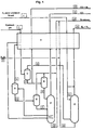
- the plant part according to the invention is shown schematically in Fig. 1.
- the composition of the drawn material streams is shown in Table I.
- the heat exchanger A is preferably a multi-path plate heat exchanger, in which the exchanger plates are generally made of aluminum consist.
- the heat exchanger A can be a variety of gas and Receive liquid feeds and keep them at preset temperatures cool or heat.
- Synthesis gas 2 is in separator B in a hydrogen-rich gas fraction 4 and a liquid phase 5 decomposed, rich in carbon monoxide and Methane is. This separation is carried out at a pressure of about 78 bar and at a Temperature of -171 ⁇ 10 ° C performed.
- the gas fraction 4 is in the heat exchanger A further cooled and then introduced into the separator C.
- the Liquid 5 is released to a pressure of about 6 bar and into the evaporator E initiated.
- the flash evaporator C is a device in which the hydrogen-rich Gas 4, which is fed from the separator B, is further separated, on the one hand into a gas (6), which consists predominantly of hydrogen and a liquid 7 consisting predominantly of carbon monoxide. This separation is carried out at a pressure of about 78 bar and at a temperature of -195 ⁇ 10 ° C performed.
- the gas 6, which is still with carbon monoxide is Ver-untica, is fed to the lower part of the scrubber G.
- the Liquid 7 is split into two streams, one for further purification and the other with excess carbon monoxide, which is still some hydrogen contains. It can be used as synthesis gas to form products such as methanol, which are made of carbon monoxide and hydrogen, be used.
- carbon monoxide 7 is placed on a Pressure of about 6 bar relaxed and introduced into the expansion evaporator D.
- the vessel D In the vessel D is absorbed by flash evaporation in the carbon monoxide Hydrogen evaporates. It can then after passing through the Heat exchanger A can be used as the fuel gas 15. The flash evaporation is at a pressure of about 6 bar and a temperature of -195 ⁇ 10 ° C performed. The resulting liquid 8 is in the distillation column F initiated.
- the liquid 5 obtained in the separator B is introduced into the flash evaporator E and the hydrogen absorbed in the liquid carbon monoxide evaporated and can then be discharged through the heat exchanger A and be recycled as fuel gas.
- This flash evaporation is at a Pressure of about 6 bar and a temperature of -171 ⁇ 10 ° C performed.
- the In the vessel E recovered liquid 9 is introduced into the distillation column F.
- the distillation column 11 is used to produce high-purity carbon monoxide with a purity above 98% by volume.
- the distillation column is stationary under a pressure of about 5 bar and has in the upper part of temperatures of about -175 ° C and in the lower part of about -155 ° C on.
- this column is one Mixture of carbon monoxide and methane from the flash evaporator E (9) and consisting essentially of carbon monoxide liquid the flash evaporator D has been initiated.
- the distillation in this Column F is carried out by heating by means of a random through a synthesis gas Composition flowed through the heat exchanger or by an am Bottom of the column existing derivative for the accumulating there liquid, which after passage through the heat exchanger A in the distillation column can be traced back (not shown in the drawing).
- the top of the separating gas in the distillation column is almost completely pure Carbon monoxide and is returned to the heat exchanger A. It is then available for syntheses in which high purity carbon monoxide is needed.
- the liquid separating at the bottom of the distillation column F is almost pure liquid methane, which relaxes at a pressure of about 1.3 bar and after passage through the heat exchanger A as a fuel gas available stands.
- the scrubbing column G is used to purify hydrogen with liquid nitrogen and for the simultaneous production of a hydrogen / nitrogen mixture.
- the wash column is under a pressure of about 77 bar and a temperature from -185 ⁇ 10 ° C. Almost pure gaseous hydrogen from the flash evaporator C is via the line 6 in the lower part of the Wash column initiated.
- Liquid nitrogen is introduced into the wash column, whereby in the wash column G, a mixture of hydrogen and Nitrogen forms the residual concentrations of carbon monoxide and argon less than 5 ppm or 150 ppm.
- the top of the wash column withdrawn product can then be mixed with other gaseous nitrogen and to a hydrogen / nitrogen molar ratio of about 3: 1, generally adjusted to a molar ratio of 2.995 and over the heat exchanger A is provided as synthesis gas for ammonia synthesis become.
- a mixture is formed liquid carbon monoxide, argon and nitrogen, which are at a pressure of 1.3 bar is relaxed and used over the heat exchanger A as the fuel gas.
- the liquid nitrogen used in the scrubbing column with a purity of 99.995% is liquefied in the heat exchanger A and as a high Pressurized nitrogen gas is fed into the wash column G.
- This Stream of nitrogen may also consist of several nitrogen streams, the be fed at different pressures in the wash column.
- the Mixture of different nitrogen streams can then be required Process pressure to be pumped.
- the task of the liquid nitrogen is to work under low pressure To cool liquid streams on the bottom of the washing column G.
- the remaining gas mixture, which consists essentially of carbon monoxide and hydrogen is the stream of synthesis gas 2, whose decomposition with the inventive System part has been described.
Landscapes
- Engineering & Computer Science (AREA)
- Chemical & Material Sciences (AREA)
- Organic Chemistry (AREA)
- Thermal Sciences (AREA)
- Physics & Mathematics (AREA)
- Mechanical Engineering (AREA)
- Combustion & Propulsion (AREA)
- General Engineering & Computer Science (AREA)
- Inorganic Chemistry (AREA)
- General Chemical & Material Sciences (AREA)
- Oil, Petroleum & Natural Gas (AREA)
- Chemical Kinetics & Catalysis (AREA)
- Separation By Low-Temperature Treatments (AREA)
- Industrial Gases (AREA)
Claims (14)
- Partie d'une installation destinée à décomposer et à nettoyer du gaz de synthèse, caractérisée en ce qu'elle comporte un dispositif pour la condensation partielle de gaz de synthèse et un dispositif pour le lavage à l'azote, le dispositif pour le lavage à l'azote étant contigu au dispositif pour la condensation partielle.
- Partie d'une installation selon la revendication 1, caractérisée en ce qu'elle comprend les dispositifs suivants qui sont reliés entre eux :un échangeur de chaleur A pour refroidir le gaz de synthèse acheminé vers la partie de l'installation ;un séparateur B relié à l'échangeur de chaleur A pour séparer, dans le gaz de synthèse 2, une fraction gazeuse 4 sensiblement constituée d'hydrogène et de monoxyde de carbone d'une fraction liquide 5 sensiblement constituée de monoxyde de carbone et de méthane ;un évaporateur C pour encore séparer, dans la fraction gazeuse 4 acheminée vers le séparateur B, une fraction gazeuse 6 constituée pour sa plus grande part d'hydrogène d'un liquide 7 constitué pour sa plus grande part de monoxyde de carbone ;un évaporateur D dans lequel l'hydrogène absorbé dans le liquide 7 s'évapore et le liquide 8 restant, qui contient essentiellement du monoxyde de carbone, est apte à être alimenté dans une colonne de distillation F ;un autre évaporateur E dans lequel l'hydrogène encore absorbé dans la fraction liquide 5 du séparateur B est éliminé par évaporation et le liquide 9, qui contient essentiellement du monoxyde de carbone et du méthane, est apte à être alimenté dans la colonne de distillation F ;une colonne de distillation F pour séparer le monoxyde de carbone gazeux et pour récupérer le méthane sous forme de liquide s'accumulant à la base de la colonne etune colonne de lavage G pour séparer par de l'azote les impuretés de la fraction gazeuse 6 de l'évaporateur C contenant essentiellement de l'hydrogène et pour réutiliser les impuretés sous forme de gaz combustible 12.
- Partie d'une installation selon les revendications 1 et 2, caractérisée en ce que l'échangeur de chaleur A est adapté pour recevoir une pluralité de conduites d'alimentation en gaz et en liquide et pour les refroidir ou les chauffer jusqu'à des températures prédéterminées.
- Partie d'une installation selon les revendications 1 à 3, caractérisée en ce que les évaporateurs C, D et E sont des évaporateurs à détente permettant d'éliminer le gaz dissous dans un liquide.
- Partie d'une installation selon les revendications 1 à 4, caractérisée en ce que la colonne de distillation F comporte un échangeur de chaleur traversé par un gaz de synthèse de n'importe quelle composition ou une conduite d'évacuation prévue à la base de la colonne pour évacuer le liquide qui s'y accumule et qui, après son passage dans l'échangeur de chaleur A, peut être recirculé dans la colonne de distillation.
- Partie d'une installation selon les revendications 1 à 5, caractérisée en ce que la colonne de lavage G comporte des conduites d'alimentation en azote gazeux et liquide.
- Procédé pour la décomposition et le nettoyage de gaz de synthèse dans la partie d'installation selon les revendications 1 à 6, caractérisé en ce que l'on effectue tout d'abord une condensation partielle du gaz de synthèse, puis un lavage avec de l'azote liquide.
- Procédé selon la revendication 7, caractérisé en ce que, dans le séparateur B, l'on procède à la séparation du gaz de synthèse 2 en une fraction gazeuse 4 essentiellement constituée d'hydrogène et de monoxyde de carbone et en une fraction liquide 5 essentiellement constituée de monoxyde de carbone et de méthane à une pression d'environ 78 bar et à une température de -171 ± 10 °C.
- Procédé selon la revendication 7 et 8, caractérisé en ce que, dans l'évaporateur C, l'on procède à la séparation dans la fraction gazeuse 4 d'une fraction gazeuse 6 constituée pour sa plus grande part d'hydrogène d'un liquide 7 constitué pour sa plus grande part de monoxyde de carbone à une pression d'environ 78 bar et à une température de -195 ± 10 °C.
- Procédé selon les revendications 7 à 9, caractérisé en ce que, dans l'évaporateur D, l'hydrogène adsorbé dans le liquide 7 est évaporé à une pression de 6 bar et à une température de -195 ± 10 °C.
- Procédé selon les revendications 7 à 10, caractérisé en ce que, dans l'évaporateur E, l'hydrogène adsorbé dans le liquide 5 est évaporé à une pression de 6 bar et à une température de -171 ± 10 °C.
- Procédé selon les revendications 7 à 11, caractérisé en ce que, dans la colonne de distillation F, l'on procède à la séparation du monoxyde de carbone à une pression d'environ 5 bar et à une température en tête de colonne d'environ -175 °C et à une température à la base de la colonne d'environ -155 °C.
- Procédé selon les revendications 7 à 12, caractérisé en ce que, dans la colonne de lavage G, l'on procède, à l'aide d'azote, à la séparation d'impuretés de la fraction gazeuse 6 contenant essentiellement de l'hydrogène à une pression d'environ 77 bar et à une température de -185 ± 10 °C.
- Procédé selon les revendications 7 à 13, caractérisé en ce que le mélange gazeux évacué de la partie supérieure de la colonne de lavage est ajusté à un rapport molaire de H2/N2 d'environ 3 : 1 par addition d'azote gazeux.
Applications Claiming Priority (3)
| Application Number | Priority Date | Filing Date | Title |
|---|---|---|---|
| DE10226210A DE10226210A1 (de) | 2002-06-13 | 2002-06-13 | Anlagenteil zur Zerlegung und Reinigung von Synthesegas |
| DE10226210 | 2002-06-13 | ||
| PCT/EP2003/003010 WO2003106331A1 (fr) | 2002-06-13 | 2003-03-22 | Installation et procede pour la decomposition et la purification de gaz de synthese |
Publications (3)
| Publication Number | Publication Date |
|---|---|
| EP1490295A1 EP1490295A1 (fr) | 2004-12-29 |
| EP1490295B1 true EP1490295B1 (fr) | 2005-08-03 |
| EP1490295B2 EP1490295B2 (fr) | 2009-11-04 |
Family
ID=29719004
Family Applications (1)
| Application Number | Title | Priority Date | Filing Date |
|---|---|---|---|
| EP03709810A Expired - Lifetime EP1490295B2 (fr) | 2002-06-13 | 2003-03-22 | Installation et procede pour la decomposition et la purification de gaz de synthese |
Country Status (7)
| Country | Link |
|---|---|
| US (1) | US7269972B2 (fr) |
| EP (1) | EP1490295B2 (fr) |
| JP (1) | JP4708017B2 (fr) |
| AU (1) | AU2003214251A1 (fr) |
| DE (2) | DE10226210A1 (fr) |
| RU (1) | RU2296704C2 (fr) |
| WO (1) | WO2003106331A1 (fr) |
Families Citing this family (11)
| Publication number | Priority date | Publication date | Assignee | Title |
|---|---|---|---|---|
| DE102006056642A1 (de) * | 2006-11-30 | 2008-06-05 | Linde Ag | Verfahren und Vorrichtung zur Gewinnung von Produkten aus Synthesegas |
| US9243842B2 (en) * | 2008-02-15 | 2016-01-26 | Black & Veatch Corporation | Combined synthesis gas separation and LNG production method and system |
| US8640495B2 (en) | 2009-03-03 | 2014-02-04 | Ait Products and Chemicals, Inc. | Separation of carbon monoxide from gaseous mixtures containing carbon monoxide |
| CN102153109B (zh) * | 2010-11-10 | 2012-09-19 | 天脊煤化工集团股份有限公司 | 鲁奇煤制氨液氮洗尾气馏份循环利用方法 |
| US20130298600A1 (en) * | 2011-01-17 | 2013-11-14 | L'air Liquide Societe Anonyme Pour I'etude Et I'exploitation Des Procedes Georges Claude | Process and apparatus for production of ammonia synthesis gas and pure methane by cryogenic separation |
| WO2013078606A1 (fr) * | 2011-11-29 | 2013-06-06 | L'air Liquide, Societe Anonyme Pour L'etude Et L'exploitation Des Procedes Georges Claude | Procédé et appareil pour la purification d'hydrogène par lavage à l'azote cryogénique et la coproduction de méthane liquide |
| FR3011069B1 (fr) * | 2013-09-24 | 2015-09-11 | Air Liquide | Procede et appareil de separation cryogenique d'un melange contenant au moins du monoxyde de carbone, de l'hydrogene et de l'azote |
| US10436505B2 (en) * | 2014-02-17 | 2019-10-08 | Black & Veatch Holding Company | LNG recovery from syngas using a mixed refrigerant |
| US20210254891A1 (en) * | 2020-02-14 | 2021-08-19 | Joseph Michael Schwartz | Method for an improved partial condensation carbon monoxide cold box operation |
| RU2751758C1 (ru) * | 2020-11-03 | 2021-07-16 | Юрий Иванович Духанин | Водородная криогенная система с колонной низкотемпературной ректификации газовой смеси |
| US12077434B2 (en) * | 2022-02-08 | 2024-09-03 | Air Products And Chemicals, Inc. | Method for producing high purity hydrogen |
Family Cites Families (17)
| Publication number | Priority date | Publication date | Assignee | Title |
|---|---|---|---|---|
| US3186145A (en) * | 1963-01-28 | 1965-06-01 | Chemical Construction Corp | Absorption of impurities from hydrogencarbon monoxide synthesis gas |
| US3872025A (en) * | 1969-10-31 | 1975-03-18 | Bethlehem Steel Corp | Production and utilization of synthesis gas |
| ZA763280B (en) * | 1975-06-05 | 1977-05-25 | Bamag Gmbh | Coal gasification process |
| GB2048848B (en) * | 1979-03-08 | 1983-08-03 | South African Wool Board | Amino acid treatment |
| US4338107A (en) * | 1980-10-30 | 1982-07-06 | Union Carbide Corporation | Wash system gas separation |
| DE3201776A1 (de) * | 1982-01-21 | 1983-09-08 | Krupp-Koppers Gmbh, 4300 Essen | Verfahren zur gleichzeitigen erzeugung von methanol- und ammoniak-synthesegas. |
| IN160585B (fr) * | 1983-02-14 | 1987-07-18 | Exxon Research Engineering Co | |
| US5104419A (en) * | 1990-02-28 | 1992-04-14 | Funk Harald F | Solid waste refining and conversion to methanol |
| US5180570A (en) * | 1992-01-23 | 1993-01-19 | Lee Jing M | Integrated process for making methanol and ammonia |
| IT1275404B1 (it) * | 1994-02-07 | 1997-08-05 | Spherilene Srl | Composizioni poliolefiniche utilizzabili per la preparazione di articoli per uso biomedicale |
| JP3415748B2 (ja) * | 1996-07-15 | 2003-06-09 | 株式会社荏原製作所 | 有機性廃棄物の二段ガス化方法及び装置 |
| EP0905127B1 (fr) * | 1997-09-20 | 2001-11-28 | Urea Casale S.A. | Procédé de production combinée d'ammoniaque et d'urée |
| GB9800692D0 (en) * | 1998-01-13 | 1998-03-11 | Air Prod & Chem | Separation of carbon monoxide from nitrogen-contaminated gaseous mixtures also containing hydrogen and methane |
| FR2775276B1 (fr) * | 1998-02-20 | 2002-05-24 | Air Liquide | Procede et installation de production de monoxyde de carbone et d'hydrogene |
| FR2775275B1 (fr) * | 1998-02-20 | 2000-05-19 | Air Liquide | Procede et installation pour la production combinee d'un melange de synthese d'ammoniac et de monoxyde de carbone |
| EP0999178B1 (fr) * | 1998-11-03 | 2006-07-26 | Ammonia Casale S.A. | Procédé pour la production de gaz de synthèse |
| DE10055818A1 (de) * | 2000-11-10 | 2002-05-23 | Ammonia Casale Sa | Verfahren zum Herstellen von Ammoniak aus einem Stickstoff-Wasserstoff-Gemisch aus Erdgas |
-
2002
- 2002-06-13 DE DE10226210A patent/DE10226210A1/de not_active Ceased
-
2003
- 2003-03-22 US US10/503,484 patent/US7269972B2/en not_active Expired - Fee Related
- 2003-03-22 EP EP03709810A patent/EP1490295B2/fr not_active Expired - Lifetime
- 2003-03-22 JP JP2004513170A patent/JP4708017B2/ja not_active Expired - Fee Related
- 2003-03-22 AU AU2003214251A patent/AU2003214251A1/en not_active Abandoned
- 2003-03-22 DE DE50300917T patent/DE50300917D1/de not_active Expired - Lifetime
- 2003-03-22 WO PCT/EP2003/003010 patent/WO2003106331A1/fr not_active Ceased
- 2003-03-22 RU RU2004136585/15A patent/RU2296704C2/ru not_active IP Right Cessation
Also Published As
| Publication number | Publication date |
|---|---|
| DE10226210A1 (de) | 2004-01-08 |
| RU2296704C2 (ru) | 2007-04-10 |
| EP1490295B2 (fr) | 2009-11-04 |
| RU2004136585A (ru) | 2005-07-10 |
| JP2005529222A (ja) | 2005-09-29 |
| WO2003106331A1 (fr) | 2003-12-24 |
| EP1490295A1 (fr) | 2004-12-29 |
| JP4708017B2 (ja) | 2011-06-22 |
| US20050076672A1 (en) | 2005-04-14 |
| AU2003214251A1 (en) | 2003-12-31 |
| US7269972B2 (en) | 2007-09-18 |
| DE50300917D1 (de) | 2005-09-08 |
Similar Documents
| Publication | Publication Date | Title |
|---|---|---|
| DE69504398T2 (de) | Verfahren und Vorrichtung für die Trennung einer Gasmischung | |
| DE69504735T2 (de) | Verfahren und Anlage zur Herstellung von Kohlenmonoxyd | |
| DE69905426T2 (de) | Verfahren zur Herstellung von Kohlenmonoxid | |
| EP1666822A1 (fr) | Installation pour la séparation cryogénique d'un mélange gazeux en particulier d'air | |
| EP1490295B1 (fr) | Installation et procede pour la decomposition et la purification de gaz de synthese | |
| DE69209572T2 (de) | Verfahren zur Herstellung von reinstem Stickstoff | |
| DE69308456T3 (de) | Extrem reiner stickstoff- und sauerstoffgenerator und verfahren | |
| DE2116326A1 (de) | Verfahren und Vorrichtung zum Trennen von Gasgemischen | |
| DE3639779A1 (de) | Verfahren zur gewinnung von co(pfeil abwaerts)2(pfeil abwaerts) aus einem co(pfeil abwaerts)2(pfeil abwaerts)-reichen erdgas | |
| DE1082287B (de) | Verfahren zur Reinigung und Verfluessigung von gasfoermigem Wasserstoff | |
| DE19541339B4 (de) | Verfahren zum Gewinnen von Kohlenmonoxid | |
| DE69008437T2 (de) | Erzeugung und Reinigung von Stickstoff. | |
| DE4325513A1 (de) | Verfahren zur Gewinnung eines hochreinen Kohlenmonoxid-Produktstromes und eines Wasserstoff-Produktstromes | |
| DE102017006552A1 (de) | Verfahren zur Gewinnung von Gasprodukten | |
| DE1815532A1 (de) | Verfahren zum Erzeugen von Kaelte | |
| DE3315930A1 (de) | Verfahren und vorrichtung zur zerlegung eines gasgemisches | |
| DE19913907A1 (de) | Verfahren und Vorrichtung zur Zerlegung von Luft durch kryogene Destillation | |
| DE1551590A1 (de) | Verfahren und Vorrichtung zum Zerlegen eines Neon und Helium enthaltenden Gasgemisches | |
| DE2040372C3 (de) | Verfahren und Vorrichtung zum Gewinnen eines heliumreichen Helium-Wasserstoff-Gemisches | |
| AT251552B (de) | Verfahren zur Gewinnung von Edelgasen aus Synthese-Restgasen | |
| DE4334256C2 (de) | Verfahren zum Gewinnen einer C¶2¶H¶4¶-reichen Produktfraktion aus einer kohlenwasserstoffhaltigen Einsatzfraktion | |
| DE2307004A1 (de) | Verfahren und vorrichtung zur gewinnung von fluessigem stickstoff | |
| DE2007441C3 (de) | Verfahren zum Gewinnen eines Wasserstoff-Stickstoff-Gemisches | |
| DE676861C (de) | Verfahren zur gleichzeitigen Gewinnung von Sauerstoff und Stickstoff hoher Reinheit | |
| WO2016128111A1 (fr) | Procédé d'extraction d'hélium |
Legal Events
| Date | Code | Title | Description |
|---|---|---|---|
| PUAI | Public reference made under article 153(3) epc to a published international application that has entered the european phase |
Free format text: ORIGINAL CODE: 0009012 |
|
| 17P | Request for examination filed |
Effective date: 20040925 |
|
| AK | Designated contracting states |
Kind code of ref document: A1 Designated state(s): AT BE BG CH CY CZ DE DK EE ES FI FR GB GR HU IE IT LI LU MC NL PT RO SE SI SK TR |
|
| AX | Request for extension of the european patent |
Extension state: AL LT LV MK |
|
| 17Q | First examination report despatched |
Effective date: 20050204 |
|
| GRAP | Despatch of communication of intention to grant a patent |
Free format text: ORIGINAL CODE: EPIDOSNIGR1 |
|
| TPAC | Observations filed by third parties |
Free format text: ORIGINAL CODE: EPIDOSNTIPA |
|
| GRAS | Grant fee paid |
Free format text: ORIGINAL CODE: EPIDOSNIGR3 |
|
| GRAA | (expected) grant |
Free format text: ORIGINAL CODE: 0009210 |
|
| RBV | Designated contracting states (corrected) |
Designated state(s): DE FR GB |
|
| AK | Designated contracting states |
Kind code of ref document: B1 Designated state(s): DE FR GB |
|
| AX | Request for extension of the european patent |
Extension state: AL LT LV MK |
|
| REG | Reference to a national code |
Ref country code: GB Ref legal event code: FG4D Free format text: NOT ENGLISH |
|
| REF | Corresponds to: |
Ref document number: 50300917 Country of ref document: DE Date of ref document: 20050908 Kind code of ref document: P |
|
| DAX | Request for extension of the european patent (deleted) | ||
| GBT | Gb: translation of ep patent filed (gb section 77(6)(a)/1977) |
Effective date: 20050928 |
|
| PLBI | Opposition filed |
Free format text: ORIGINAL CODE: 0009260 |
|
| ET | Fr: translation filed | ||
| PLAX | Notice of opposition and request to file observation + time limit sent |
Free format text: ORIGINAL CODE: EPIDOSNOBS2 |
|
| 26 | Opposition filed |
Opponent name: L'AIR LIQUIDE, S.A. A DIRECTOIRE ET CONSEIL DE S Effective date: 20060428 |
|
| PLAF | Information modified related to communication of a notice of opposition and request to file observations + time limit |
Free format text: ORIGINAL CODE: EPIDOSCOBS2 |
|
| PLAF | Information modified related to communication of a notice of opposition and request to file observations + time limit |
Free format text: ORIGINAL CODE: EPIDOSCOBS2 |
|
| PLBB | Reply of patent proprietor to notice(s) of opposition received |
Free format text: ORIGINAL CODE: EPIDOSNOBS3 |
|
| PLBP | Opposition withdrawn |
Free format text: ORIGINAL CODE: 0009264 |
|
| PLAY | Examination report in opposition despatched + time limit |
Free format text: ORIGINAL CODE: EPIDOSNORE2 |
|
| PLBC | Reply to examination report in opposition received |
Free format text: ORIGINAL CODE: EPIDOSNORE3 |
|
| PLAY | Examination report in opposition despatched + time limit |
Free format text: ORIGINAL CODE: EPIDOSNORE2 |
|
| RIC2 | Information provided on ipc code assigned after grant |
Ipc: F25J 3/02 20060101ALI20090701BHEP Ipc: C01B 3/52 20060101AFI20090701BHEP |
|
| PLAP | Information related to despatch of examination report in opposition + time limit deleted |
Free format text: ORIGINAL CODE: EPIDOSDORE2 |
|
| PUAH | Patent maintained in amended form |
Free format text: ORIGINAL CODE: 0009272 |
|
| STAA | Information on the status of an ep patent application or granted ep patent |
Free format text: STATUS: PATENT MAINTAINED AS AMENDED |
|
| RAP2 | Party data changed (patent owner data changed or rights of a patent transferred) |
Owner name: LURGI GMBH |
|
| 27A | Patent maintained in amended form |
Effective date: 20091104 |
|
| AK | Designated contracting states |
Kind code of ref document: B2 Designated state(s): DE FR GB |
|
| REG | Reference to a national code |
Ref country code: GB Ref legal event code: 732E Free format text: REGISTERED BETWEEN 20091029 AND 20091104 |
|
| REG | Reference to a national code |
Ref country code: FR Ref legal event code: CJ |
|
| REG | Reference to a national code |
Ref country code: DE Ref legal event code: R082 Ref document number: 50300917 Country of ref document: DE Representative=s name: DR. MEYER-DULHEUER & PARTNER, DE |
|
| REG | Reference to a national code |
Ref country code: DE Ref legal event code: R082 Ref document number: 50300917 Country of ref document: DE Representative=s name: DR. MEYER-DULHEUER & PARTNER, DE Effective date: 20140505 Ref country code: DE Ref legal event code: R081 Ref document number: 50300917 Country of ref document: DE Owner name: AIR LIQUIDE GLOBAL E&C SOLUTIONS GERMANY GMBH, DE Free format text: FORMER OWNER: LURGI GMBH, 60439 FRANKFURT, DE Effective date: 20140505 |
|
| REG | Reference to a national code |
Ref country code: FR Ref legal event code: PLFP Year of fee payment: 13 |
|
| PGFP | Annual fee paid to national office [announced via postgrant information from national office to epo] |
Ref country code: DE Payment date: 20150320 Year of fee payment: 13 |
|
| PGFP | Annual fee paid to national office [announced via postgrant information from national office to epo] |
Ref country code: GB Payment date: 20150319 Year of fee payment: 13 Ref country code: FR Payment date: 20150319 Year of fee payment: 13 |
|
| REG | Reference to a national code |
Ref country code: DE Ref legal event code: R119 Ref document number: 50300917 Country of ref document: DE |
|
| GBPC | Gb: european patent ceased through non-payment of renewal fee |
Effective date: 20160322 |
|
| REG | Reference to a national code |
Ref country code: FR Ref legal event code: ST Effective date: 20161130 |
|
| PG25 | Lapsed in a contracting state [announced via postgrant information from national office to epo] |
Ref country code: FR Free format text: LAPSE BECAUSE OF NON-PAYMENT OF DUE FEES Effective date: 20160331 Ref country code: GB Free format text: LAPSE BECAUSE OF NON-PAYMENT OF DUE FEES Effective date: 20160322 Ref country code: DE Free format text: LAPSE BECAUSE OF NON-PAYMENT OF DUE FEES Effective date: 20161001 |