EP1490700B1 - Dispositif et procede de controle d'un circuit electrique - Google Patents
Dispositif et procede de controle d'un circuit electrique Download PDFInfo
- Publication number
- EP1490700B1 EP1490700B1 EP03708005A EP03708005A EP1490700B1 EP 1490700 B1 EP1490700 B1 EP 1490700B1 EP 03708005 A EP03708005 A EP 03708005A EP 03708005 A EP03708005 A EP 03708005A EP 1490700 B1 EP1490700 B1 EP 1490700B1
- Authority
- EP
- European Patent Office
- Prior art keywords
- current sensor
- current
- circuit arrangement
- circuit
- switch
- Prior art date
- Legal status (The legal status is an assumption and is not a legal conclusion. Google has not performed a legal analysis and makes no representation as to the accuracy of the status listed.)
- Expired - Lifetime
Links
Images

Classifications
-
- G—PHYSICS
- G01—MEASURING; TESTING
- G01R—MEASURING ELECTRIC VARIABLES; MEASURING MAGNETIC VARIABLES
- G01R19/00—Arrangements for measuring currents or voltages or for indicating presence or sign thereof
- G01R19/0092—Measuring current only
-
- G—PHYSICS
- G01—MEASURING; TESTING
- G01R—MEASURING ELECTRIC VARIABLES; MEASURING MAGNETIC VARIABLES
- G01R35/00—Testing or calibrating of apparatus covered by the other groups of this subclass
Definitions
- the invention relates to a circuit arrangement with a circuit according to the preamble of patent claim 1 and a method for checking a circuit according to the preamble of patent claim 10.
- Circuits are used in a wide range of technical areas to supply consumers.
- the review of the power supply is an essential security aspect.
- the power supply is required for the proper functioning of the safety-related load and must therefore be checked for failure or malfunction.
- the object of the invention is to provide a circuit arrangement and a method for supplying a consumer, which enables a reliable check of the functionality of the power supply.
- the object of the invention is achieved by the circuit arrangement according to claim 1 and by the method according to claim 10.
- An essential advantage of the circuit arrangement according to the invention is that a second current sensor is provided in the circuit, and that via the second Current sensor, the current flow in the circuit is redundant detected. Thus, it is possible to check due to the second current sensor, a correct operation of the first current sensor. If, for example, the first current sensor in the embodiments of the prior art delivers a faulty signal, then this is at least not immediately recognized as a false signal. In contrast, the embodiment according to claim 1 offers the advantage of checking the circuit independently of the first current sensor. Thus, a double security for a correct monitoring of the circuit is given.
- the second current sensor can be switched into the circuit, so that the second current sensor only electrically influences the circuit when the circuit is checked.
- reliable monitoring is provided without negatively affecting the electrical properties of the circuit.
- a switch is provided, via which the second current sensor can be coupled to the circuit.
- a further switch is provided, with which the load can be disconnected from the circuit. In this way it is ensured that a circuit check is possible without the consumer having an electrical influence on the circuit.
- the second current sensor is formed in the form of a resistor.
- a voltage drop across the resistor can be detected as a measure to evaluate the current flow in the circuit.
- the use of a resistor as a current sensor is inexpensive and allows a reliable method.
- an electrical drive in particular a winding of the electric drive is checked with the circuit arrangement according to the invention.
- the circuit arrangement according to the invention is suitable for checking a safety-relevant consumer in a motor vehicle, such as an electromechanical brake.
- the second current sensor is inserted between two high-side switches and the corresponding leads to windings of an electronically commutated motor.
- a switch for connecting or disconnecting the current sensor can be dispensed with. Due to the selected connection, the current sensor has no noticeable effects on the operation of the motor.
- a cost-effective design of the circuit arrangement according to the invention is possible because of Current sensor, in particular in the form of a resistor, can be integrated in an integrated circuit.
- the second current sensor is connected in series with a winding of an electronically commutated motor when checking the current flow.
- a winding of an electronically commutated motor when checking the current flow.
- the basic principle of the invention can be used in a wide variety of technical fields.
- safety-related circuits in the field of building technology, in the field of aviation, control technology, for nuclear power plants or in the field of automotive technology can be used.
- the circuit arrangement according to the invention and the method according to the invention offer increased safety when checking a circuit, regardless of the field of application.
- Fig. 1 shows in a simplified representation of the basic principle of the circuit arrangement according to the invention. It is a DC voltage source 1 is provided which provides a fixed DC voltage. The DC voltage source is connected via a power line 2 and a current sensor 5 with an electric drive 3 in connection.
- the electric drive 3 represents, for example, an electronically commutated motor having windings 4. An electronic commutated motor is well known and described for example in the "manual of electrical systems and machines", Springer-Verlag, Egbert Hering, 1999, ISBN 3-540-65184-5 in Chapter A.5.1.3, page 203 ff ,
- the drive 3 is connected via a drive rod 6 with actuators of an electromechanical brake 7 in operative connection.
- the drive 3 controls via the drive rod 6, the operation of the electromechanical brake 7.
- the drive 3 is via a first switch 9, which is preferably designed as a field effect transistor, connectable to a ground potential.
- the first switch 9 is connected via a control line 10 to a control unit 11 in connection.
- a second current sensor 12 is connected to the power line 2.
- the second current sensor 12 may be formed in the form of a defined resistance in a simple embodiment.
- An output of the second current sensor 12 can be connected to ground via a second switch 13.
- the second switch 13 is connected via a second control line 14 to the control unit 11 in connection.
- the control unit 11 is also connected to the current sensor 5.
- a memory 15 is provided in which control information and control fields are stored.
- the control unit 11 is also connected via a third control line 16 to the drive.
- the control unit 11 controls in a known manner the phase currents for the windings 4 of the electrically commutated motor 3 according to the desired speed and the desired torque that the motor 3 is to deliver to the electromechanical brake 7. For this purpose, operating parameters of a motor vehicle 8 are taken into account, in which the circuit arrangement is arranged.
- the control unit 11 detects via the current sensor 5 via the power line 2 to the drive 3 supplied current. In this case, the current is compared with reference values and a malfunction of the power supply is detected if the detected current deviates from the reference values more than a predetermined difference value.
- the input and the output of the second current sensor 12 are connected via measuring lines 36 to an A / D converter 17.
- An output 37 of the A / D converter 17 is guided to the control unit 11.
- the control unit 11 switches in a check phase, the resistor 12 to the power line 2 by the controller 11, the second switch 13 closes and thus connects the output of the resistor 12 to ground.
- the control unit 11 preferably switches the first switch 9, which is closed during normal operation, into an open position, so that the current flow no longer flows via the drive 3, but only through the second current sensor 12.
- the control unit 11 detects both the voltage at the input and at the output of the resistor 12 during the checking phase. From the voltage drop across the resistor 12, the control unit 11 determines the current flowing through the current sensor 5.
- the control unit 11 calculates the current which is supplied to the drive 3.
- the current determined via the second current sensor 12 is compared with the current determined by the current sensor 5. If the comparison reveals that the current determined by the current sensor 5 deviates from the current which was calculated via the voltage drop of the resistor 12, the control unit 11 recognizes a malfunction of the current sensor 5 and outputs, for example, an error signal on a display system of the motor vehicle 8. In addition, the controller 11 can switch to an emergency function to ensure a safe stop of the motor vehicle 8.
- the check is preferably carried out cyclically whenever the drive 3 is not needed to actuate the electromechanical brake 7.
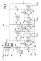
- Fig. 2 shows a further advantageous embodiment of the circuit arrangement according to the invention, which is preferably integrated in a drive circuit for an electronically commutated motor 3.
- the second current sensor 12 is integrated into the drive circuit 18.
- the motor 3 is shown only schematically in the form of the three windings 22, 25, 27.
- a DC voltage source 1 is provided which can be connected via a third switch 38 to an input of the current sensor 5.
- An output of the current sensor 5 is connected to inputs of first, second and third transistors 19, 20, 21 in connection.
- An output of the first transistor 19 is connected to an input of a first winding 22.
- An output of the first winding 22 is connected to an input of a fourth transistor 23.
- An output of the fourth transistor 23 is connected to a ground line 24 in connection.
- An output of the second transistor 20 is connected to an input of a second winding 25 in connection.
- An output of the second winding 25 is connected to an input of a fifth transistor 26 in connection.
- An output of the fifth transistor 26 is connected to the ground line 24.
- An output of the third transistor 21 is connected to an input of a third winding 27.
- An output of the third winding 27 is connected to an input of a sixth transistor 28.
- An output of the sixth transistor 28 is connected to the ground line 24.
- the outputs of the first, second and third windings 22, 25, 27 are connected via a first, second and third diode 29, 30, 31 to the input of the current sensor 5.
- the inputs of the first, second and third windings 22, 25, 27 are via a fourth, fifth and sixth diode 32, 33, 34 connected to the ground line 24. Between the ground line 24 and the input of the current sensor 5, a capacitor 35 is connected. In addition, test resistors 39 are connected in parallel with the fourth, fifth and sixth diodes 32, 33, 34, respectively.
- the control terminals of the transistors 19, 20, 21, 23, 26, 28 are connected via control lines to the controller 11.
- the controller 11 controls in a known manner the energization of the windings 22, 25, 27 to deliver via the drive rod 6 a desired speed and / or a desired torque to the electromechanical brake 7.
- the second current sensor 12 is arranged in the form of a resistor.
- the terminals of the second current sensor 12 are connected via measuring lines 36 with the A / D converter 17 of the controller 11 in connection.
- the second current sensor 12 is incorporated without additional switches in an existing circuit. Due to the arrangement of the second current sensor 12 between the high-side field-effect transistors 19, 20 of the first and second windings 22, 25, the resistance current second current sensor 12 does not interfere with normal motor commutation.
- the first transistor 19 and the fifth transistor 26 is turned on. The remaining transistors 20, 21, 23, 28 are switched off.
- a test current flows via the current sensor 5, the first transistor 19, the second current sensor 12, the second winding 25 and the fifth transistor 26 to the ground line 24.
- the current flowing through the second current sensor 12 becomes higher than the detected voltage drop across the second Current sensor 12 is calculated.
- the second current sensor 12 can also be arranged between the input of the first and the input of the third winding 22, 27 or between the input of the second and the input of the third winding 25, 27. Depending on the arrangement of the second current sensor 12 are to turn corresponding transistors in the review, so that a current flows through the second current sensor 12 and a winding.
- both the current through the current sensor 5 is detected and via the second current sensor 12.
- a defect of the first and / or the second current sensor 5, 12 can be detected.
Landscapes
- Physics & Mathematics (AREA)
- General Physics & Mathematics (AREA)
- Control Of Electric Motors In General (AREA)
- Stopping Of Electric Motors (AREA)
- Measurement Of Current Or Voltage (AREA)
Claims (12)
- Dispositif comportant un circuit électrique pour alimenter un utilisateur, notamment un moyen d'entraînement électrique, comprenant
un capteur de courant (5) installé dans le circuit électrique,
un appareil de commande (11) relié au capteur de courant (5),
l'appareil de commande (11) captant l'intensité du courant alimentant l'utilisateur par l'intermédiaire du capteur de courant (5),
caractérisé par
un second capteur de courant (12),
l'appareil de commande (11) étant relié au second capteur de courant (12),
l'appareil de commande (11) captant l'intensité du courant vers l'utilisateur par l'intermédiaire du second capteur de courant (12) et par comparaison avec l'intensité du courant captée par le capteur de courant (5) il vérifie le circuit électrique. - Dispositif selon la revendication 1,
caractérisé par
un commutateur (9),
le commutateur (9) est relié à l'appareil de commande (11) et
l'utilisateur (3) peut être coupé de l'alimentation en courant par le commutateur (9). - Dispositif selon l'une des revendications 1 ou 2,
caractérisé par
un autre commutateur (13) relié à l'appareil de commande (11) et qui peut commuter le second capteur de courant (12) dans le circuit électrique par le second commutateur (13). - Dispositif selon l'une des revendications 1 à 3,
caractérisé en ce que
le second capteur de courant (12) est réalisé sous la forme d'une résistance,
une chute de tension se détecte aux bornes de la résistance et
l'appareil de commande (11) utilise la chute de tension pour contrôler le circuit électrique. - Dispositif selon l'une des revendications 1 à 4,
caractérisé en ce que
l'utilisateur est l'enroulement (4, 22, 25, 27) d'un moyen d'entraînement électrique (3). - Dispositif selon l'une des revendications 1 à 5,
caractérisé en ce que
l'utilisateur est le moyen d'entraînement (3) d'un frein électromagnétique (7). - Dispositif selon la revendication 5,
caractérisé en ce que
le moyen d'entraînement électrique (3) comporte au moins deux enroulements (22, 25, 27),
chaque enroulement (22, 25, 27) est relié par une ligne d'alimentation propre à un commutateur d'entrée (19, 20, 21),
les commutateurs d'entrée (19, 20, 21) étant reliés à un potentiel positif,
chaque enroulement pouvant être relié par un commutateur de sortie (23, 26, 28) respectif à un potentiel négatif et
le second capteur de courant (12) est prévu entre deux lignes d'entrée. - Dispositif selon la revendication 7,
caractérisé en ce que
le second capteur de courant (12) est réalisé sous la forme d'une résistance et au moins une ligne d'entrée est reliée à une unité de mesure de tension (17). - Dispositif selon l'une des revendications 7 ou 8,
caractérisé en ce que
le second capteur de courant (12) est branché en série sur un enroulement (25) et
à partir de la chute de tension, le second capteur de courant (12) détermine l'intensité du courant passant dans le circuit électrique. - Procédé de contrôle d'une alimentation électrique d'un utilisateur alimentée en courant par une ligne d'entrée,
la ligne d'entrée étant équipée d'un premier capteur de courant (5),
caractérisé par
un second capteur de courant (12) installé en amont ou en aval de l'utilisateur (3) selon le passage du courant, et le capteur de courant (5) ainsi que le second capteur de courant (12) captent une intensité de courant et
les intensités de courant captées sont comparées et en fonction du résultat de la comparaison, on décèle un fonctionnement défectueux. - Procédé selon la revendication 10,
caractérisé en ce que
le second capteur de courant (12) est branché dans le passage du courant par l'intermédiaire d'un commutateur (13). - Procédé selon la revendication 10 ou 11,
caractérisé en ce que
l'utilisateur (3) est découplé de l'alimentation en courant par un commutateur (9).
Applications Claiming Priority (3)
| Application Number | Priority Date | Filing Date | Title |
|---|---|---|---|
| DE10212685A DE10212685A1 (de) | 2002-03-22 | 2002-03-22 | Schaltungsanordnung und Verfahren zum Überprüfen eines Stromkreises |
| DE10212685 | 2002-03-22 | ||
| PCT/DE2003/000188 WO2003081263A1 (fr) | 2002-03-22 | 2003-01-24 | Dispositif et procede de controle d'un circuit electrique |
Publications (2)
| Publication Number | Publication Date |
|---|---|
| EP1490700A1 EP1490700A1 (fr) | 2004-12-29 |
| EP1490700B1 true EP1490700B1 (fr) | 2008-06-04 |
Family
ID=28050750
Family Applications (1)
| Application Number | Title | Priority Date | Filing Date |
|---|---|---|---|
| EP03708005A Expired - Lifetime EP1490700B1 (fr) | 2002-03-22 | 2003-01-24 | Dispositif et procede de controle d'un circuit electrique |
Country Status (7)
| Country | Link |
|---|---|
| US (1) | US7005859B2 (fr) |
| EP (1) | EP1490700B1 (fr) |
| JP (1) | JP4248410B2 (fr) |
| CN (1) | CN100403035C (fr) |
| DE (2) | DE10212685A1 (fr) |
| ES (1) | ES2303893T3 (fr) |
| WO (1) | WO2003081263A1 (fr) |
Families Citing this family (19)
| Publication number | Priority date | Publication date | Assignee | Title |
|---|---|---|---|---|
| DE102005024075B4 (de) * | 2005-05-25 | 2007-04-12 | Lisa Dräxlmaier GmbH | Verfahren und Vorrichtung zur Messung eines in einem elektrischen Leiter fließenden Stroms |
| US20070205731A1 (en) * | 2006-03-01 | 2007-09-06 | Regal-Beloit Corporation | Methods and systems for dynamically braking an electronically commutated motor |
| US8005632B2 (en) | 2007-11-07 | 2011-08-23 | GM Global Technology Operations LLC | Method and apparatus for detecting faults in a current sensing device |
| KR101099811B1 (ko) * | 2009-03-03 | 2011-12-27 | 주식회사 엘지화학 | 배터리 팩의 전류측정부 이상 진단 방법 및 장치 |
| GB201013957D0 (en) * | 2010-08-20 | 2010-10-06 | Trw Ltd | Measurement circuit |
| PL2688505T3 (pl) * | 2011-03-25 | 2016-11-30 | Laser medyczny z elektroniczną przegrodą ruchomą | |
| WO2013038176A2 (fr) * | 2011-09-12 | 2013-03-21 | Metroic Limited | Mesure du courant |
| DE102011088590A1 (de) * | 2011-12-14 | 2013-06-20 | Robert Bosch Gmbh | Verfahren zur Überprüfung einer elektrischen Strommessung, Schaltung zur Durchführung des Verfahrens, Batterie und Kraftfahrzeug |
| US9234943B2 (en) | 2011-12-16 | 2016-01-12 | Lear Corporation | Method and system for battery current measurement calibration |
| DE102012215946A1 (de) * | 2012-09-07 | 2014-05-28 | Continental Teves Ag & Co. Ohg | Schaltung zum Leiten eines elektrischen Stromes |
| DE102013103307A1 (de) * | 2013-04-03 | 2014-10-23 | Hella Kgaa Hueck & Co. | Vorrichtung und Verfahren zur Überwachung einer Anhängeran schlussdose |
| GB201309825D0 (en) | 2013-06-01 | 2013-07-17 | Metroic Ltd | Current measurement |
| US9366549B2 (en) * | 2014-04-09 | 2016-06-14 | Goodrich Corporation | State sensor systems and methods |
| DE102014208680A1 (de) * | 2014-05-08 | 2015-11-12 | Robert Bosch Gmbh | Verfahren zur Überwachung von Stromsensoren |
| DE102014219807B4 (de) * | 2014-09-30 | 2019-04-04 | Volkswagen Aktiengesellschaft | Verfahren und Vorrichtung zur Prüfung einer Funktionsfähigkeit eines Stromsensors und Fahrzeug |
| CN105548684A (zh) * | 2015-12-14 | 2016-05-04 | 四川长虹电器股份有限公司 | 一种测量方法及电子设备 |
| JP6220904B2 (ja) * | 2016-01-14 | 2017-10-25 | 本田技研工業株式会社 | 蓄電装置 |
| DE102017211476A1 (de) * | 2017-07-05 | 2019-01-10 | Robert Bosch Gmbh | Vorrichtung und Verfahren zum Überprüfen einer Funktionsfähigkeit eines Systemwiderstands eines Batteriesystems |
| DE102019218007A1 (de) * | 2019-11-22 | 2021-05-27 | Robert Bosch Gmbh | Verfahren und Vorrichtung zum Überprüfen einer Funktionsfähigkeit eines als Systemwiderstand dienenden Widerstands eines Batteriesystems |
Family Cites Families (8)
| Publication number | Priority date | Publication date | Assignee | Title |
|---|---|---|---|---|
| US3934239A (en) * | 1974-09-27 | 1976-01-20 | The United States Of America As Represented By The United States Energy Research And Development Administration | Adjustable electronic load-alarm relay |
| US4706674A (en) * | 1985-06-17 | 1987-11-17 | Minnesota Mining And Manufacturing Co. | Electrical stimulator for biological tissue utilizing output current monitor |
| JPH0450550A (ja) * | 1990-06-18 | 1992-02-19 | Aisin Aw Co Ltd | 自動変速機のソレノイド駆動回路 |
| JP2861680B2 (ja) * | 1992-10-13 | 1999-02-24 | 株式会社日立製作所 | 電気自動車用故障検出法及びそれを用いたフェールセイフ制御方法 |
| DE4415386C2 (de) * | 1994-05-02 | 1998-07-02 | Knorr Bremse Systeme | Elektronisches Steuergerät für Kraftfahrzeuge, insbesondere elektronisches Bremssteuergerät |
| JPH0974794A (ja) * | 1995-09-05 | 1997-03-18 | Toyota Motor Corp | 交流電動機制御回路の異常検出装置 |
| JP2000329799A (ja) * | 1999-05-21 | 2000-11-30 | Harness Syst Tech Res Ltd | 過電流検出回路および電線保護回路 |
| GB2360335B (en) * | 2000-03-17 | 2004-06-02 | Lansing Linde Ltd | Method for operating a brake which has an electromagnet and electronic controller therefor |
-
2002
- 2002-03-22 DE DE10212685A patent/DE10212685A1/de not_active Withdrawn
-
2003
- 2003-01-24 EP EP03708005A patent/EP1490700B1/fr not_active Expired - Lifetime
- 2003-01-24 CN CNB038007282A patent/CN100403035C/zh not_active Expired - Fee Related
- 2003-01-24 WO PCT/DE2003/000188 patent/WO2003081263A1/fr not_active Ceased
- 2003-01-24 JP JP2003578945A patent/JP4248410B2/ja not_active Expired - Fee Related
- 2003-01-24 US US10/478,148 patent/US7005859B2/en not_active Expired - Fee Related
- 2003-01-24 DE DE50309954T patent/DE50309954D1/de not_active Expired - Lifetime
- 2003-01-24 ES ES03708005T patent/ES2303893T3/es not_active Expired - Lifetime
Also Published As
| Publication number | Publication date |
|---|---|
| DE50309954D1 (de) | 2008-07-17 |
| ES2303893T3 (es) | 2008-09-01 |
| CN100403035C (zh) | 2008-07-16 |
| DE10212685A1 (de) | 2004-01-08 |
| JP2005521058A (ja) | 2005-07-14 |
| US20040145373A1 (en) | 2004-07-29 |
| CN1537234A (zh) | 2004-10-13 |
| EP1490700A1 (fr) | 2004-12-29 |
| JP4248410B2 (ja) | 2009-04-02 |
| WO2003081263A1 (fr) | 2003-10-02 |
| US7005859B2 (en) | 2006-02-28 |
Similar Documents
| Publication | Publication Date | Title |
|---|---|---|
| EP1490700B1 (fr) | Dispositif et procede de controle d'un circuit electrique | |
| DE19806821C2 (de) | Störungsfeststellungseinrichtung zur Feststellung einer Störung in einem Magnetventil | |
| DE4240447C1 (de) | Elektronische Kennung und Erkennung einer fahrzeugspezifischen Kombination optionaler elektronischer Steuergeräte | |
| EP1479157A1 (fr) | Procede de reconnaissance d'erreurs pour moteurs electriques | |
| EP0277955A1 (fr) | Dispositif de surveillance pour une installation de commande electronique dans un vehicule automobile. | |
| WO2013087604A1 (fr) | Circuit de détection de court-circuit dans un système de commutateurs de puissance | |
| EP0886783A1 (fr) | Agencement de circuits permettant de reconnaitre un courant de defaut | |
| DE102007048122A1 (de) | Vorrichtung und Verfahren zur Aktorüberwachung eines zweikanalig angeschalteten sicherheitstechnischen Lastkreises | |
| EP0413893B1 (fr) | Procédé et circuit pour la surveillance d'organes de réglage à moteur électrique | |
| EP2391902B1 (fr) | Procédé de fonctionnement d'un moteur sans balais | |
| DE19611522B4 (de) | Verfahren und Vorrichtung zur Fehlererkennung bei einer Endstufenschaltungsanordnung | |
| WO2009053161A1 (fr) | Procédé d'identification d'une baisse de charge | |
| EP3612846B1 (fr) | Dispositif d'alimentation électrique pour un appareil de commande et procédé de surveillance d'une alimentation électrique | |
| DE102006030448B4 (de) | Sichere Ausgangsschaltung mit einem einkanaligen Peripherieanschluss für den Ausgang eines Bus-Teilnehmers | |
| EP1032519B1 (fr) | Cablage pour un composant de reglage, et procede de controle de ce cablage de composant de reglage | |
| DE10037495B4 (de) | Verfahren und Vorrichtung zum Erkennen einer Fehlfunktion eines Sensors oder eines Leitungsbruchs | |
| WO2015014362A1 (fr) | Procédé de détermination d'une défaillance dans un moteur électrique à commutation électronique | |
| EP1845548B1 (fr) | Dispositif, circuit et procédé destinés à la surveillance de l'isolation et du raccordement à la terre dans un système neutre isolé | |
| DE102011083217A1 (de) | Verfahren zur Überprüfung der Phasen eines elektrisch kommutierten Elektromotors | |
| EP3833589B1 (fr) | Système de contrôle pour véhicule automobile et procédé de diagnostic d'erreur dans un système de contrôle | |
| EP2876509B1 (fr) | Commande de sécurité | |
| WO2019238161A1 (fr) | Dispositif de reconnaissance d'un courant de défaut dans un actionneur comportant une unité de commande d'un véhicule | |
| DE102020210339B4 (de) | Schaltungsanordnung und Verfahren zur Fehlererkennung | |
| EP0978380B1 (fr) | Organe de calcul pour une machine à imprimer | |
| DE10040246A1 (de) | Verfahren und Vorrichtung zur Ansteuerung wenigstens eines Verbrauchers |
Legal Events
| Date | Code | Title | Description |
|---|---|---|---|
| PUAI | Public reference made under article 153(3) epc to a published international application that has entered the european phase |
Free format text: ORIGINAL CODE: 0009012 |
|
| 17P | Request for examination filed |
Effective date: 20041022 |
|
| AK | Designated contracting states |
Kind code of ref document: A1 Designated state(s): AT BE BG CH CY CZ DE DK EE ES FI FR GB GR HU IE IT LI LU MC NL PT SE SI SK TR |
|
| GRAP | Despatch of communication of intention to grant a patent |
Free format text: ORIGINAL CODE: EPIDOSNIGR1 |
|
| RBV | Designated contracting states (corrected) |
Designated state(s): DE ES FR GB |
|
| GRAS | Grant fee paid |
Free format text: ORIGINAL CODE: EPIDOSNIGR3 |
|
| GRAA | (expected) grant |
Free format text: ORIGINAL CODE: 0009210 |
|
| AK | Designated contracting states |
Kind code of ref document: B1 Designated state(s): DE ES FR GB |
|
| REG | Reference to a national code |
Ref country code: GB Ref legal event code: FG4D Free format text: NOT ENGLISH |
|
| REF | Corresponds to: |
Ref document number: 50309954 Country of ref document: DE Date of ref document: 20080717 Kind code of ref document: P |
|
| REG | Reference to a national code |
Ref country code: ES Ref legal event code: FG2A Ref document number: 2303893 Country of ref document: ES Kind code of ref document: T3 |
|
| PLBE | No opposition filed within time limit |
Free format text: ORIGINAL CODE: 0009261 |
|
| STAA | Information on the status of an ep patent application or granted ep patent |
Free format text: STATUS: NO OPPOSITION FILED WITHIN TIME LIMIT |
|
| 26N | No opposition filed |
Effective date: 20090305 |
|
| PGFP | Annual fee paid to national office [announced via postgrant information from national office to epo] |
Ref country code: FR Payment date: 20120201 Year of fee payment: 10 |
|
| PGFP | Annual fee paid to national office [announced via postgrant information from national office to epo] |
Ref country code: GB Payment date: 20120124 Year of fee payment: 10 |
|
| PGFP | Annual fee paid to national office [announced via postgrant information from national office to epo] |
Ref country code: ES Payment date: 20120124 Year of fee payment: 10 |
|
| GBPC | Gb: european patent ceased through non-payment of renewal fee |
Effective date: 20130124 |
|
| REG | Reference to a national code |
Ref country code: FR Ref legal event code: ST Effective date: 20130930 |
|
| PG25 | Lapsed in a contracting state [announced via postgrant information from national office to epo] |
Ref country code: GB Free format text: LAPSE BECAUSE OF NON-PAYMENT OF DUE FEES Effective date: 20130124 Ref country code: FR Free format text: LAPSE BECAUSE OF NON-PAYMENT OF DUE FEES Effective date: 20130131 |
|
| REG | Reference to a national code |
Ref country code: ES Ref legal event code: FD2A Effective date: 20140321 |
|
| PG25 | Lapsed in a contracting state [announced via postgrant information from national office to epo] |
Ref country code: ES Free format text: LAPSE BECAUSE OF NON-PAYMENT OF DUE FEES Effective date: 20130125 |
|
| PGFP | Annual fee paid to national office [announced via postgrant information from national office to epo] |
Ref country code: DE Payment date: 20170329 Year of fee payment: 15 |
|
| REG | Reference to a national code |
Ref country code: DE Ref legal event code: R119 Ref document number: 50309954 Country of ref document: DE |
|
| PG25 | Lapsed in a contracting state [announced via postgrant information from national office to epo] |
Ref country code: DE Free format text: LAPSE BECAUSE OF NON-PAYMENT OF DUE FEES Effective date: 20180801 |