EP1490728B1 - Procede et dispositif de modulation de la lumiere par un gaz granulaire - Google Patents
Procede et dispositif de modulation de la lumiere par un gaz granulaire Download PDFInfo
- Publication number
- EP1490728B1 EP1490728B1 EP03718707A EP03718707A EP1490728B1 EP 1490728 B1 EP1490728 B1 EP 1490728B1 EP 03718707 A EP03718707 A EP 03718707A EP 03718707 A EP03718707 A EP 03718707A EP 1490728 B1 EP1490728 B1 EP 1490728B1
- Authority
- EP
- European Patent Office
- Prior art keywords
- electrodes
- gas
- voltage
- light
- granular gas
- Prior art date
- Legal status (The legal status is an assumption and is not a legal conclusion. Google has not performed a legal analysis and makes no representation as to the accuracy of the status listed.)
- Expired - Lifetime
Links
- 238000000034 method Methods 0.000 title claims description 21
- 239000002245 particle Substances 0.000 claims abstract description 45
- 230000005684 electric field Effects 0.000 claims description 11
- 230000015572 biosynthetic process Effects 0.000 claims 1
- 239000000843 powder Substances 0.000 description 56
- 239000007789 gas Substances 0.000 description 41
- 239000000463 material Substances 0.000 description 6
- 230000001419 dependent effect Effects 0.000 description 4
- 239000011521 glass Substances 0.000 description 3
- 230000008033 biological extinction Effects 0.000 description 2
- 230000001427 coherent effect Effects 0.000 description 2
- 230000003247 decreasing effect Effects 0.000 description 2
- 239000004973 liquid crystal related substance Substances 0.000 description 2
- 239000000758 substrate Substances 0.000 description 2
- YVTHLONGBIQYBO-UHFFFAOYSA-N zinc indium(3+) oxygen(2-) Chemical compound [O--].[Zn++].[In+3] YVTHLONGBIQYBO-UHFFFAOYSA-N 0.000 description 2
- 238000010521 absorption reaction Methods 0.000 description 1
- 230000001133 acceleration Effects 0.000 description 1
- 230000002411 adverse Effects 0.000 description 1
- 238000007664 blowing Methods 0.000 description 1
- 230000015556 catabolic process Effects 0.000 description 1
- 239000004020 conductor Substances 0.000 description 1
- 238000010276 construction Methods 0.000 description 1
- 230000008878 coupling Effects 0.000 description 1
- 238000010168 coupling process Methods 0.000 description 1
- 238000005859 coupling reaction Methods 0.000 description 1
- 239000005262 ferroelectric liquid crystals (FLCs) Substances 0.000 description 1
- 230000010354 integration Effects 0.000 description 1
- 230000003993 interaction Effects 0.000 description 1
- 239000007788 liquid Substances 0.000 description 1
- 239000011159 matrix material Substances 0.000 description 1
- 229910052751 metal Inorganic materials 0.000 description 1
- 239000002184 metal Substances 0.000 description 1
- 239000003595 mist Substances 0.000 description 1
- 239000000203 mixture Substances 0.000 description 1
- 239000012811 non-conductive material Substances 0.000 description 1
- 230000003287 optical effect Effects 0.000 description 1
- 230000000149 penetrating effect Effects 0.000 description 1
- 230000000704 physical effect Effects 0.000 description 1
- 229920000642 polymer Polymers 0.000 description 1
- 238000005036 potential barrier Methods 0.000 description 1
- 230000008929 regeneration Effects 0.000 description 1
- 238000011069 regeneration method Methods 0.000 description 1
- 239000004065 semiconductor Substances 0.000 description 1
- 125000006850 spacer group Chemical group 0.000 description 1
- 238000004528 spin coating Methods 0.000 description 1
- 239000000725 suspension Substances 0.000 description 1
- 230000009182 swimming Effects 0.000 description 1
- 239000012780 transparent material Substances 0.000 description 1
Images


Classifications
-
- G—PHYSICS
- G02—OPTICS
- G02F—OPTICAL DEVICES OR ARRANGEMENTS FOR THE CONTROL OF LIGHT BY MODIFICATION OF THE OPTICAL PROPERTIES OF THE MEDIA OF THE ELEMENTS INVOLVED THEREIN; NON-LINEAR OPTICS; FREQUENCY-CHANGING OF LIGHT; OPTICAL LOGIC ELEMENTS; OPTICAL ANALOGUE/DIGITAL CONVERTERS
- G02F1/00—Devices or arrangements for the control of the intensity, colour, phase, polarisation or direction of light arriving from an independent light source, e.g. switching, gating or modulating; Non-linear optics
- G02F1/01—Devices or arrangements for the control of the intensity, colour, phase, polarisation or direction of light arriving from an independent light source, e.g. switching, gating or modulating; Non-linear optics for the control of the intensity, phase, polarisation or colour
- G02F1/165—Devices or arrangements for the control of the intensity, colour, phase, polarisation or direction of light arriving from an independent light source, e.g. switching, gating or modulating; Non-linear optics for the control of the intensity, phase, polarisation or colour based on translational movement of particles in a fluid under the influence of an applied field
- G02F1/1685—Operation of cells; Circuit arrangements affecting the entire cell
-
- G—PHYSICS
- G02—OPTICS
- G02F—OPTICAL DEVICES OR ARRANGEMENTS FOR THE CONTROL OF LIGHT BY MODIFICATION OF THE OPTICAL PROPERTIES OF THE MEDIA OF THE ELEMENTS INVOLVED THEREIN; NON-LINEAR OPTICS; FREQUENCY-CHANGING OF LIGHT; OPTICAL LOGIC ELEMENTS; OPTICAL ANALOGUE/DIGITAL CONVERTERS
- G02F2203/00—Function characteristic
- G02F2203/12—Function characteristic spatial light modulator
Definitions
- the invention relates to a method for light modulation according to the Preamble of claim 1 specified features. Furthermore, the Invention to an apparatus for carrying out the method.
- Electrophoretic displays are the charged particles in a suspension, that is, they are swimming in an electrically insulating liquid.
- the invention has for its object to propose a method and a device, to the light modulation in a simple manner and with a low constructive To be able to carry out effort.
- the method should be a fast and / or enable reliably reproducible modulation of the light and without problems different operating conditions and applications be adaptable.
- the device should process with a low cost and few components be feasible.
- the device should have a low volume and construction facilitate easy integration and customization to existing systems. Of Furthermore, by the method or the device, the switching speed of Light modulation can be improved.
- the Light of any source and wavelength, especially the coherent, parallel light of a laser, modulated, that is, its intensity is changed.
- the light is described in the following and also as “modulation cell” designated device or device coupled.
- This coupling can ever according to light source and application require a different look.
- the Process move charged particles in a gas or in a vacuum and produce a so-called “granular gas".
- granular gas which in the is essentially a homogeneous cloud of powder (mist)
- the granular gas is passed through external electrostatic forces generated on the electrically charged powder particles Act.
- the light intensity is modulated by the controlled granular gas.
- the light emerging from the cell is imaged by optics depending on the application.
- the light modulation in particular of the coherent, parallel light of a Lasers, according to the invention by means of the controlled granular gas.
- the modulation cell Depending on the exact structure of the modulation cell, a single light beam, Parts of it or even several light bundles are modulated in parallel.
- a light bundle In this case, the light irradiated into the modulation cell is referred to, which both a laser beam as well as the collimated and / or focused light of any one other light source can be.
- the apparatus can be For example, use as a variable, fast-switching gray filter, the whole Attenuates light bundles or parts thereof.
- SLM spatial Light Modulator
- two electrodes 1, 2 are at a distance z from each other in the basic modulation cell.
- an electrically charged powder 5 In the space between the two electrodes 1, 2 is an electrically charged powder 5 and an arbitrarily dense gas or a vacuum.
- the electrodes 1, 2 are coated with an optional electrically insulating layer 3, 4 of thickness d 1 or d 2 , as will be explained below.
- U 0 substantially constant voltage between the electrodes 1, 2
- the powder particles adhere to the insulating layers 3, 4.
- the light to be modulated intensity of intensity I 0 falls laterally into the cell and passes through them unhindered.
- the particles do not move synchronously because they adhere to the electrodes by a different force, ie the powder particles begin to move at different times.
- the particles move back and forth between the electrodes, interacting with each other to produce a granular gas 6.
- Q the charge
- m the mass of a powder particle.
- the voltage U 1 is preset at a frequency smaller than the cutoff frequency. The lower limit of the frequency is that frequency from which the powder particles can be moved back and forth from one to the other electrode as a function of, in particular, the abovementioned parameters.
- the incident light is absorbed / scattered by the powder particles, and only a fraction of I 1 ⁇ I 0 of the incident intensity I 0 can traverse the cell or device.
- the ratio of I 1 to I 0 is dependent on the length of the distance that travels the light through the granular gas, and the density and scattering or absorption capacity of the granular gas.
- the extinction coefficient of the granular gas and the speed with which it can be generated from the quiescent powder particles are particularly dependent on the magnitude and the time course of the applied voltage, as well as the material, the charge and the size of the individual powder particles .
- the switching speed increases with decreasing mass and increasing electrical charge of the individual particles, ie with an increase in the quotient of charge and mass Q / m.
- the switching speed increases with the strength of the electric field between the electrodes, ie with increasing voltage U 1 or decreasing distance z.
- the charged powder is endeavored by the electrical repulsion forces, a to bring as large a distance between the individual powder particles and themselves extend beyond the borders of the cell. Because particles that are not between the electrodes are located, but can not be moved, this extension must be prevented. This is done by choosing the electric field, which is shaped so that it prevents this expansion.
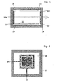
- An electric field that limits the powder to the space between the electrodes can be divided into several by the division of the electrodes 1, 2 shown in FIG Realize individual electrodes, which are independent of each other with a voltage occupy and hereinafter referred to as control and limiting electrodes become.
- the control electrodes serve to generate (turn on and off) the granular Gases, and the boundary electrodes create a potential barrier and prevent that the powder particles leave the modulation cell.
- the upper and lower electrodes each consist of a control electrode and a limiting electrode, which in this case are rectangular but, as mentioned, may have any shape depending on the application (polygon, Ellipse).
- the electrodes 7 and 8 or 9 and 10 are separated by a distance d and in this case all are covered by an electrically insulating layer 11.
- the control electrodes 7, 9 serve to generate the granular gas and the outer boundary electrodes 8, 10 ensure that the powder particles 12 can not leave the modulation cell. If, for example, the powder is positively charged, this is achieved by the limiting electrodes 8, 10 being connected positively to the control electrodes 7, 9, that is to say U 4 > U 3 and U 6 > U 5 .
- U 4 > U 3 and U 6 > U 5 By suitable choice of the voltages U 3-6 , which vary in time and with each other, thus a granular gas 12 is generated, which is essentially limited to the space between the control electrodes 7, 9.
- SLM Single Mode Modulation cell
- a Modulation cell which consists of a series of individual pixels that are independent be able to modulate parts of a light beam from each other.
- an SLM as in FIG. 4 is to be realized according to the invention.
- the cell consists in this case of eight pixein (theoretically but of any number), which can be turned on and off individually via the first control electrodes 13.
- the second lower control electrode 14 is a continuous one in this case Surface, but can also split into several control electrodes depending on the application be formed or geometrically identical to the upper control electrode.
- the Boundary electrodes 15, 16 again serve to confine the granular gas 17 to the cell.
- Each of these electrodes can independently with a voltage are occupied, whereby the granular gas 17 can be switched in each pixel.
- the light that traverses the cell in the y direction can be in each individual pixels are modulated independently.
- Light modulation in such a SLM may also include some or all of the electrodes in be divided into y-direction.
- the distance between the electrodes and each other their geometric shape depends on the desired light modulation.
- the electrodes were on two levels in the vertical Direction limited, but this is not necessarily so. You can, for example build a completely encapsulated modulation cell in which the boundary electrodes not horizontally but vertically aligned.
- Fig. 5 is a section through a represented such cell.
- the control electrodes 18, 19 generate the granular gas the powder 20, and the boundary electrodes 21, 22 in this case prevent the Sticking the powder particles on the walls of the cell and hold the powder between the control electrodes. All electrodes are of an electrically insulating Layer 23 coated. Because the light to be modulated even with a sealed cell is directed through the gap of the control electrodes, the boundary electrodes either transparent 21, e.g.
- ITO Indium zinc oxide
- the insulating layer 23 and the substrate 24 on which the boundary electrode is located in this case a transparent material.
- the dimensions of the modulation cell and the powder particles are dependent on the particular application, in particular the switching speed, which can be achieved would like to. The smaller the dimensions, the faster the granular gas can be switch and thus modulate the light and the lower the required voltage, to produce the granular gas.
- Typical distances of the electrodes z, in figure 1 are in the range of 1 mm to 0.1 mm and typical voltages for generating the Granular gases are between I000V and 50V.
- the geometric dimensions of Control and limiting electrodes can be in the range of micrometers but also Centimeters are and depend on the desired light modulation.
- the modulation cells can be easily, for example, by photolithographic Produce processes that are particularly suitable to write even small structures.
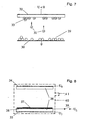
- FIG. 6 shows a preferred Possibility of realization of the modulation cell according to FIG. 3.
- the control electrode 26, (7, 9 in Fig. 3) and the limiting electrode 27 (8, 10 in Fig. 3) can separately with be supplied with a voltage.
- the optional thin insulating layer 28 (11 in FIG. 3) can be sputtered, evaporated or in the form of dissolved polymers by spin-coating be applied. Two such glass plates 5 are then replaced by a spacer separated and can after introducing a charged powder as a modulation cell be used.
- the material that makes up the powder between the control electrodes is basically any, it may be a conductive, semiconducting or non-conductive material act. The only condition is that the individual particles are used to produce the granular gas must carry an electrical excess charge, otherwise they will not can be moved. However, the choice of powder material and particle size is essential for the properties of the modulating cell, in particular with respect to the Extinction coefficients at a certain wavelength and speed, with the granular gas can be switched on or off.
- the electrical charging of the powder can be done before introducing the powder into the modulation cell, under certain conditions, but also in the cell directly. If the powder consists of a poorly or nonconducting material, then one of the electrodes may be uninsulated (d 1 or d 2 equal to zero in FIG. 1), and the charging of the powder may take place directly via one of the control electrodes. The charging of the poorly conductive powder takes a long time (minutes to hours), but the powder particles hold their charge for a long time and give it back only slowly.
- Fig. 7 this charge is shown schematically.
- the powder particles 29 are on the uninsulated control electrode 30 by the voltage U in this example positive loaded, and once they have taken enough charge, they move in the electric field 31 to the insulated electrode 32 and stick there 33. After charging of the powder can be applied a varying voltage and a granular gas be generated. Since the powder is poorly conductive, it charges on contact with the uninsulated electrode, but retains the positive charge.
- FIG. 8 shows the section through a modulation cell with the two control electrodes 34, 35, insulating layers 36, powder 37 and with additional charge electrode 38 by applying the voltage U L to the charge electrode and a voltages U 7 and U 8 matched thereto the electrodes are transferred an electric charge to the charge electrode and the powder.
- the charge electrode is isolated from the voltage source, which may be done for example by a relay 39, so that the powder can not be discharged again. Afterwards, the cell can be used for light modulation.
- the charge electrode 38 the charge of the powder particles can be changed or refreshed.
- a housing 40 of the device is schematically indicated.
- the housing surrounds the structural components explained above, wherein the housing here not shown bushings for electrical leads having the electrodes.
- the housing 40 is airtight, preferably vacuum-tight, designed to exclude adverse interactions with the environment, for example, to the leakage of the gas or the granular gas Avoid or stable for the generation of granular gas for a long time maintain.
- the housing 40 may have a connection 41 for the Supply or regeneration provided for the generation of the granular gas Gas or to generate or maintain said vacuum.
- the housing 40 translucent.
- the invention relates to a method and a device for the modulation of light by a controlled granular gas.
- This granular gas is formed from charged powder particles and becomes within a modulation cell by electrostatic forces created and controlled. The forces are thereby from a number of electrodes exercised, to each of which a time varying voltage is applied separately.
- the so-called control electrodes are used to produce the granular gas and the Boundary electrodes prevent the powder from escaping from the modulation cell. Due to the geometric arrangement of the electrodes, it is possible to use the cell in subdividing individual pixels that can be switched independently.
- the spatial dimension, as well as the number and the geometric arrangement of the Electrodes depend on the application and the desired light modulation.
- the electrical charging of the powder particles happens before the introduction of the powder in the modulation cell, or depending on the material of the powder, by a uninsulated control electrode or by an additional, non-insulated electrode.
Landscapes
- Physics & Mathematics (AREA)
- Nonlinear Science (AREA)
- General Physics & Mathematics (AREA)
- Optics & Photonics (AREA)
- Electrochromic Elements, Electrophoresis, Or Variable Reflection Or Absorption Elements (AREA)
- Devices For Indicating Variable Information By Combining Individual Elements (AREA)
- Lasers (AREA)
Claims (12)
- Procédé de modulation de lumière,
dans lequel l'intensité de la lumière est modifiée au moyen de particules chargées électriquement (5),
dans lequel il est prévu un gaz ou du vide dans lequel les particules chargées électriquement (5) peuvent se déplacer,
dans lequel, au moyen du gaz ou du vide et des particules chargées électriquement, un gaz granulaire (6) est généré entre au moins deux électrodes (1, 2)
et dans lequel la lumière, pour la moduler, est conduite par le gaz granulaire (6) entre les électrodes (1, 2),
caractérisé en ce que le gaz granulaire est généré de manière à ce que, du fait d'une tension appliquée aux électrodes et qui varie dans le temps à une fréquence prédéfinie, les particules chargées électriquement (5) présentes dans le champ électrique ente les électrodes (1, 2) sont déplacées en va et vient. - Procédé selon la revendication 1, caractérisé en ce qu'on procède à la modulation de la lumière en modifiant la tension (U0, U1) appliquée aux électrodes (1, 2), notamment entre une valeur limite inférieure de la tension (U0) à laquelle les particules (5) ne se déplacent substantiellement pas ou adhèrent au niveau de l'une des électrodes (2) et une valeur limite supérieure de la tension (U1) jusqu'à laquelle le gaz granulaire (6) peut être généré.
- Procédé selon la revendication 1 ou 2, caractérisé en ce qu'on procède à la modulation de la lumière en fonction de la fréquence et/ou de l'amplitude de la tension appliquée aux électrodes (1, 2).
- Procédé selon une des revendications 1 à 3, caractérisé en ce qu'au moyen d'autres électrodes de limitation (8, 10), on limite vers l'extérieur la zone prédéfinie par les électrodes de commande (7, 9) pour constituer le gaz granulaire (6), tandis qu'une tension (U4, U6) est appliquée aux électrodes de limitation (8, 10) et/ou qu'au moyen de celle prédéfinie par les électrodes de limitation (8, 10), on génère un champ électrique entourant totalement la zone du gaz granulaire, de sorte que les particules chargées électriquement (5) et/ou le gaz granulaire (6) sont maintenus dans la zone située entre les électrodes de commande.
- Procédé selon la revendication 1 à 4, caractérisé en ce qu'au moyen d'un nombre prédéfini d'électrodes de commande (13), on module indépendamment les unes des autres des parties du faisceau lumineux incident dans les zones associées aux électrodes de commande (13).
- Dispositif de modulation de lumière, comportant au moins deux électrodes (1, 2) et des particules chargées électriquement mobiles entre au moins deux électrodes (1, 2), au moyen desquelles on peut modifier l'intensité de lumière incidente, dans lequel il est prévu une cellule de modulation délimitée vers l'extérieur de manière étanche à l'air ou étanche au vide, dans laquelle un gaz est présent du moins entre les deux électrodes (1, 2), la distance entre les électrodes (1, 2) étant prédéfinie de manière à ce qu'en appliquant une tension (U0) prédéfinie dans le champ électrique entre les électrodes (1, 2), un gaz granulaire issu des particules chargées électriquement et du gaz ou du vide soit disponible et dans lequel la lumière, pour la moduler, est conduite par le gaz granulaire entre les deux électrodes indiquées (1, 2), caractérisé par une source de tension qui fournit la tension prédéfinie de manière à ce qu'elle varie dans le temps à une fréquence prédéfinie.
- Dispositif selon la revendication 6, caractérisé en ce qu'au moins une, de préférence les deux électrodes (1, 2) présentent une couche isolante (3, 4) sur leur côté tourné vers l'autre électrode respective.
- Dispositif selon la revendication 6 ou 7, caractérisé en ce qu'à côté des électrodes (7, 8) entre lesquelles le gaz granulaire (12) peut se former, des électrodes de limitation (8, 10) sont disposées à une distance prédéfinie (d), tandis qu'aux électrodes de limitation (8, 10), est appliquée une tension (U4, U6) telle que les particules (5) ou le gaz granulaire (12) soient maintenus dans la cellule de modulation constituée au moyen des électrodes de commande (7, 9).
- Dispositif selon l'une des revendications 6 à 8, caractérisé en ce qu'il est prévu un nombre prédéfini d'électrodes de commande (13) pouvant être sollicitées par tension indépendamment les unes des autres, en face desquelles est disposée de préférence une unique deuxième électrode de commande commune (14).
- Dispositif selon l'une des revendications 6 à 9, caractérisé en ce que les électrodes de limitation (21, 22) sont disposées suivant un angle prédéfini, de préférence de 90° respectivement, par rapport aux électrodes de commande (18, 19) et/ou que les électrodes de limitation (21, 22) limitent latéralement la zone du gaz granulaire et/ou que les électrodes de limitation (21, 22) sont conçues de manière à laisser passer la lumière.
- Dispositif selon l'une des revendications 6 à 10, caractérisé en ce qu'au moins une des électrodes indiquées (18-20), de préférence toutes, sont revêtues d'une couche d'isolation électrique (36), à savoir sur leur côté tourné vers la zone du gaz modulaire.
- Dispositif selon l'une des revendications 6 à 11, caractérisé en ce qu'il est conçu pour la réalisation du procédé selon l'une des revendications 1 à 5.
Applications Claiming Priority (3)
| Application Number | Priority Date | Filing Date | Title |
|---|---|---|---|
| DE10213731 | 2002-03-26 | ||
| DE10213731 | 2002-03-26 | ||
| PCT/EP2003/003073 WO2003081332A1 (fr) | 2002-03-26 | 2003-03-25 | Procede et dispositif de modulation de la lumiere |
Publications (2)
| Publication Number | Publication Date |
|---|---|
| EP1490728A1 EP1490728A1 (fr) | 2004-12-29 |
| EP1490728B1 true EP1490728B1 (fr) | 2005-08-10 |
Family
ID=28050905
Family Applications (1)
| Application Number | Title | Priority Date | Filing Date |
|---|---|---|---|
| EP03718707A Expired - Lifetime EP1490728B1 (fr) | 2002-03-26 | 2003-03-25 | Procede et dispositif de modulation de la lumiere par un gaz granulaire |
Country Status (8)
| Country | Link |
|---|---|
| US (1) | US7202990B2 (fr) |
| EP (1) | EP1490728B1 (fr) |
| JP (1) | JP4001867B2 (fr) |
| AT (1) | ATE301844T1 (fr) |
| AU (1) | AU2003222778B2 (fr) |
| CA (1) | CA2473955C (fr) |
| DE (2) | DE50300966D1 (fr) |
| WO (1) | WO2003081332A1 (fr) |
Families Citing this family (2)
| Publication number | Priority date | Publication date | Assignee | Title |
|---|---|---|---|---|
| JP2006058559A (ja) * | 2004-08-19 | 2006-03-02 | Bridgestone Corp | 画像表示用パネル及びその製造方法 |
| US9574586B2 (en) * | 2015-04-27 | 2017-02-21 | The Boeing Company | System and method for an electrostatic bypass |
Family Cites Families (7)
| Publication number | Priority date | Publication date | Assignee | Title |
|---|---|---|---|---|
| US3986871A (en) * | 1973-12-12 | 1976-10-19 | Addressograph-Multigraph Corporation | Charged particle modulator device and improved imaging methods for use thereof |
| US4026700A (en) * | 1975-02-24 | 1977-05-31 | Addressograph Multigraph Corporation | Charged particle modulator device and improved imaging methods for use thereof |
| US4215324A (en) | 1978-08-01 | 1980-07-29 | Hughes Aircraft Company | Spatial encoding of a laser beam by means of a Stark cell modulator |
| US5461397A (en) * | 1992-10-08 | 1995-10-24 | Panocorp Display Systems | Display device with a light shutter front end unit and gas discharge back end unit |
| US5280169A (en) | 1992-12-22 | 1994-01-18 | Honey Richard C | Method and apparatus for limiting optical radiation intensity at an optical sensor using solid particles oscillating in an electric field |
| US5855753A (en) * | 1996-11-26 | 1999-01-05 | The Trustees Of Princeton University | Method for electrohydrodynamically assembling patterned colloidal structures |
| JP4126851B2 (ja) * | 1999-07-21 | 2008-07-30 | 富士ゼロックス株式会社 | 画像表示媒体、画像形成方法、及び画像形成装置 |
-
2003
- 2003-03-25 EP EP03718707A patent/EP1490728B1/fr not_active Expired - Lifetime
- 2003-03-25 US US10/501,621 patent/US7202990B2/en not_active Expired - Lifetime
- 2003-03-25 DE DE50300966T patent/DE50300966D1/de not_active Expired - Lifetime
- 2003-03-25 JP JP2003579004A patent/JP4001867B2/ja not_active Expired - Fee Related
- 2003-03-25 WO PCT/EP2003/003073 patent/WO2003081332A1/fr not_active Ceased
- 2003-03-25 CA CA002473955A patent/CA2473955C/fr not_active Expired - Fee Related
- 2003-03-25 DE DE10313506A patent/DE10313506A1/de not_active Ceased
- 2003-03-25 AT AT03718707T patent/ATE301844T1/de active
- 2003-03-25 AU AU2003222778A patent/AU2003222778B2/en not_active Ceased
Also Published As
| Publication number | Publication date |
|---|---|
| US7202990B2 (en) | 2007-04-10 |
| AU2003222778A1 (en) | 2003-10-08 |
| CA2473955C (fr) | 2010-01-12 |
| CA2473955A1 (fr) | 2003-10-02 |
| JP2005520208A (ja) | 2005-07-07 |
| US20050024709A1 (en) | 2005-02-03 |
| AU2003222778B2 (en) | 2007-02-08 |
| ATE301844T1 (de) | 2005-08-15 |
| DE50300966D1 (de) | 2005-09-15 |
| DE10313506A1 (de) | 2003-11-13 |
| WO2003081332A1 (fr) | 2003-10-02 |
| EP1490728A1 (fr) | 2004-12-29 |
| JP4001867B2 (ja) | 2007-10-31 |
Similar Documents
| Publication | Publication Date | Title |
|---|---|---|
| DE69424154T2 (de) | Elektrophoretische anzeige mit arc-gesteuerten pixels | |
| DE69123726T2 (de) | Manipulation von festen, semi-festen oder flüssigen materialien | |
| DE69016776T2 (de) | Halbtransparente elektrophoretische Anzeigevorrichtungen mit netzartigen Elektroden. | |
| DE69636960T2 (de) | Elektronisch adressierbare mikroverkapselte Tinte | |
| EP0876608B1 (fr) | Procede et dispositif de production de phenomenes de resonance dans des suspensions de particules | |
| DE69721929T2 (de) | Tunneleffektanordnung und verfahren zur herstellung | |
| EP1068633B1 (fr) | Procede et dispositif pour la manipulation et la sedimentation specifiques de particules | |
| WO2011067265A1 (fr) | Modulateur de phase pour moduler de la lumière qui interfère avec le modulateur de phase | |
| DE19815882A1 (de) | Verfahren und Vorrichtung zur Manipulierung von Mikropartikeln in Fluidströmungen | |
| DE2558400A1 (de) | Schalteinrichtung mit elektrisch gesteuerter verstellung | |
| EP1973661A1 (fr) | Cage de champ électrique et procédé de fonctionnement associé | |
| DE10208188A1 (de) | Behälter mit zumindest einer Elektrode | |
| EP1565266A1 (fr) | Microsysteme fluidique comportant des couches de passivation creant des champs, appliquees sur des microelectrodes | |
| EP0811871B1 (fr) | Unité électrochromique | |
| DE69125790T2 (de) | Optische Vorrichtung vom Wellenleitertyp | |
| DE69919405T2 (de) | Abstandshalter für zellen mit räumlich getrennten, gegenüberliegenden substraten | |
| DE19713637A1 (de) | Teilchenmanipulierung | |
| DE2326566B2 (de) | Flüssigkristall-Anzeigevorrichtung | |
| EP1490728A1 (fr) | Procede et dispositif de modulation de la lumiere | |
| DE19653661C1 (de) | Verfahren und Vorrichtung zur Mikropartikelpositionierung in Feldkäfigen | |
| DE3506266A1 (de) | Verfahren und vorrichtung zum kontinuierlichen lenken eines millimeterwellenlaengestrahlungsbuendels | |
| EP0128565A2 (fr) | Procédé et installation de fusion de cellules | |
| DE2038780A1 (de) | Verfahren zum Betrieb einer einen fluessigen Kristall enthaltenden Einrichtung | |
| EP0128567A2 (fr) | Procédé de fusion de cellules | |
| EP0545234A1 (fr) | Procédé micromécanique de structuration d'une couche polymérique d'alignement |
Legal Events
| Date | Code | Title | Description |
|---|---|---|---|
| PUAI | Public reference made under article 153(3) epc to a published international application that has entered the european phase |
Free format text: ORIGINAL CODE: 0009012 |
|
| 17P | Request for examination filed |
Effective date: 20040320 |
|
| AK | Designated contracting states |
Kind code of ref document: A1 Designated state(s): AT BE BG CH CY CZ DE DK EE ES FI FR GB GR HU IE IT LI LU MC NL PT RO SE SI SK TR |
|
| AX | Request for extension of the european patent |
Extension state: AL LT LV MK |
|
| RIN1 | Information on inventor provided before grant (corrected) |
Inventor name: PREUSS, SVEN |
|
| RIN1 | Information on inventor provided before grant (corrected) |
Inventor name: PREUSS, SVEN |
|
| GRAP | Despatch of communication of intention to grant a patent |
Free format text: ORIGINAL CODE: EPIDOSNIGR1 |
|
| GRAS | Grant fee paid |
Free format text: ORIGINAL CODE: EPIDOSNIGR3 |
|
| GRAA | (expected) grant |
Free format text: ORIGINAL CODE: 0009210 |
|
| AK | Designated contracting states |
Kind code of ref document: B1 Designated state(s): AT BE BG CH CY CZ DE DK EE ES FI FR GB GR HU IE IT LI LU MC NL PT RO SE SI SK TR |
|
| PG25 | Lapsed in a contracting state [announced via postgrant information from national office to epo] |
Ref country code: TR Free format text: LAPSE BECAUSE OF FAILURE TO SUBMIT A TRANSLATION OF THE DESCRIPTION OR TO PAY THE FEE WITHIN THE PRESCRIBED TIME-LIMIT Effective date: 20050810 Ref country code: EE Free format text: LAPSE BECAUSE OF FAILURE TO SUBMIT A TRANSLATION OF THE DESCRIPTION OR TO PAY THE FEE WITHIN THE PRESCRIBED TIME-LIMIT Effective date: 20050810 Ref country code: IT Free format text: LAPSE BECAUSE OF FAILURE TO SUBMIT A TRANSLATION OF THE DESCRIPTION OR TO PAY THE FEE WITHIN THE PRESCRIBED TIME-LIMIT;WARNING: LAPSES OF ITALIAN PATENTS WITH EFFECTIVE DATE BEFORE 2007 MAY HAVE OCCURRED AT ANY TIME BEFORE 2007. THE CORRECT EFFECTIVE DATE MAY BE DIFFERENT FROM THE ONE RECORDED. Effective date: 20050810 Ref country code: GB Free format text: LAPSE BECAUSE OF FAILURE TO SUBMIT A TRANSLATION OF THE DESCRIPTION OR TO PAY THE FEE WITHIN THE PRESCRIBED TIME-LIMIT Effective date: 20050810 Ref country code: CZ Free format text: LAPSE BECAUSE OF FAILURE TO SUBMIT A TRANSLATION OF THE DESCRIPTION OR TO PAY THE FEE WITHIN THE PRESCRIBED TIME-LIMIT Effective date: 20050810 Ref country code: SK Free format text: LAPSE BECAUSE OF FAILURE TO SUBMIT A TRANSLATION OF THE DESCRIPTION OR TO PAY THE FEE WITHIN THE PRESCRIBED TIME-LIMIT Effective date: 20050810 Ref country code: FI Free format text: LAPSE BECAUSE OF FAILURE TO SUBMIT A TRANSLATION OF THE DESCRIPTION OR TO PAY THE FEE WITHIN THE PRESCRIBED TIME-LIMIT Effective date: 20050810 Ref country code: NL Free format text: LAPSE BECAUSE OF FAILURE TO SUBMIT A TRANSLATION OF THE DESCRIPTION OR TO PAY THE FEE WITHIN THE PRESCRIBED TIME-LIMIT Effective date: 20050810 Ref country code: RO Free format text: LAPSE BECAUSE OF FAILURE TO SUBMIT A TRANSLATION OF THE DESCRIPTION OR TO PAY THE FEE WITHIN THE PRESCRIBED TIME-LIMIT Effective date: 20050810 Ref country code: IE Free format text: LAPSE BECAUSE OF FAILURE TO SUBMIT A TRANSLATION OF THE DESCRIPTION OR TO PAY THE FEE WITHIN THE PRESCRIBED TIME-LIMIT Effective date: 20050810 Ref country code: SI Free format text: LAPSE BECAUSE OF FAILURE TO SUBMIT A TRANSLATION OF THE DESCRIPTION OR TO PAY THE FEE WITHIN THE PRESCRIBED TIME-LIMIT Effective date: 20050810 |
|
| REG | Reference to a national code |
Ref country code: GB Ref legal event code: FG4D Free format text: NOT ENGLISH |
|
| REG | Reference to a national code |
Ref country code: CH Ref legal event code: EP |
|
| REG | Reference to a national code |
Ref country code: IE Ref legal event code: FG4D Free format text: LANGUAGE OF EP DOCUMENT: GERMAN |
|
| REF | Corresponds to: |
Ref document number: 50300966 Country of ref document: DE Date of ref document: 20050915 Kind code of ref document: P |
|
| PG25 | Lapsed in a contracting state [announced via postgrant information from national office to epo] |
Ref country code: SE Free format text: LAPSE BECAUSE OF FAILURE TO SUBMIT A TRANSLATION OF THE DESCRIPTION OR TO PAY THE FEE WITHIN THE PRESCRIBED TIME-LIMIT Effective date: 20051110 Ref country code: DK Free format text: LAPSE BECAUSE OF FAILURE TO SUBMIT A TRANSLATION OF THE DESCRIPTION OR TO PAY THE FEE WITHIN THE PRESCRIBED TIME-LIMIT Effective date: 20051110 Ref country code: GR Free format text: LAPSE BECAUSE OF FAILURE TO SUBMIT A TRANSLATION OF THE DESCRIPTION OR TO PAY THE FEE WITHIN THE PRESCRIBED TIME-LIMIT Effective date: 20051110 Ref country code: BG Free format text: LAPSE BECAUSE OF FAILURE TO SUBMIT A TRANSLATION OF THE DESCRIPTION OR TO PAY THE FEE WITHIN THE PRESCRIBED TIME-LIMIT Effective date: 20051110 |
|
| PG25 | Lapsed in a contracting state [announced via postgrant information from national office to epo] |
Ref country code: ES Free format text: LAPSE BECAUSE OF FAILURE TO SUBMIT A TRANSLATION OF THE DESCRIPTION OR TO PAY THE FEE WITHIN THE PRESCRIBED TIME-LIMIT Effective date: 20051121 |
|
| PG25 | Lapsed in a contracting state [announced via postgrant information from national office to epo] |
Ref country code: PT Free format text: LAPSE BECAUSE OF FAILURE TO SUBMIT A TRANSLATION OF THE DESCRIPTION OR TO PAY THE FEE WITHIN THE PRESCRIBED TIME-LIMIT Effective date: 20060110 |
|
| NLV1 | Nl: lapsed or annulled due to failure to fulfill the requirements of art. 29p and 29m of the patents act | ||
| PG25 | Lapsed in a contracting state [announced via postgrant information from national office to epo] |
Ref country code: HU Free format text: LAPSE BECAUSE OF FAILURE TO SUBMIT A TRANSLATION OF THE DESCRIPTION OR TO PAY THE FEE WITHIN THE PRESCRIBED TIME-LIMIT Effective date: 20060211 |
|
| GBV | Gb: ep patent (uk) treated as always having been void in accordance with gb section 77(7)/1977 [no translation filed] |
Effective date: 20050810 |
|
| REG | Reference to a national code |
Ref country code: IE Ref legal event code: FD4D |
|
| PG25 | Lapsed in a contracting state [announced via postgrant information from national office to epo] |
Ref country code: BE Free format text: LAPSE BECAUSE OF NON-PAYMENT OF DUE FEES Effective date: 20060331 Ref country code: LU Free format text: LAPSE BECAUSE OF NON-PAYMENT OF DUE FEES Effective date: 20060331 Ref country code: MC Free format text: LAPSE BECAUSE OF NON-PAYMENT OF DUE FEES Effective date: 20060331 |
|
| PLBE | No opposition filed within time limit |
Free format text: ORIGINAL CODE: 0009261 |
|
| STAA | Information on the status of an ep patent application or granted ep patent |
Free format text: STATUS: NO OPPOSITION FILED WITHIN TIME LIMIT |
|
| 26N | No opposition filed |
Effective date: 20060511 |
|
| PG25 | Lapsed in a contracting state [announced via postgrant information from national office to epo] |
Ref country code: FR Free format text: LAPSE BECAUSE OF FAILURE TO SUBMIT A TRANSLATION OF THE DESCRIPTION OR TO PAY THE FEE WITHIN THE PRESCRIBED TIME-LIMIT Effective date: 20060811 |
|
| EN | Fr: translation not filed | ||
| BERE | Be: lapsed |
Owner name: HEIDELBERG INSTRUMENTS MIKROTECHNIK G.M.B.H. Effective date: 20060331 |
|
| PG25 | Lapsed in a contracting state [announced via postgrant information from national office to epo] |
Ref country code: FR Free format text: LAPSE BECAUSE OF FAILURE TO SUBMIT A TRANSLATION OF THE DESCRIPTION OR TO PAY THE FEE WITHIN THE PRESCRIBED TIME-LIMIT Effective date: 20050810 Ref country code: CY Free format text: LAPSE BECAUSE OF FAILURE TO SUBMIT A TRANSLATION OF THE DESCRIPTION OR TO PAY THE FEE WITHIN THE PRESCRIBED TIME-LIMIT Effective date: 20050810 |
|
| REG | Reference to a national code |
Ref country code: DE Ref legal event code: R082 Ref document number: 50300966 Country of ref document: DE Representative=s name: REBLE KLOSE SCHMITT PARTNERSCHAFTSGESELLSCHAFT, DE |
|
| PGFP | Annual fee paid to national office [announced via postgrant information from national office to epo] |
Ref country code: DE Payment date: 20200324 Year of fee payment: 18 Ref country code: AT Payment date: 20200319 Year of fee payment: 18 |
|
| PGFP | Annual fee paid to national office [announced via postgrant information from national office to epo] |
Ref country code: CH Payment date: 20200325 Year of fee payment: 18 |
|
| REG | Reference to a national code |
Ref country code: DE Ref legal event code: R119 Ref document number: 50300966 Country of ref document: DE |
|
| REG | Reference to a national code |
Ref country code: CH Ref legal event code: PL |
|
| REG | Reference to a national code |
Ref country code: AT Ref legal event code: MM01 Ref document number: 301844 Country of ref document: AT Kind code of ref document: T Effective date: 20210325 |
|
| PG25 | Lapsed in a contracting state [announced via postgrant information from national office to epo] |
Ref country code: DE Free format text: LAPSE BECAUSE OF NON-PAYMENT OF DUE FEES Effective date: 20211001 Ref country code: LI Free format text: LAPSE BECAUSE OF NON-PAYMENT OF DUE FEES Effective date: 20210331 Ref country code: CH Free format text: LAPSE BECAUSE OF NON-PAYMENT OF DUE FEES Effective date: 20210331 Ref country code: AT Free format text: LAPSE BECAUSE OF NON-PAYMENT OF DUE FEES Effective date: 20210325 |