EP1490950B1 - Elektrische maschine mit innen- und aussenrotor - Google Patents
Elektrische maschine mit innen- und aussenrotor Download PDFInfo
- Publication number
- EP1490950B1 EP1490950B1 EP03715561.1A EP03715561A EP1490950B1 EP 1490950 B1 EP1490950 B1 EP 1490950B1 EP 03715561 A EP03715561 A EP 03715561A EP 1490950 B1 EP1490950 B1 EP 1490950B1
- Authority
- EP
- European Patent Office
- Prior art keywords
- air gap
- stator
- rotor
- disposed
- adjacent
- Prior art date
- Legal status (The legal status is an assumption and is not a legal conclusion. Google has not performed a legal analysis and makes no representation as to the accuracy of the status listed.)
- Expired - Lifetime
Links
- 150000001875 compounds Chemical class 0.000 claims description 10
- 239000000696 magnetic material Substances 0.000 claims description 6
- 230000004907 flux Effects 0.000 description 15
- 230000004048 modification Effects 0.000 description 11
- 238000012986 modification Methods 0.000 description 11
- 230000007423 decrease Effects 0.000 description 8
- 230000002093 peripheral effect Effects 0.000 description 7
- 229910000831 Steel Inorganic materials 0.000 description 3
- 239000010959 steel Substances 0.000 description 3
- 238000010276 construction Methods 0.000 description 2
- 230000000694 effects Effects 0.000 description 2
- 229910000576 Laminated steel Inorganic materials 0.000 description 1
- 230000001419 dependent effect Effects 0.000 description 1
- 238000010030 laminating Methods 0.000 description 1
Images

Classifications
-
- H—ELECTRICITY
- H02—GENERATION; CONVERSION OR DISTRIBUTION OF ELECTRIC POWER
- H02K—DYNAMO-ELECTRIC MACHINES
- H02K16/00—Machines with more than one rotor or stator
- H02K16/02—Machines with one stator and two or more rotors
-
- H—ELECTRICITY
- H02—GENERATION; CONVERSION OR DISTRIBUTION OF ELECTRIC POWER
- H02K—DYNAMO-ELECTRIC MACHINES
- H02K1/00—Details of the magnetic circuit
- H02K1/06—Details of the magnetic circuit characterised by the shape, form or construction
- H02K1/12—Stationary parts of the magnetic circuit
- H02K1/14—Stator cores with salient poles
- H02K1/146—Stator cores with salient poles consisting of a generally annular yoke with salient poles
- H02K1/148—Sectional cores
-
- H—ELECTRICITY
- H02—GENERATION; CONVERSION OR DISTRIBUTION OF ELECTRIC POWER
- H02K—DYNAMO-ELECTRIC MACHINES
- H02K1/00—Details of the magnetic circuit
- H02K1/06—Details of the magnetic circuit characterised by the shape, form or construction
- H02K1/12—Stationary parts of the magnetic circuit
- H02K1/18—Means for mounting or fastening magnetic stationary parts on to, or to, the stator structures
-
- H—ELECTRICITY
- H02—GENERATION; CONVERSION OR DISTRIBUTION OF ELECTRIC POWER
- H02K—DYNAMO-ELECTRIC MACHINES
- H02K16/00—Machines with more than one rotor or stator
- H02K16/04—Machines with one rotor and two stators
Definitions
- the present invention relates to an electric rotating machine according to the preamble of independent claim 1.
- Such an electric rotating machine can be taken from the prior art document EP 1 096 648 A2 .
- Japanese Patent Application First Publication No. 11-356015 discloses an electric rotating machine including a stator having a single coil and two rotors which are different in number of magnetic poles from each other and coaxially disposed inside and outside the stator.
- the stator and the inner and outer rotors form a three-layered structure.
- the inner and outer rotors are independently driven by applying a compound current to the coil of the stator. Upon application of the compound current, the stator generates two rotating magnetic fields respectively exerted to the two rotors.
- stator core 100 includes a plurality of stator pieces 11.
- Each of stator pieces 11 has a predetermined shape to form a magnetic circuit which allows passage of magnetic flux.
- Stator piece 11 is formed by laminating a plurality of steel plates.
- Stator piece 11 radially extends and has outer yoke 15 and inner yoke 16.
- Stator pieces 11 are circumferentially spaced from each other with air gaps 12 between outer yokes 15 of adjacent stator pieces 11 and between inner yokes 16 thereof.
- stator pieces 11 are continuously connected with each other without air gap therebetween to thereby form a magnetic path or a magnetic circuit between the rotor and the stator.
- Coil area 13 is formed between outer and inner yokes 15 and 16.
- Bolt hole 14 is disposed on the side of inner yoke 16 between adjacent stator pieces 11. Coil is inserted into coil area 13 and wound on stator piece 11.
- Stator core 100 with the coils are interposed between brackets disposed on opposed axial ends of stator core 100. Fastening bolts are inserted into bolt holes 14 and tightened to cause a friction force between stator core 100 and the brackets. Owing to the friction force, stator core 100 is fixedly supported between the brackets.
- An object of the present invention is to provide an electric rotating machine in which a stator core can be fixedly supported without increasing a diameter of fastening bolts and the flux leakage relative to the inner rotor can be prevented.
- an electric rotating machine comprising:
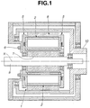
- the electric rotating machine includes inner rotor 7, outer rotor 8 and stator 1 disposed between inner and outer rotors 7 and 8.
- Inner rotor 7 is mounted to inner rotor shaft 9, and outer rotor 8 is mounted to outer rotor shaft 10.
- Inner and outer rotor shafts 9 and 10 have center axes aligned with center axis X of the electric rotating machine.
- Stator 1 and inner and outer rotors 7 and 8 are coaxially arranged and superimposed in a radial direction.
- the electric rotating machine has a three-layered structure.
- Each of inner rotor 7 and outer rotor 8 are formed by a permanent magnet.
- Inner and outer rotors 7 and 8 are different in number of N-S pole pairs.
- outer rotor 8 has the number of N-S pole pairs which is twice that of inner rotor 7.
- N poles and S poles are circumferentially alternately arranged.
- Stator 1 includes stator core 2 and axially opposed brackets 5 between which stator core 2 is interposed in contact with brackets 5.
- Stator core 2 is fixed to brackets 5 using bolts 6 which extend through stator core 2 and brackets 5.
- Stator core 2 is secured to brackets 5 by the friction force generated between the mutual contact surfaces of stator core 2 and brackets 5.
- Coil 28 is wound on stator core 2, to which compound current is applied.
- the compound current is composed of an alternating current generating a rotating magnetic field for the inner rotor and an alternating current generating a rotating magnetic field for the outer rotor.
- Inner rotor 7 and outer rotor 8 are independently driven by applying the compound current to coil 28 of stator core 2.
- stator core 2 has a generally ring-shape and includes a plurality of stator pieces 20 circumferentially arranged. Stator pieces 20 have a same shape and are formed by steel plates laminated in axial alignment with each other. As shown in Fig. 3 , each of stator pieces 20 includes body portion 29 on which coil 28 is wound, inner yoke 26 and outer yoke 27 which are disposed on a radial inside and a radial outside of body portion 29 and connected with each other by body portion 29. Inner yoke 26 is located on the side of inner rotor 7, and outer yoke 27 is located on the side of outer rotor 8.
- Coil area 21 is defined between inner and outer yokes 26 and 27 and body portion 29, in which coil 28 is disposed.
- Stator pieces 20 adjacent to one another define first air gap 30 circumferentially formed between outer yokes 27, second air gap 22 circumferentially formed between inner yokes 26, and mutual contact portions 23 circumferentially contacted at inner yokes 26.
- outer yoke 27 circumferentially projects and cooperates with body portion 29 to form a generally T-shape.
- First air gap 30 is formed by opposed outer yokes 27 of adjacent stator pieces 20.
- Inner yoke 26 circumferentially extends and has two radial recesses radially outward recessed from an inner peripheral edge thereof.
- the radial recesses are circumferentially spaced from each other to define radially inward extending projection 25 therebetween.
- projection 25 is a circumferentially intermediate portion between the radial recesses.
- Each of radial recesses cooperates with a radial recess of inner yoke 26 of adjacent stator piece 20 to form second air gap 22.
- Inner yoke 26 has contact portions 23 on circumferential opposite side peripheries thereof. Each of contact portions 23 is in contact with contact portion 23 of inner yoke 26 of adjacent stator piece 20.
- Contact portion 23 includes two contact regions which are disposed on the side of inner rotor 7 and on the side of coil area 21, respectively.
- Bolt hole 24 is disposed between the contact regions of contact portions 23 mutually contacted between inner yokes 26 of adjacent stator pieces 20. Namely, a half of bolt hole 24 is formed on each of the circumferential opposite side peripheries of inner yoke 26. Bolt 6 inserted into bolt hole 24 makes no clearance between an outer periphery thereof and a hole surrounding portion of inner yoke 26 which defines bolt hole 24.
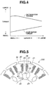
- second air gap 22 has radial length C
- projection 25 has radial length A.
- Characteristics of torques acting on inner rotor 7 and outer rotor 8, respectively, are determined by a ratio of radial length C to radial length A.
- Fig. 4 shows a relationship between radial length C and the torque acting on inner rotor 7 (hereinafter referred to as inner rotor torque) and the torque acting on outer rotor 8 (hereinafter referred to as outer rotor torque). As shown in Fig. 4 , if radial length C increases under condition that radial length A is kept constant, the inner rotor torque will increase and the outer rotor torque will decrease.
- the magnetic resistance between inner peripheral portions of adjacent inner yokes 26, namely, the magnetic resistance thereof on the side of inner rotor 7, increases so that flux leakage of stator core 2 relative to inner rotor 7 decreases.
- This allows efficient interlinkage of the magnetic flux of inner rotor 7 with that of stator core 2, increasing the inner rotor torque.
- the flux linkage between outer rotor 8 and stator core 2 decreases so that the outer rotor torque decreases.
- radial length C decreases under the same condition, the outer rotor torque will increase and the inner rotor torque will decrease.
- the inner rotor torque and the outer rotor torque namely, the magnetic resistance of stator core 2 on the side of each of inner and outer rotors 7 and 8, can be varied and set to desired values by changing the ratio of radial length C to radial length A.
- second air gap 22 has circumferential length B
- body portion 29 has circumferential length D
- projection 25 has circumferential length E.
- characteristics of the inner rotor torque and the outer rotor torque are determined depending on effective sectional area of stator core 2.
- the effective sectional area is determined based on a smallest circumferential length of stator piece 20.
- Circumferential length D of body portion 29 is set as the smallest circumferential length of stator piece 20.
- Circumferential length B is determined such that circumferential length E is not less than circumferential length D. If circumferential length E increases under condition that a sum of circumferential length B and circumferential length E is kept constant, the inner rotor torque will decrease and the outer rotor torque will increase.
- circumferential length B is determined such that circumferential length E is smaller than circumferential length D
- the effective sectional area of stator core 2 is determined based on circumferential length E. In this case, even if circumferential length D more increases, the magnetic flux interlinkable with stator core 2 will not increase.
- stator core 2 on the side of inner rotor 7 and the magnetic resistance thereof on the side of outer rotor 8 can be desirably controlled by adequately selecting the positions of second air gap 22 and contact portion 23 of stator core 2 as well as radial lengths C and A thereof. This can reduce flux leakage of stator core 2 relative to inner rotor 7, allowing a main magnetic flux of outer rotor 8 to pass through stator core 2. Further, since adjacent stator pieces 20 are in contact with one another at contact portions 23 thereof, stator core 2 can be enhanced in rigidity in the circumferential direction as compared with the stator core of the related art in which the stator pieces are spaced from one another.
- second air gap 22 is disposed on the radial inside of adjacent stator pieces 20, namely, on the side of inner rotor 7, and contact portion 23 is disposed on the radial outside thereof, namely, on the side of outer rotor 8.
- stator core 2 can be increased in rigidity.
- reduction of the magnetic flux interlinkable with stator core 2 can be prevented by setting radial length B of second air gap 22 based on the above-described relationship between circumferential length D of body portion 29 and circumferential length E of projection 25.
- second air gap 22 formed by adjacent stator pieces 20 of stator core 200 is located at a radially middle position of contact portion 23 of inner yoke 26.
- Contact portion 23 includes two contact regions which are disposed on the side of inner rotor 7 and on the side of outer rotor 8, respectively.
- Second air gap 22 is disposed between the contact regions of contact portion 23.
- Second air gap 22 is defined by a generally rectangular opening.
- Bolt hole 24 is arranged in an overlapped relation to second air gap 22.
- a bolt may be made of non-magnetic material when there exists no clearance between an outer periphery of the bolt and a periphery of bolt hole 24.
- the bolt made of non-magnetic material exerts no influence on the effect of second air gap 22.
- the bolt may be disposed in bolt hole 24 with a clearance between the outer periphery of the bolt and the periphery of bolt hole 24.
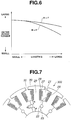
- second air gap 22 has radial length G. Radial length F extends between an inner peripheral edge of inner yoke 26 and an inner end of second air gap 22.
- Radial length H extends between an outer end of second air gap 22 and an outer peripheral edge of inner yoke 26 which defines coil area 21.
- radial length F is a length of the radial inside contact region of contact portion 23
- radial length H is a length of the radial outside contact region of contact portion 23.
- the inner rotor torque and the outer rotor torque can be controlled by adjusting radial length F, radial length G and radial length H. If radial length G of second air gap 22 increases, the inner rotor torque will increase and the outer rotor torque will decrease.
- Fig. 6 shows a relationship between these parameters F, G and H and the outer rotor torque. Further, a variation of the outer rotor torque relative to radial length G can be controlled by adjusting a ratio between radial length F and radial length H. If radial length F is smaller than radial length H, rate of reduction in the outer rotor torque will be lessened even when radial length G increases, as compared with a case where radial length F is larger than radial length H.
- the circumferential length extending between adjacent second air gaps 22 and the circumferential length extending between adjacent bolt holes 24 are not less than the circumferential length of body portion 29.
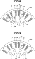
- FIG. 7 shows a stator core that is not part of the present invention, which differs in shape of the opening defining second air gap 22 from the second embodiment.
- each of stator pieces 20 of stator core 300 includes second air gap 22 defined by a circular opening.
- a circumferential length of an intermediate portion between adjacent second air gaps 22 is not less than the circumferential length of body portion 29.
- a bolt made of non-magnetic material is inserted into second air gap 22, and therefore, no separate bolt hole may be formed. This serves for reduction in dimension of stator core 300.
- stator cores 200 and 300 and stator 1 as a whole can be enhanced in rigidity. In these embodiments, the same effects as described in the first embodiment can be obtained.
- stator pieces 20 of stator core 400 have inner air gap 22A and outer air gap 22B which are radially spaced from each other.
- Inner air gap 22A and outer air gap 22B are disposed in an inner periphery of inner yoke 26 and an outer periphery thereof, respectively.
- Inner air gap 22A is formed on the side of inner rotor 7
- outer air gap 22B is formed on the side of coil area 21, namely, on the side of outer rotor 8.
- Inner air gap 22A is defined by a radial inner recess radially outward recessed from the inner peripheral edge of inner yoke 26.
- a radially inward extending projection is formed between adjacent inner air gaps 22A.
- Outer air gap 22B is defined by a radial outer recess radially inward recessed from the outer peripheral edge of inner yoke 26.
- a radially outward extending projection is formed between adjacent outer air gaps 22B.
- Contact portion 23 extends between inner air gap 22A and outer air gap 22B and in contact with contact portion 23 of inner yoke 26 of adjacent stator piece 20.
- Bolt hole 24 is located in a middle position of adjacent contact portions 23 mutually contacted with each other.
- the inner rotor torque and the outer rotor torque are controlled by adjusting radial length J of inner air gap 22A, radial length K of contact portion 23, and radial length L of outer air gap 22B.
- Circumferential lengths of inner and outer air gaps 22A and 22B may be set different from each other under condition that a circumferential length of the radially inward projection and a circumferential length of the radially outward projection are not less than the circumferential length of body portion 29. If radial length J of inner air gap 22A increases, the inner rotor torque will increase.
- the outer rotor torque is varied depending on radial length K of contact portion 23.
- a Bolt made of magnetic material may be inserted into bolt hole 24 to thereby magnetically connect adjacent stator pieces 20. In this case, main magnetic flux of outer rotor 8 can pass through the bolt, and therefore, a dimension of stator core 400 can be reduced.
- stator core 400 With the construction of stator core 400, the flux leakage relative to inner rotor 7 can be prevented by inner air gap 22A, and the flux leakage of coil 28 can be prevented by outer air gap 22B. Main magnetic flux of outer rotor 8 can pass through contact portion 23. The inner rotor torque and the outer rotor torque can be set to desired values, and the flux leakage relative to inner and outer rotors 7 and 8 can be suppressed. Further, stator core 400 can be enhanced in rigidity.
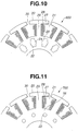
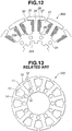
- stator cores 500, 600, 700 and 800 are formed by laminated steel plates.
- Each of the steel plates is an integral plate body formed by connecting together stator pieces 20 of each of stator cores 2, 200, 300 and 400 shown in the previous figures via contact portions 23.
- each of stator cores 500, 600, 700 and 800 as a whole can be improved in rigidity in the circumferential direction.
Landscapes
- Engineering & Computer Science (AREA)
- Power Engineering (AREA)
- Iron Core Of Rotating Electric Machines (AREA)
Claims (9)
- Eine Elektro-Rotations-Maschine, die umfasst:einen Innen-Rotor (7), der eine Mehrzahl von Permanent-Magneten beinhaltet, die umfänglich angeordnet sind;einen Außen-Rotor (8), der eine Mehrzahl von Permanent-Magneten beinhaltet, die umfänglich angeordnet sind, der Innen-Rotor (7) und der Außen-Rotor (8) sind koaxial positioniert und durch einen Verbund-Strom angetrieben; undeinen Stator (1), der zwischen dem Innen-Rotor (7) und dem Außen-Rotor (8) positioniert ist, der Stator (1) beinhaltet einen Stator-Kern (2, 200, 300, 400) und eine Spule (28) auf die der Verbund-Strom aufgebracht ist, der Stator-Kern (2, 200, 300, 400) beinhaltet eine Mehrzahl von umfänglich angeordneten Stator-Stücken (20), an jedem derselben ist die Spule (28) gewickelt, die Stator-Stücke (20) haben die gleiche Form und sind durch Platten ausgebildet, die in axialer Ausrichtung zueinander laminiert sind, jedes der Stator-Stücke (20) beinhaltet ein Innen-Joch (26), das radial innerhalb positioniert ist, ein Außen-Joch (27), das radial außen positioniert ist, und einen Spulen-Bereich (21), der zwischen den Innen- und Außen-Jochen (26, 27) definiert ist, in dem die Spule (28) positioniert ist, die Stator-Stücke (20), die benachbart zueinander sind, beinhalten einen ersten Luft-Spalt (30), der umfänglich zwischen den benachbarten Außen-Jochen (27) derselben ausgebildet ist, einen zweiten Luft-Spalt (22, 22A, 22B), der umfänglich zwischen den benachbarten Innen-Jochen (26) derselben ausgebildet ist, und gegenseitige Kontakt-Abschnitte (23), die umfänglich an den Innen-Jochen (26) derselben kontaktieren, wodurch jeder von den Kontakt-Abschnitten (23) zwei Kontakt-Bereiche umfasst, die jeweils an der Seite von dem Innen-Rotor (7) und der Seite von dem Außen-Rotor (8) positioniert sind, undeinen Bolzen (6), der die Stator-Stücke (20) verbindet, der Bolzen (6) erstreckt sich in ein Bolzen-Loch (24), das in den Kontakt-Abschnitten (23) ausgebildet ist, dadurch gekennzeichnet, dass das Bolzen-Loch (24) zwischen zwei Kontakt-Bereichen positioniert ist.
- Eine Elektro-Rotations-Maschine gemäß Anspruch 1, dadurch gekennzeichnet, dass einer von den zwei Kontakt-Bereichen der Kontakt-Abschnitte (23) radial außen von dem zweiten Luft-Spalt (22, 22A) angeordnet ist.
- Eine Elektro-Rotations-Maschine gemäß Anspruch 2, dadurch gekennzeichnet, dass jedes von den Stator-Stücken (20) einen Körper-Abschnitt (29) umfasst, der die Innen- und Außen-Joche (26, 27) verbindet, und die Spule (28), die darauf gewickelt ist, hält, und einen Zwischen-Abschnitt (25), der zwischen den zweiten Luft-Spalten (22, 22A, 22B) von benachbarten Innen-Jochen (26) positioniert ist, der Zwischen-Abschnitt (25) hat eine Umfangs-Länge (E) nicht weniger als eine Umfangs-Länge (D) des Körper-Abschnitts (29).
- Eine Elektro-Rotations-Maschine gemäß Anspruch 3, dadurch gekennzeichnet, dass der zweite Luft-Spalt (22) durch eine Radial-Ausnehmung, die an einem Innen-Umfang des Innen-Jochs (26) ausgebildet ist, definiert ist, der Zwischen-Abschnitt (25) ist ein Vorsprung, der zwischen benachbarten zwei radialen Ausnehmungen ausgebildet ist.
- Eine Elektro-Rotations-Maschine gemäß zumindest einem von den Ansprüchen 1 bis 4, gekennzeichnet durch den Bolzen (6), der aus nicht-magnetischem Material gemacht ist.
- Eine Elektro-Rotations-Maschine gemäß zumindest einem von den Ansprüchen 1 bis 5, dadurch gekennzeichnet, dass der zweite Luft-Spalt (22) durch eine Öffnung definiert ist, die eine Kreis-Form hat.
- Eine Elektro-Rotations-Maschine gemäß zumindest einem von den Ansprüchen 1 bis 6, dadurch gekennzeichnet, dass der zweite Luft-Spalt einen Innen-Luft-Spalt (22A) und einen Außen-Luft-Spalt (22B), der radial von dem Innen-Luft-Spalt (22A) beabstandet ist, umfasst, die Innen- und Außen-Luft-Spalte (22A, 22B) sind jeweils an der Seite des Innen-Rotors (7) und an der Seite des Außen-Rotors (8) positioniert, der Kontakt-Abschnitt (23) ist zwischen dem Innen- und Außen-Luft-Spalten (22A, 22B) positioniert.
- Eine Elektro-Rotations-Maschine gemäß Anspruch 7, gekennzeichnet durch zwei Zwischen-Abschnitte, die jeweils zwischen den benachbarten Innen-Luft-Spalten (22A) und zwischen den benachbarten Außen-Luft-Spalten (22B) positioniert sind, jeder von den zwei Zwischen-Abschnitten hat eine Umfangs-Länge nicht weniger als eine Umfangs-Länge von dem Körper-Abschnitt (29).
- Eine Elektro-Rotations-Maschine gemäß Anspruch 7 oder 8, dadurch gekennzeichnet, dass der Innen-Luft-Spalt (22A) und der Außen-Luft-Spalt (22B) jeweils durch eine Radial-Innen-Ausnehmung, die an einem Innen-Umfang des Innen-Jochs (26) ausgebildet sind, und einer Radial-Außen-Ausnehmung, die an einem Außen-Umfang derselben ausgebildet ist, definiert, die zwei Zwischen-Abschnitte sind Vorsprünge, die jeweils zwischen den benachbarten Radial-Innen-Ausnehmungen und zwischen den benachbarten Radial-Außen-Ausnehmungen ausgebildet sind.
Applications Claiming Priority (3)
| Application Number | Priority Date | Filing Date | Title |
|---|---|---|---|
| JP2002098633A JP3716808B2 (ja) | 2002-04-01 | 2002-04-01 | 回転電機 |
| JP2002098633 | 2002-04-01 | ||
| PCT/JP2003/003920 WO2003084033A1 (en) | 2002-04-01 | 2003-03-28 | Electric machine with inner and outer rotor |
Publications (2)
| Publication Number | Publication Date |
|---|---|
| EP1490950A1 EP1490950A1 (de) | 2004-12-29 |
| EP1490950B1 true EP1490950B1 (de) | 2019-05-22 |
Family
ID=28671954
Family Applications (1)
| Application Number | Title | Priority Date | Filing Date |
|---|---|---|---|
| EP03715561.1A Expired - Lifetime EP1490950B1 (de) | 2002-04-01 | 2003-03-28 | Elektrische maschine mit innen- und aussenrotor |
Country Status (5)
| Country | Link |
|---|---|
| US (1) | US6952069B2 (de) |
| EP (1) | EP1490950B1 (de) |
| JP (1) | JP3716808B2 (de) |
| CN (1) | CN100426635C (de) |
| WO (1) | WO2003084033A1 (de) |
Families Citing this family (24)
| Publication number | Priority date | Publication date | Assignee | Title |
|---|---|---|---|---|
| US7409434B2 (en) * | 2001-09-07 | 2008-08-05 | Xerox Corporation | Method and apparatus for controlling document service requests using a mobile computing device |
| US7129614B2 (en) * | 2002-09-20 | 2006-10-31 | Robert Bosch Gmbh | Strip-shaped lamina and laminated stator core for an electric machine |
| KR100569502B1 (ko) * | 2003-12-05 | 2006-04-07 | 주식회사 대우일렉트로닉스 | 2중 배면 권선 구조를 가진 모터 스테이터 |
| JP4706215B2 (ja) * | 2004-09-21 | 2011-06-22 | 日産自動車株式会社 | 複軸多層型回転電機のステータ構造 |
| JP4849071B2 (ja) * | 2005-10-13 | 2011-12-28 | パナソニック株式会社 | 2つのロータを有するモータ |
| US7825548B2 (en) * | 2005-10-21 | 2010-11-02 | Kabushiki Kaisha Yaskawa Denki | Cylindrical linear motor |
| CN101051781B (zh) * | 2006-03-16 | 2011-01-19 | 日产自动车株式会社 | 电动机/发电机 |
| DE102008000244A1 (de) | 2008-02-06 | 2009-08-13 | Robert Bosch Gmbh | Kern für einen Elektromotor und einen Elektromotor mit einem solchen Kern |
| JP5465866B2 (ja) * | 2008-11-10 | 2014-04-09 | トヨタ自動車株式会社 | ステータコアおよび回転電機 |
| JP5736771B2 (ja) * | 2010-12-27 | 2015-06-17 | 株式会社明電舎 | 回転電機の固定子 |
| WO2013118319A1 (ja) * | 2012-02-08 | 2013-08-15 | 日本精工株式会社 | アクチュエータ、ステータ、モータ、回転直動変換機構及びリニアアクチュエータ |
| GB2503500A (en) | 2012-06-29 | 2014-01-01 | Nidec Motors & Actuators Gmbh Germany | An armature connecting wire arrangment for an electric motor |
| GB2507072B (en) * | 2012-10-17 | 2015-06-10 | Protean Electric Ltd | A stator or rotor |
| EP2940841B1 (de) * | 2012-12-28 | 2018-04-11 | IHI Corporation | Geschaltete reluktanzdrehmaschine mit doppelstator |
| WO2014109218A1 (ja) | 2013-01-10 | 2014-07-17 | 株式会社Ihi | ダブルステータ型スイッチトリラクタンス回転機 |
| EP3076529A1 (de) * | 2015-04-01 | 2016-10-05 | Siemens Aktiengesellschaft | Elektrische rotierende maschine mit lateral magnetisierten linsenförmigen magneten |
| CN107040117B (zh) * | 2016-02-04 | 2020-07-07 | 同济大学 | 直线压缩机的定子、直线电机及直线压缩机 |
| JP6733568B2 (ja) * | 2017-02-02 | 2020-08-05 | トヨタ自動車株式会社 | 回転電機 |
| CN107919746B (zh) * | 2017-12-21 | 2020-12-29 | 深圳市雅康诚科技发展有限公司 | 定子和直驱转台 |
| CN108545679A (zh) * | 2018-06-26 | 2018-09-18 | 珠海市蓝海工业技术有限公司 | 一种锅炉检修平台 |
| CN109742917B (zh) * | 2019-02-28 | 2024-07-16 | 郑州大学 | 一种双转子永磁同步电机转子固定结构 |
| US11923733B2 (en) * | 2020-08-28 | 2024-03-05 | Quantentech Limited | High efficiency high density motor and generator with multiple airgaps |
| DE102021106186A1 (de) * | 2021-03-15 | 2022-09-15 | Ebm-Papst Mulfingen Gmbh & Co. Kg | Modular aufgebautes, segmentiertes Statorpaket |
| CN113489179A (zh) * | 2021-07-20 | 2021-10-08 | 广东威灵电机制造有限公司 | 电机、电动自行车和家电设备 |
Family Cites Families (8)
| Publication number | Priority date | Publication date | Assignee | Title |
|---|---|---|---|---|
| JPS5441401A (en) * | 1977-09-07 | 1979-04-02 | Hitachi Ltd | Stator core in motor |
| JP3568364B2 (ja) * | 1996-09-30 | 2004-09-22 | 松下電器産業株式会社 | 回転電機のコア |
| JP3480315B2 (ja) | 1998-06-10 | 2003-12-15 | 日産自動車株式会社 | 回転電機 |
| JP2001025185A (ja) | 1999-07-06 | 2001-01-26 | Toshiba Corp | モータ |
| JP3496595B2 (ja) | 1999-10-27 | 2004-02-16 | 日産自動車株式会社 | 回転電機 |
| EP1164688B1 (de) | 2000-06-14 | 2007-07-18 | Nissan Motor Company, Limited | Rotierende elektrische Maschine mit Statorstützstruktur |
| JP3671816B2 (ja) | 2000-06-14 | 2005-07-13 | 日産自動車株式会社 | 回転電機のステータ支持構造 |
| EP1191673A3 (de) * | 2000-09-14 | 2002-08-21 | Denso Corporation | Kompakter und zuverlässiger Aufbau einer Synchronmaschine mit mehreren Läufern |
-
2002
- 2002-04-01 JP JP2002098633A patent/JP3716808B2/ja not_active Expired - Fee Related
-
2003
- 2003-03-28 WO PCT/JP2003/003920 patent/WO2003084033A1/en not_active Ceased
- 2003-03-28 CN CNB038003880A patent/CN100426635C/zh not_active Expired - Fee Related
- 2003-03-28 EP EP03715561.1A patent/EP1490950B1/de not_active Expired - Lifetime
- 2003-03-28 US US10/476,062 patent/US6952069B2/en not_active Expired - Lifetime
Non-Patent Citations (1)
| Title |
|---|
| None * |
Also Published As
| Publication number | Publication date |
|---|---|
| US6952069B2 (en) | 2005-10-04 |
| EP1490950A1 (de) | 2004-12-29 |
| JP3716808B2 (ja) | 2005-11-16 |
| CN1515063A (zh) | 2004-07-21 |
| JP2003299329A (ja) | 2003-10-17 |
| CN100426635C (zh) | 2008-10-15 |
| US20040130229A1 (en) | 2004-07-08 |
| WO2003084033A1 (en) | 2003-10-09 |
Similar Documents
| Publication | Publication Date | Title |
|---|---|---|
| US6952069B2 (en) | Electric machine with inner and outer rotor | |
| EP0598137B1 (de) | Rotor für synchronmotor | |
| JP3282521B2 (ja) | リラクタンスモータ | |
| US6008559A (en) | Motor using a rotor including an interior permanent magnet | |
| US8405270B2 (en) | Permanent magnet buried type electric motor | |
| JP3454234B2 (ja) | 分割コアモータ | |
| US7187098B2 (en) | Axial gap rotating electrical machine | |
| JP4904736B2 (ja) | 回転電機の固定子 | |
| US6624545B1 (en) | Electric rotating machine and manufacturing method thereof | |
| US6927519B2 (en) | Rotor assembly for an electrical machine and permanent magnet motor comprising such a rotor assembly | |
| CN113615042B (zh) | 旋转电机 | |
| US7923887B2 (en) | Brushless motor | |
| US10348144B2 (en) | Permanent-magnet-embedded motor | |
| AU2005242216B2 (en) | Motor | |
| JP2008193809A (ja) | 埋込磁石型モータ | |
| WO2017195498A1 (ja) | 回転子および回転電機 | |
| JPH0736459Y2 (ja) | 永久磁石界磁形回転子 | |
| JP2005269831A (ja) | ブラシレスdcモータ | |
| JP7183487B1 (ja) | 同期リラクタンスモータの回転子 | |
| US12294243B2 (en) | Rotating electric machine | |
| JP7172979B2 (ja) | 回転電機 | |
| JP7308163B2 (ja) | モータ | |
| US20250088050A1 (en) | Rotating electric machine | |
| JP7773357B2 (ja) | モータ | |
| JP2006254651A (ja) | 回転電機 |
Legal Events
| Date | Code | Title | Description |
|---|---|---|---|
| PUAI | Public reference made under article 153(3) epc to a published international application that has entered the european phase |
Free format text: ORIGINAL CODE: 0009012 |
|
| 17P | Request for examination filed |
Effective date: 20031113 |
|
| AK | Designated contracting states |
Kind code of ref document: A1 Designated state(s): AT BE BG CH CY CZ DE DK EE ES FI FR GB GR HU IE IT LI LU MC NL PT RO SE SI SK TR |
|
| 17Q | First examination report despatched |
Effective date: 20100205 |
|
| GRAP | Despatch of communication of intention to grant a patent |
Free format text: ORIGINAL CODE: EPIDOSNIGR1 |
|
| RBV | Designated contracting states (corrected) |
Designated state(s): DE FR GB |
|
| INTG | Intention to grant announced |
Effective date: 20190131 |
|
| GRAS | Grant fee paid |
Free format text: ORIGINAL CODE: EPIDOSNIGR3 |
|
| GRAA | (expected) grant |
Free format text: ORIGINAL CODE: 0009210 |
|
| AK | Designated contracting states |
Kind code of ref document: B1 Designated state(s): DE FR GB |
|
| REG | Reference to a national code |
Ref country code: GB Ref legal event code: FG4D |
|
| REG | Reference to a national code |
Ref country code: DE Ref legal event code: R096 Ref document number: 60352035 Country of ref document: DE |
|
| REG | Reference to a national code |
Ref country code: DE Ref legal event code: R097 Ref document number: 60352035 Country of ref document: DE |
|
| PLBE | No opposition filed within time limit |
Free format text: ORIGINAL CODE: 0009261 |
|
| STAA | Information on the status of an ep patent application or granted ep patent |
Free format text: STATUS: NO OPPOSITION FILED WITHIN TIME LIMIT |
|
| 26N | No opposition filed |
Effective date: 20200225 |
|
| PGFP | Annual fee paid to national office [announced via postgrant information from national office to epo] |
Ref country code: GB Payment date: 20200318 Year of fee payment: 18 Ref country code: DE Payment date: 20200317 Year of fee payment: 18 |
|
| PGFP | Annual fee paid to national office [announced via postgrant information from national office to epo] |
Ref country code: FR Payment date: 20200214 Year of fee payment: 18 |
|
| REG | Reference to a national code |
Ref country code: DE Ref legal event code: R119 Ref document number: 60352035 Country of ref document: DE |
|
| GBPC | Gb: european patent ceased through non-payment of renewal fee |
Effective date: 20210328 |
|
| PG25 | Lapsed in a contracting state [announced via postgrant information from national office to epo] |
Ref country code: FR Free format text: LAPSE BECAUSE OF NON-PAYMENT OF DUE FEES Effective date: 20210331 Ref country code: GB Free format text: LAPSE BECAUSE OF NON-PAYMENT OF DUE FEES Effective date: 20210328 Ref country code: DE Free format text: LAPSE BECAUSE OF NON-PAYMENT OF DUE FEES Effective date: 20211001 |