EP1490984B1 - System und verfahren zum übertragen eines signals in einem mobilkommunikationssystem - Google Patents
System und verfahren zum übertragen eines signals in einem mobilkommunikationssystem Download PDFInfo
- Publication number
- EP1490984B1 EP1490984B1 EP03745025A EP03745025A EP1490984B1 EP 1490984 B1 EP1490984 B1 EP 1490984B1 EP 03745025 A EP03745025 A EP 03745025A EP 03745025 A EP03745025 A EP 03745025A EP 1490984 B1 EP1490984 B1 EP 1490984B1
- Authority
- EP
- European Patent Office
- Prior art keywords
- symbol
- transmit
- vector
- antennas
- beamforming
- Prior art date
- Legal status (The legal status is an assumption and is not a legal conclusion. Google has not performed a legal analysis and makes no representation as to the accuracy of the status listed.)
- Expired - Lifetime
Links
- 238000000034 method Methods 0.000 title claims abstract description 50
- 238000010295 mobile communication Methods 0.000 title claims abstract description 36
- 230000008054 signal transmission Effects 0.000 claims abstract description 40
- 239000013598 vector Substances 0.000 claims description 112
- 239000011159 matrix material Substances 0.000 claims description 54
- 238000000354 decomposition reaction Methods 0.000 claims description 22
- 238000001514 detection method Methods 0.000 abstract description 2
- 238000010276 construction Methods 0.000 description 11
- 230000005540 biological transmission Effects 0.000 description 10
- 238000012545 processing Methods 0.000 description 6
- 230000000875 corresponding effect Effects 0.000 description 5
- 230000002708 enhancing effect Effects 0.000 description 3
- 230000001419 dependent effect Effects 0.000 description 2
- 238000011161 development Methods 0.000 description 2
- 239000000654 additive Substances 0.000 description 1
- 230000000996 additive effect Effects 0.000 description 1
- 230000015556 catabolic process Effects 0.000 description 1
- 238000004891 communication Methods 0.000 description 1
- 230000002596 correlated effect Effects 0.000 description 1
- 238000006731 degradation reaction Methods 0.000 description 1
- 238000012986 modification Methods 0.000 description 1
- 230000004048 modification Effects 0.000 description 1
- 238000003672 processing method Methods 0.000 description 1
Images





Classifications
-
- H—ELECTRICITY
- H04—ELECTRIC COMMUNICATION TECHNIQUE
- H04B—TRANSMISSION
- H04B7/00—Radio transmission systems, i.e. using radiation field
- H04B7/02—Diversity systems; Multi-antenna system, i.e. transmission or reception using multiple antennas
- H04B7/04—Diversity systems; Multi-antenna system, i.e. transmission or reception using multiple antennas using two or more spaced independent antennas
- H04B7/0413—MIMO systems
- H04B7/0417—Feedback systems
-
- H—ELECTRICITY
- H04—ELECTRIC COMMUNICATION TECHNIQUE
- H04B—TRANSMISSION
- H04B7/00—Radio transmission systems, i.e. using radiation field
- H04B7/02—Diversity systems; Multi-antenna system, i.e. transmission or reception using multiple antennas
-
- H—ELECTRICITY
- H04—ELECTRIC COMMUNICATION TECHNIQUE
- H04B—TRANSMISSION
- H04B7/00—Radio transmission systems, i.e. using radiation field
- H04B7/02—Diversity systems; Multi-antenna system, i.e. transmission or reception using multiple antennas
- H04B7/04—Diversity systems; Multi-antenna system, i.e. transmission or reception using multiple antennas using two or more spaced independent antennas
- H04B7/0408—Diversity systems; Multi-antenna system, i.e. transmission or reception using multiple antennas using two or more spaced independent antennas using two or more beams, i.e. beam diversity
-
- H—ELECTRICITY
- H04—ELECTRIC COMMUNICATION TECHNIQUE
- H04B—TRANSMISSION
- H04B7/00—Radio transmission systems, i.e. using radiation field
- H04B7/02—Diversity systems; Multi-antenna system, i.e. transmission or reception using multiple antennas
- H04B7/04—Diversity systems; Multi-antenna system, i.e. transmission or reception using multiple antennas using two or more spaced independent antennas
- H04B7/06—Diversity systems; Multi-antenna system, i.e. transmission or reception using multiple antennas using two or more spaced independent antennas at the transmitting station
- H04B7/0613—Diversity systems; Multi-antenna system, i.e. transmission or reception using multiple antennas using two or more spaced independent antennas at the transmitting station using simultaneous transmission
- H04B7/0615—Diversity systems; Multi-antenna system, i.e. transmission or reception using multiple antennas using two or more spaced independent antennas at the transmitting station using simultaneous transmission of weighted versions of same signal
-
- H—ELECTRICITY
- H04—ELECTRIC COMMUNICATION TECHNIQUE
- H04B—TRANSMISSION
- H04B7/00—Radio transmission systems, i.e. using radiation field
- H04B7/02—Diversity systems; Multi-antenna system, i.e. transmission or reception using multiple antennas
- H04B7/04—Diversity systems; Multi-antenna system, i.e. transmission or reception using multiple antennas using two or more spaced independent antennas
- H04B7/06—Diversity systems; Multi-antenna system, i.e. transmission or reception using multiple antennas using two or more spaced independent antennas at the transmitting station
- H04B7/0613—Diversity systems; Multi-antenna system, i.e. transmission or reception using multiple antennas using two or more spaced independent antennas at the transmitting station using simultaneous transmission
- H04B7/0615—Diversity systems; Multi-antenna system, i.e. transmission or reception using multiple antennas using two or more spaced independent antennas at the transmitting station using simultaneous transmission of weighted versions of same signal
- H04B7/0619—Diversity systems; Multi-antenna system, i.e. transmission or reception using multiple antennas using two or more spaced independent antennas at the transmitting station using simultaneous transmission of weighted versions of same signal using feedback from receiving side
- H04B7/0621—Feedback content
- H04B7/0634—Antenna weights or vector/matrix coefficients
-
- H—ELECTRICITY
- H04—ELECTRIC COMMUNICATION TECHNIQUE
- H04L—TRANSMISSION OF DIGITAL INFORMATION, e.g. TELEGRAPHIC COMMUNICATION
- H04L25/00—Baseband systems
- H04L25/02—Details ; arrangements for supplying electrical power along data transmission lines
- H04L25/0202—Channel estimation
- H04L25/0204—Channel estimation of multiple channels
-
- H—ELECTRICITY
- H04—ELECTRIC COMMUNICATION TECHNIQUE
- H04L—TRANSMISSION OF DIGITAL INFORMATION, e.g. TELEGRAPHIC COMMUNICATION
- H04L25/00—Baseband systems
- H04L25/02—Details ; arrangements for supplying electrical power along data transmission lines
- H04L25/0202—Channel estimation
- H04L25/024—Channel estimation channel estimation algorithms
- H04L25/0242—Channel estimation channel estimation algorithms using matrix methods
- H04L25/0248—Eigen-space methods
-
- H—ELECTRICITY
- H04—ELECTRIC COMMUNICATION TECHNIQUE
- H04L—TRANSMISSION OF DIGITAL INFORMATION, e.g. TELEGRAPHIC COMMUNICATION
- H04L25/00—Baseband systems
- H04L25/02—Details ; arrangements for supplying electrical power along data transmission lines
- H04L25/03—Shaping networks in transmitter or receiver, e.g. adaptive shaping networks
- H04L25/03006—Arrangements for removing intersymbol interference
- H04L25/03343—Arrangements at the transmitter end
-
- H—ELECTRICITY
- H04—ELECTRIC COMMUNICATION TECHNIQUE
- H04B—TRANSMISSION
- H04B7/00—Radio transmission systems, i.e. using radiation field
- H04B7/02—Diversity systems; Multi-antenna system, i.e. transmission or reception using multiple antennas
- H04B7/04—Diversity systems; Multi-antenna system, i.e. transmission or reception using multiple antennas using two or more spaced independent antennas
- H04B7/06—Diversity systems; Multi-antenna system, i.e. transmission or reception using multiple antennas using two or more spaced independent antennas at the transmitting station
- H04B7/0613—Diversity systems; Multi-antenna system, i.e. transmission or reception using multiple antennas using two or more spaced independent antennas at the transmitting station using simultaneous transmission
- H04B7/0615—Diversity systems; Multi-antenna system, i.e. transmission or reception using multiple antennas using two or more spaced independent antennas at the transmitting station using simultaneous transmission of weighted versions of same signal
- H04B7/0617—Diversity systems; Multi-antenna system, i.e. transmission or reception using multiple antennas using two or more spaced independent antennas at the transmitting station using simultaneous transmission of weighted versions of same signal for beam forming
-
- H—ELECTRICITY
- H04—ELECTRIC COMMUNICATION TECHNIQUE
- H04B—TRANSMISSION
- H04B7/00—Radio transmission systems, i.e. using radiation field
- H04B7/02—Diversity systems; Multi-antenna system, i.e. transmission or reception using multiple antennas
- H04B7/04—Diversity systems; Multi-antenna system, i.e. transmission or reception using multiple antennas using two or more spaced independent antennas
- H04B7/08—Diversity systems; Multi-antenna system, i.e. transmission or reception using multiple antennas using two or more spaced independent antennas at the receiving station
- H04B7/0837—Diversity systems; Multi-antenna system, i.e. transmission or reception using multiple antennas using two or more spaced independent antennas at the receiving station using pre-detection combining
- H04B7/0842—Weighted combining
- H04B7/0848—Joint weighting
- H04B7/0854—Joint weighting using error minimizing algorithms, e.g. minimum mean squared error [MMSE], "cross-correlation" or matrix inversion
-
- H—ELECTRICITY
- H04—ELECTRIC COMMUNICATION TECHNIQUE
- H04L—TRANSMISSION OF DIGITAL INFORMATION, e.g. TELEGRAPHIC COMMUNICATION
- H04L25/00—Baseband systems
- H04L25/02—Details ; arrangements for supplying electrical power along data transmission lines
- H04L25/03—Shaping networks in transmitter or receiver, e.g. adaptive shaping networks
- H04L25/03006—Arrangements for removing intersymbol interference
- H04L2025/0335—Arrangements for removing intersymbol interference characterised by the type of transmission
- H04L2025/03426—Arrangements for removing intersymbol interference characterised by the type of transmission transmission using multiple-input and multiple-output channels
-
- H—ELECTRICITY
- H04—ELECTRIC COMMUNICATION TECHNIQUE
- H04L—TRANSMISSION OF DIGITAL INFORMATION, e.g. TELEGRAPHIC COMMUNICATION
- H04L25/00—Baseband systems
- H04L25/02—Details ; arrangements for supplying electrical power along data transmission lines
- H04L25/03—Shaping networks in transmitter or receiver, e.g. adaptive shaping networks
- H04L25/03006—Arrangements for removing intersymbol interference
- H04L2025/03777—Arrangements for removing intersymbol interference characterised by the signalling
- H04L2025/03802—Signalling on the reverse channel
-
- H—ELECTRICITY
- H04—ELECTRIC COMMUNICATION TECHNIQUE
- H04L—TRANSMISSION OF DIGITAL INFORMATION, e.g. TELEGRAPHIC COMMUNICATION
- H04L25/00—Baseband systems
- H04L25/02—Details ; arrangements for supplying electrical power along data transmission lines
- H04L25/0202—Channel estimation
- H04L25/0224—Channel estimation using sounding signals
- H04L25/0228—Channel estimation using sounding signals with direct estimation from sounding signals
Definitions
- the present invention relates to a mobile communication system and, more particularly, to a signal transmission method and system for a mobile communication system using multiple antennas.
- Figure 1 illustrates one example of a general mobile communication system adopting a MIMO system.
- a conventional MIMO system includes: a plurality of transmit antennas 12, a vector encoder 10 for transmitting sequentially generated transmit data (symbols) to each transmit antenna 12; a plurality of receive antennas 14; and a V-BLAST signal processor 16 for processing data received through the receive antennas 14 in a V-BLAST (Vertical-Bell Labs Layered Space Time Architecture) method, and estimating and demodulating a transmit data.
- V-BLAST Very-Bell Labs Layered Space Time Architecture
- the vector encoder 10 converts the sequentially generated transmit data in a serial-to-parallel method and transmits them to each transmit antenna 12.
- the V-BLAST METHOD is a sort of a transmission technique of a MIMO mobile communication system using multiple antennas, for which M number of transmit antennas 12 and N number of receive antennas 14 are used.
- Figure 1 shows the case of using 4 transmit antennas 12, but without being limited thereto, two or more antennas can be set arbitrarily.
- the vector encoder 10 Without performing a certain signal processing for enhancing a transmission quality on the transmit data, the vector encoder 10 simply processes the transmit data a1-a4 in parallel and transmits them to each antenna 12. Then, each transmit antenna 12 transmits each different transmit data in the air.
- V-BLAST signal processor 16 Data received through each receive antenna 14 is inputted to the V-BLAST signal processor 16, and the V-BLAST signal processor 16 performs a signal processing suitably, that is, in a V-BLAST method, and detects the transmit data a1-a4.
- V-BLAST signal processor 16 The operation of the V-BLAST signal processor 16 will now be described in detail.
- the V-BLAST signal processor 16 receives the reception signals from each receive antenna 14 of the receive antenna array and constructs a reception data vector (receive vector). Subsequently, the V-BLAST signal processor 16 detects a transmission signal by using the receive vector.
- V-BLAST signal processor 16 detects the transmit symbol a specific transmit antenna has transmitted, it regards transmit symbols other transmit antennas 12 have transmitted as an interference signal.
- the V-BLAST signal processor 16 calculates a weight vector of each receive antenna 14 for each symbol transmitted from each transmit antenna 12 and simultaneously subtracts the first detected symbol component from the receive vector, thereby estimating each symbol while minimizing influence of each symbol.
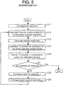
- Figure 2 is a flow chart of a method for estimating the transmit symbol by the V-BLAST signal processor 16.
- the V-BLAST signal processor 16 constructs the signals received through each receive antenna 14 as receive vectors (step S11).
- the channel matrix (H) can be expressed by N x M matrix.
- the channel matrix (H) is obtained through estimation by the V-BLAST signal processor 18.
- 'v' in equation (1) is a Gaussian noise, Since the noise is induced to each receive antenna 14, 'v' is N x 1 vector.
- the signals transmitted through the M number of transmit antennas 12 pass through a different communication channel (h i,j ), and the V-BLAST signal processor 16 receives the signals through the N number of receive antennas 14.
- the V-BLAST signal processor 16 calculates each weight vector of the signals, and estimates symbols transmitted from each transmit antenna 12 by using the calculated weight vector and the receive vector.
- the weight vector (wi) which should be inner-producted to a corresponding receive vector so as for the ith transmit antenna to detect a symbol transmitted from the antenna, has a property that it is '1' only when inner-producted to the ith column vector of the channel matrix (H) and '0' when inner-producted to the other remaining column vectors of the channel matrix (H).
- the transmit symbols are sequentially detected, and when the weight vector to be used for detecting a current symbol is obtained, since any influence of the previously detected symbols should be excluded, the expression 'j ⁇ l' is used in equation (2).
- the weight vector satisfying the quality of equation (2) can be obtained as follows:
- equation (3) expresses the receive vector with the received symbols as a shape of a linear sum.
- the V-BLAST signal processor 16 updates the weight vector for every transmit symbol to be detected and uses it.
- the V-BLAST signal processor 16 starts updating a weight vector in order to obtain a weight vector for each transmit symbol to be detected.
- the V-BLAST signal processor 16 obtains a moore-penrose pseudoinverse matrix (H + or G 1 ) for the estimated channel matrix (H) (step S13).
- G ⁇ 1 H +
- the V-BLAST signal processor 16 selects a row vector with the smallest vector norm value from row vectors of a G1 matrix, as a weight vector (step S15).
- the Kth line of the G1 matrix is selected as a weight vector (w K ) for detecting the Kth transmit symbol.
- the V-BLAST signal processor 16 inner-products the receive vector (r) and the weight vector (w K ) to estimate a symbol transmitted from the Kth transmit antenna (step S17).
- the receiving end that is, the V-BLAST signal processor 16 is well aware of a modulation method (i.e., QPSK, QAM, etc.) used in a sending end of the MIMO mobile communication system.
- a modulation method i.e., QPSK, QAM, etc.
- the V-BLAST signal processor 18 is able to recognize which constellation the estimated symbol belongs to, it determines the estimated symbol as a transmit symbol (ak) transmitted form the Kth transmit antenna.
- the V-BLAST signal processor 18 checks whether the M number of transmit symbols transmitted from the M number of transmit antennas 12 have been all detected (step S21). If there still remains transmit symbols to be detected, the V-BLAST signal processor 18 performs a procedure for updating the weight vector in order to detect the remaining transmit symbols.
- the V-BLAST signal processor 18 removes influence of the Kth symbol (a K H K ) from the receive vector (r) of equation (3) to obtain a receive vector (r 2 ) to be used for the second updating (step S23).
- r 2 r - a K ⁇ H K
- the V-BALST signal processor 18 estimates a channel matrix (H 2 ) to be used to obtain G 2 , that is, the second weight vector (step S25). Namely, the V-BLAST signal processor 16 deletes the column vector (Kth column) corresponding to the detected transmit symbol (a k ) from the previous channel matrix (H) and estimates a new channel matrix (H 2 ).
- the V-BLAST signal processor 18 selects a row vector with the smallest vector norm from row vectors of the G 2 matrix, as a weight vector (step S15). For instance, assumption that the selected row vector is the Vth row vector, the Vth line of the G 2 matrix is used as a weight vector (w V ) for detecting the Vth transmit symbol.
- the V-BLAST signal processor 16 inner-products the receive vector (r 2 ) and the weight vector (w V ) to estimate a symbol transmitted from the Vth transmit antenna (step S17).
- the V-BLAST signal processor 18 is already aware of the digital modulation method used in the sending end of the MIMO mobile communication system, it can judge which constellation the estimated symbol belongs to, based on which the V-BLAST signal processor detects a symbol (a V ) transmitted from the Vth transmit antenna. (step S19).
- the V-BLAST signal processor 18 checks whether the M number of transmit symbols transmitted from the M number of transmit antennas 12 have been all detected (step S21). If not all transmit symbols have been detected, the operations after the steps S23 and S25 are repeatedly performed. If all the transmit symbols have been detected, the steps are terminated.
- the transmit symbol is simply converted serial-to-parallel without being subjected to an additional signal processing, and then transmitted through the transmit antennas. Then, the receiving end sequentially detects the transmit data each transmit antenna has transmitted. At this time, the symbols transmitted independently from each transmit antenna should maintain their independence while passing through the mobile communication channel.
- an independent channel should be guaranteed between each transmit antenna and each receive antenna. But, in some cases, actually, independent channels as many as the transmit antennas are not guaranteed. Especially, in case of a system using only the independence between antennas, the greater the correlation between antennas, the more a signal gain is degraded. Thus, in such a case, a method of using the correlation of the antennas should be also considered.
- EP 1 187 363 A1 may be construed to disclose a signal transmission method for a multiple input multiple output, MIMO, mobile communication system using multiple transmit antennas in a transmitting end.
- the method may comprise the steps of demultiplexing sequentially inputted symbols, performing a beamforming on each symbol, the beam forming being performed by multiplying each symbol by a weight ( ⁇ 1 ), transmitting a beamformed signal containing each beamformed symbol through a plurality of transmit antennas, collecting the transmitted signals by a plurality of receive antennas, detecting a transmit symbol, estimating channel parameters from the collected signals, and feeding back the estimated channel parameters.
- an object of the present invention is to provide a signal transmission method and system for a mobile communication system using an independence and a correlation between antennas.
- Another object of the present invention is to provide a signal transmission method that is capable of enhancing a symbol detecting capability of a receiving end in a mobile communication system.
- Still another object of the present invention is to provide a signal transmission method in which beamforming is performed on each symbol and the beamformed symbol is assigned to a transmit antenna.
- the beamforming is performed by multiplying each symbol to be transmitted by a weight vector.
- the weight vector is an eigenvector feedback from a receiving end or a eigenvector calculated in a sending end.
- the signal transmission method of the present invention power of each symbol is adjusted by an eigenvalue.
- the eigenvalue is calculated in the sending end or feedback from the receiving end.
- a weight vector is an eigenvector.
- the signal transmission method for a mobile communication system includes the steps of: receiving an eigenvalue from the receiving end; and adjusting power of each symbol by using the received eigenvalue.
- the signal transmission method of the present invention includes: a step of adjusting power of each symbol by using the calculated eigenvalue.
- the signal transmission system for a mobile communication system of the present invention includes: a vector estimation unit for estimating a transmit vector from collected signals by using a certain method; and a symbol detector for performing a beamforming on the estimated transmit vector and detecting a transmit symbol.
- the certain method is a zero-forcing or a minimum mean square error (MMSE).
- MMSE minimum mean square error
- the signal transmission system for a mobile communication system of the present invention includes: a channel estimation unit for estimating a channel matrix from collected signals; and an eigen decomposition unit for eigen-decomposing the estimated channel matrix, calculating an eigenvector and an eigenvalue, and feeding them back to the sending end.
- the beamforming unit performs the beamforming by multiplying each symbol to be transmitted by a weight vector.
- the weight vector is an eigenvector fedback from the receiving end or an eigenvector calculated in the sending end.
- the beamforming unit adjusts power of each symbol by using the eigenvalue.
- the eigenvalue is calculated in the sending end or is fedback from the receiving end.
- each antenna is operated simply as an independent channel without considering the correlation between antennas. That is, in the case of using the system using the dependence between antennas, the greater the correlation between antennas, the more the gain is degraded. In such a case, the gain degradation caused due to the correlation between antennas can be effectively prevented by also employing a method using the correlation between antennas.
- the present invention proposes a method for enhancing a system performance by also considering the correlation as well as the independence between antennas.
- the present invention paying attention to the fact that the sending end is constructed with an antenna array, beamforming is performed on each symbol before transmitting each symbol.
- FIG. 3 illustrates the construction of the signal transmission apparatus for a mobile communication system in accordance with a first embodiment of the present invention.
- a signal transmission apparatus for a mobile communication system in accordance with the first embodiment of the present invention includes: a demultiplexer 20 for demultiplexing sequentially inputted symbols; a beamforming unit 22 for performing a beamforming on each demultiplexed symbol in consideration of a correlation between antennas; a plurality of transmit antennas 50 for transmitting the beamformed signals; a plurality of receive antennas 60 for collecting signals transmitted from the transmit antennas 60; a vector estimation unit 24 for estimating a transmit vector from the collected from the transmit antennas 50; and a symbol detector 26 for performing a beamforming on the estimated transmit vector and detecting transmission (Tx) symbols.
- a demultiplexer 20 for demultiplexing sequentially inputted symbols
- a beamforming unit 22 for performing a beamforming on each demultiplexed symbol in consideration of a correlation between antennas
- a plurality of transmit antennas 50 for transmitting the beamformed signals
- a plurality of receive antennas 60 for collecting signals transmitted from the transmit antennas 60
- the beamforming unit 22 performs the beamforming by multiplying each symbol by a weight vector
- the symbol detector 26 performs the beamforming by multiplying the estimated transmit vector by a conjugate value of the weight vector which has been inner-producted to each symbol in the transmission end.
- the transmit vector estimation unit 26 estimates the transmit vector by using the known zero-forcing or the minimum mean square error (MMSE) method.
- MMSE minimum mean square error
- a channel matrix (H) is N*M matrix.
- step S10 When a to-be-transmitted symbol is inputted (step S10), the demultiplexer 20 demultiplexes the input symbols and outputs them to the beamforming unit 22. Then, the beamforming unit 22 inner-products each demultiplexed symbol by a weight vector to perform a beamforming on each symbol (step S12).
- S ⁇ w 1 ⁇ ⁇ a 1 + w 2 ⁇ ⁇ a 2 + w 3 ⁇ ⁇ a 3 + ⁇ + w M ⁇ ⁇ a M wherein w i is a weight vector, and S is a signal vector after performing the beamforming.
- the plurality of transmit antennas independently transmit the beamformed signals (signal vectors0 to the receiving end (step S14). Thereafter, the sending end checks whether every symbol has been transmitted (step S16). If there remains a symbol to be transmitted, the operations after the step S10 are repeatedly performed to perform the beamforming on each symbol ( a 1 , a 2 , a 3 , ⁇ , a M ).
- Signals transmitted from the sending end are collected through the receive antennas 60 of the receiving end (step S20).
- the conventional V-BLAST signal processing can not be used in the receiving end.
- the vector estimation unit 28 of the receiving end estimates a transmission signal vector (transmit vector) by using the known zero-forcing or the minimum mean square error (MMSE) method (step S22).
- estimation of the transmit vector by the zero-forcing and the MMSE method is performed as follows:
- SNR Signal-to-Noise Ratio
- the receiving end is aware of the modulation method used in the sending end.
- the symbol detector 26 recognizes positions of the estimated symbols ( ⁇ 1 , ⁇ 2 , ⁇ 3 , ⁇ , ⁇ M ) from the constellation and finally detects the transmit symbols ( s 1 , s 2 , s 3 , ⁇ , s M ) (step S24).
- the receiving end checks whether every symbol has been detected (step S26), and if there still remains a symbol to be detected, the operations after the step S20 are repeatedly performed.
- the beamforming is performed independently on each symbol and the signals are transmitted.
- the MIMO system can be implemented by two types of a frequency division duplex (FDD) system and a time division duplex (TDD) system.
- FDD frequency division duplex
- TDD time division duplex
- the sending end since the sending end can not recognize a mobile channel situation from the sending end to the receiving end, it is provided with a forward channel situation from the receiving end. Meanwhile, in the case of the TDD system, since the forward channel and a backward channel are the same, the sending end does not need to receive any channel information from the receiving end.
- the first method is that the sending end obtains a weight vector which is to be inner-producted to each symbol by using a channel matrix (in the case of the TDD system), and the second method is that the sending end receives a weight vector from the receiving end (in the case of the FDD system).
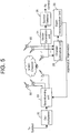
- Figure 5 illustrates the construction of a signal transmission apparatus for a mobile communication system using multiple antennas in accordance with a second embodiment of the present invention.
- the signal transmission apparatus of the second embodiment of the present invention additionally includes a channel estimation unit 28 and an eigen decomposition unit 30.
- the channel estimation unit 28 estimates a channel matrix ( H ) from the signals collected from the plurality of receive antennas 60, and the eigen decomposition unit 30 performs a eigen-decomposition on the estimated channel matrix ( H ) to obtain an eigenvalue and an eigenvector, and then feeds back them to the beamforming unit 22.
- the beamforming unit 22 of the sending end performs a beamforming on the symbols by using the eigenvector value as a weight vector, and at the same time, adjusts transmission power of each symbol in proportion to the eigenvalue.
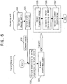
- the MIMO system includes the M number of transmit antennas 50 and the N number of receive antennas 60, and the MIMO system is the FDD system.
- the matrix of mobile communication channel a signal vector transmitted from the sending end passes through is H
- the channel matrix ( H ) is an N x M matrix.
- the sending end/the receiving end transmits a previously agreed pilot symbol or a separate pilot channel
- the receiving end can estimate each component of the channel matrix ( H ) (step S30).
- the eigen decomposition unit 24 performs an eigen-decomposition of the channel matrix ( H ) to obtain an eigenvalue to be fedback and an eigenvector (step S31).
- the channel matrix ( H ) is not a square matrix.
- the eigen decomposition unit 24 of the receiving end is not able to eigen-decompose the channel matrix ( H ) itself, it performs an eigen-decomposition of H H ⁇ H .
- 'H' signifies the Hermitian operation.
- the eigenvector ( e 1 , e 2 , e 3 , ⁇ , e M ) maintains an orthogonality. Thus, even though symbols as many as the transmit antennas are transmitted at one time, notably, the beamforming on each symbol is independent.
- the eigen decomposition unit 24 feeds back the corresponding values to the beamforming unit 22 of the receiving end (step S32).
- the beamforming unit 22 replaces the eigenvectors ( e 1 , e 2 , e 3 , ⁇ , e M ) with weight vectors ( w 1 , w 2 , w 3 , ⁇ , w M ) to perform a beamforming on each symbol (step S33), and transmits the beamformed signal through each transmit antenna 50.
- the beamforming unit 22 can adjust the power of each symbol according to the eigenvalues ( ⁇ 1 , ⁇ 2 , ⁇ 3, , ⁇ , ⁇ M ) and transmits them. Operations after the step S33 are the same as those in the first embodiment of the present invention, descriptions of which are thus omitted.
- estimation of the channel matrix and eigen-decomposition of the channel matrix are all performed in the receiving end, but without being limited thereto, the eigen-decomposition can be also performed in the sending end.
- Figure 7 illustrates the construction of a signal transmission apparatus for a mobile communication system using multiple antennas in accordance with a third embodiment of the present invention.
- the signal transmission apparatus in accordance with the third embodiment of the present invention has such a construction that, rather than both the channel estimation unit 28 and the eigen decomposition unit 30 are positioned in the receiving end, the channel estimation unit 28 is positioned in the receiving end while the eigen decomposition unit 30 is positioned in the sending end.
- the eigen decomposition unit 30 of the sending end performs an eigen-decomposition of the H H ⁇ H to obtain eigenvalues ( ⁇ 1 , ⁇ 2 , ⁇ 3 , ⁇ , ⁇ M ) and eigenvectors ( e 1 , e 2 , e 3 , ⁇ , e M ) (step S42).
- the beamforming unit 22 replaces the eigenvectors ( e 1 , e 2 ,e 3 , ⁇ , e M ) with weight vectors ( w 1 , w 2 , w 3 , ⁇ , w M ), performs a beamforming on each symbol (step S43), and transmits the beamformed signal through each transmit antenna 50 (step S44). Operations after the step S44 are the same as those in the second embodiment of the present invention, descriptions of which are thus omitted.
- the weight vector to be inner-producted to each symbol is received from the receiving end or only the channel matrix is inputted form the receiving end, and then, the corresponding channel matrix is eigen-decomposed to calculate a weight vector.
- FDD frequency division duplex
- FIG. 9 illustrates the construction of a signal transmission apparatus for a mobile communication system using multiple antennas in accordance with a fourth embodiment of the present invention, adopting the FDD system.
- a channel estimation unit 34 for estimating a channel matrix and an eigen decomposition unit 30 for performing an eigen-decomposition are all positioned in the sending/receiving end.
- the channel estimation unit 34 of the sending end estimates a forward channel matrix (H) and the eigen decomposition unit 36 performs an eigen-decomposition of the estimated channel matrix (H) and obtains an eigenvalue and an eigenvector.
- the beamforming unit 22 employs the obtained eigenvector as a weight vector, inner-products each symbol demultiplexed in the demultiplexer 20 by the weight vector, performs a beamforming on each symbol and transmits them.
- the following operations are the same as those after the step S44, descriptions of which are thus omitted.
- the beamforming is performed on each symbol using the correlation as well as the independence between antennas, and then the beamformed symbols are transmitted.
- both the correlation between antennas and the independence between antennas are all considered, so that the gain according to the correlation between antennas can be also obtained.
- the additional gain would lead to enhancement of the symbol detection capability of the sending end, resulting in that performance of the MIMO system can be remarkably heightened.
Landscapes
- Engineering & Computer Science (AREA)
- Computer Networks & Wireless Communication (AREA)
- Signal Processing (AREA)
- Power Engineering (AREA)
- Physics & Mathematics (AREA)
- Mathematical Physics (AREA)
- Mobile Radio Communication Systems (AREA)
- Radio Transmission System (AREA)
Claims (4)
- Signalsendeverfahren für ein Mobilkommunikationssystem mit einer Mehrzahl von Eingängen und einer Mehrzahl von Ausgängen, MIMO, unter Verwendung einer Mehrzahl von Sendeantennen in einem Sendeende, wobei das Verfahren ferner die Schritte umfasst:Demultiplexen, in dem Sendeende, von sequenziell eingegebenen Symbolen;Eigenzerlegen (S42), in dem Sendeende, einer Kanalmatrix, die von einem Empfangsende zurückgegeben wurde;Berechnen (S42), in dem Sendeende, eines Eigenvektors und eines Eigenwerts;Durchführen (S43), in dem Sendeende, einer Strahlbildung bei jedem Symbol, wobei die Strahlbildung durch Multiplizieren von jedem Symbol mit dem Eigenvektor durchgeführt wird, wobei ein Energieniveau von jedem Symbol im Verhältnis zu dem berechneten Eigenwert eingestellt wird;Senden (S44), von dem Sendeende, eines strahlgebildeten Signals, das jedes strahlgebildete Symbol umfasst, durch eine Vielzahl von Sendeantennen (50);Sammeln (S20), bei einem Empfangsende, der gesendeten Signale durch eine Vielzahl von Empfangsantennen (60);Schätzen (S21, S46), in dem Empfangsende, eines Sendevektors aus den gesammelten Signalen unter Verwendung eines Zero-forcing-Verfahrens oder eines Verfahrens mit minimalem mittleren Quadratfehler, MMSE;Durchführen (S22, S47), in dem Empfangsende, einer Strahlbildung bei dem geschätzten Sendevektor und Erfassen eines Sendesymbols;Schätzen (S40) in dem Empfangsende, einer Kanalmatrix aus den gesammelten Signalen; undZurückgeben (S41), von dem Empfangsende, der geschätzten Kanalmatrix zu dem Eigenzerlegungsschritt.
- Verfahren gemäß Anspruch 1, wobei der Eigenvektor in dem Sendeende berechnet wird.
- Signalsendesytem für ein Mobilkommunikationssystem mit einer Mehrzahl von Eingängen und einer Mehrzahl von Ausgängen, MIMO, wobei das System umfasst:ein Sendeende, umfassend:einen Demultiplexer (20), der konfiguriert ist, um sequenziell eingegebene Symbole zu demultiplexen;eine Eigenzerlegungseinheit (32), die konfiguriert ist, um eine Kanalmatrix eigenzuzerlegen, die von einem Empfangsende zurückgegeben ist, und um einen Eigenvektor und einen Eigenwert zu berechnen;eine Strahlbildungseinheit (22), die konfiguriert ist, um eine Strahlbildung bei jedem Symbol durch Multiplizieren von jedem Symbol mit dem berechneten Eigenvektor durchzuführen, wobei ein Energieniveau von jedem Symbol durch die Strahlbildungseinheit im Verhältnis zu dem Eigenwert eingestellt wird; undeine Vielzahl von Sendeantennen (50), die konfiguriert ist, um die strahlgebildeten Signale zu senden, die jedes strahlgebildete Symbol umfassen; undein Empfangsende, umfassend:eine Vielzahl von Empfangsantennen (60), die konfiguriert ist, um die gesendeten strahlgebildeten Signale zu sammeln;eine Vektorschätzeinheit (24), die konfiguriert ist, um einen Sendevektor aus den gesammelten Signalen unter Verwendung eines Zero-forcing-Verfahrens oder eines Verfahrens mit minimalem mittleren quadratischen Fehler, MMSE, zu schätzen;einen Symbolerfasser (25), der konfiguriert ist, um eine Strahlbildung bei dem geschätzten Sendevektor durchzuführen und um ein Sendesymbol zu erfassen; undeine Kanalschätzeinheit (28), die konfiguriert ist, um eine Kanalmatrix aus den gesammelten Signalen zu schätzen und um die geschätzte Kanalmatrix zurück zu der Eigenzerlegeeinheit zurückzugeben.
- System gemäß Anspruch 3, wobei die Eigenzerlegeeinheit, die konfiguriert ist, um den Eigenvektor zu berechnen, nicht in dem Sendeende, sondern in dem Empfangsende umfasst ist.
Applications Claiming Priority (3)
| Application Number | Priority Date | Filing Date | Title |
|---|---|---|---|
| KR2002015358 | 2002-03-21 | ||
| KR10-2002-0015358A KR100464014B1 (ko) | 2002-03-21 | 2002-03-21 | 다중 입출력 이동 통신 시스템에서의 폐루프 신호 처리 방법 |
| PCT/KR2003/000556 WO2003081803A1 (en) | 2002-03-21 | 2003-03-21 | Apparatus and method for transmitting signal in mobile communication system |
Publications (3)
| Publication Number | Publication Date |
|---|---|
| EP1490984A1 EP1490984A1 (de) | 2004-12-29 |
| EP1490984A4 EP1490984A4 (de) | 2010-10-06 |
| EP1490984B1 true EP1490984B1 (de) | 2012-05-02 |
Family
ID=28036150
Family Applications (1)
| Application Number | Title | Priority Date | Filing Date |
|---|---|---|---|
| EP03745025A Expired - Lifetime EP1490984B1 (de) | 2002-03-21 | 2003-03-21 | System und verfahren zum übertragen eines signals in einem mobilkommunikationssystem |
Country Status (7)
| Country | Link |
|---|---|
| US (1) | US7068981B2 (de) |
| EP (1) | EP1490984B1 (de) |
| JP (1) | JP4361808B2 (de) |
| KR (1) | KR100464014B1 (de) |
| CN (1) | CN100440753C (de) |
| AU (1) | AU2003215949A1 (de) |
| WO (1) | WO2003081803A1 (de) |
Families Citing this family (90)
| Publication number | Priority date | Publication date | Assignee | Title |
|---|---|---|---|---|
| US7295509B2 (en) | 2000-09-13 | 2007-11-13 | Qualcomm, Incorporated | Signaling method in an OFDM multiple access system |
| US9130810B2 (en) | 2000-09-13 | 2015-09-08 | Qualcomm Incorporated | OFDM communications methods and apparatus |
| GB0222555D0 (en) * | 2002-09-28 | 2002-11-06 | Koninkl Philips Electronics Nv | Packet data transmission system |
| US6873606B2 (en) * | 2002-10-16 | 2005-03-29 | Qualcomm, Incorporated | Rate adaptive transmission scheme for MIMO systems |
| EP1568155A4 (de) * | 2002-10-29 | 2011-06-22 | Nokia Corp | Strahlformer mit niedriger komplexität für mehrere sende- und empfangsantennen |
| JP4197482B2 (ja) * | 2002-11-13 | 2008-12-17 | パナソニック株式会社 | 基地局の送信方法、基地局の送信装置及び通信端末 |
| US7548522B2 (en) * | 2003-03-27 | 2009-06-16 | Ktfreetel Co., Ltd. | Orthogonal frequency division multiplexing wireless communication operable on frequency selective channel, and channel compensation method |
| JP4212976B2 (ja) * | 2003-07-23 | 2009-01-21 | 富士通株式会社 | Mimo方式の無線通信システム及び無線通信装置 |
| JP2005123788A (ja) * | 2003-10-15 | 2005-05-12 | Sharp Corp | 無線通信装置 |
| US7616698B2 (en) | 2003-11-04 | 2009-11-10 | Atheros Communications, Inc. | Multiple-input multiple output system and method |
| US7680461B2 (en) * | 2003-11-05 | 2010-03-16 | Sony Corporation | Wireless communications system, wireless communications method, and wireless communications apparatus |
| JP4337507B2 (ja) | 2003-11-05 | 2009-09-30 | ソニー株式会社 | 無線通信システム、並びに無線通信装置及び無線通信方法、並びにコンピュータ・プログラム |
| KR100963257B1 (ko) * | 2003-12-05 | 2010-06-10 | 퀄컴 인코포레이티드 | 폐루프 다중 송수신 안테나 이동통신 시스템에서 송신고유 벡터를 선택하여 데이터를 송신하는 장치 및 방법 |
| JP4425925B2 (ja) | 2003-12-27 | 2010-03-03 | 韓國電子通信研究院 | 固有ビーム形成技術を使用するmimo−ofdmシステム |
| KR100690872B1 (ko) * | 2004-01-20 | 2007-03-09 | 엘지전자 주식회사 | 폐루프 mimo 시스템의 신호 전송 방법 |
| JP2007518346A (ja) | 2004-01-20 | 2007-07-05 | エルジー エレクトロニクス インコーポレイティド | Mimoシステムにおける信号送受信方法 |
| CN101764633B (zh) * | 2004-02-11 | 2016-08-17 | Lg电子株式会社 | 发射和接收数据流的方法和系统 |
| US7555053B2 (en) * | 2004-04-14 | 2009-06-30 | Broadcom Corporation | Long training sequence for MIMO WLAN systems |
| EP3313001A1 (de) * | 2004-06-22 | 2018-04-25 | Apple Inc. | Mimo-systeme mit geschlossenem regelkreis und verfahren |
| US7570696B2 (en) * | 2004-06-25 | 2009-08-04 | Intel Corporation | Multiple input multiple output multicarrier communication system and methods with quantized beamforming feedback |
| KR100943610B1 (ko) * | 2004-07-20 | 2010-02-24 | 삼성전자주식회사 | 다중 시공간 블록 부호화 방식을 사용하는 다중 입력 다중 출력 시스템에서 안테나 셔플링 정보 피드백 장치 및 방법 |
| US9137822B2 (en) | 2004-07-21 | 2015-09-15 | Qualcomm Incorporated | Efficient signaling over access channel |
| US9148256B2 (en) | 2004-07-21 | 2015-09-29 | Qualcomm Incorporated | Performance based rank prediction for MIMO design |
| GB2419493A (en) * | 2004-10-19 | 2006-04-26 | Ict Ltd | Communications system utilising feed-back controlled multiple antennas |
| JP4065276B2 (ja) * | 2004-11-12 | 2008-03-19 | 三洋電機株式会社 | 送信方法およびそれを利用した無線装置 |
| KR100950643B1 (ko) | 2004-11-15 | 2010-04-01 | 삼성전자주식회사 | Mimo 통신 시스템과 그 시스템에서의 데이터 송수신방법 및 그 장치 |
| US7649861B2 (en) * | 2004-11-30 | 2010-01-19 | Intel Corporation | Multiple antenna multicarrier communication system and method with reduced mobile-station processing |
| US7822128B2 (en) * | 2004-12-03 | 2010-10-26 | Intel Corporation | Multiple antenna multicarrier transmitter and method for adaptive beamforming with transmit-power normalization |
| US9246560B2 (en) | 2005-03-10 | 2016-01-26 | Qualcomm Incorporated | Systems and methods for beamforming and rate control in a multi-input multi-output communication systems |
| US9154211B2 (en) | 2005-03-11 | 2015-10-06 | Qualcomm Incorporated | Systems and methods for beamforming feedback in multi antenna communication systems |
| US8446892B2 (en) | 2005-03-16 | 2013-05-21 | Qualcomm Incorporated | Channel structures for a quasi-orthogonal multiple-access communication system |
| US9461859B2 (en) | 2005-03-17 | 2016-10-04 | Qualcomm Incorporated | Pilot signal transmission for an orthogonal frequency division wireless communication system |
| US9143305B2 (en) | 2005-03-17 | 2015-09-22 | Qualcomm Incorporated | Pilot signal transmission for an orthogonal frequency division wireless communication system |
| US9520972B2 (en) | 2005-03-17 | 2016-12-13 | Qualcomm Incorporated | Pilot signal transmission for an orthogonal frequency division wireless communication system |
| US7830988B2 (en) | 2005-03-28 | 2010-11-09 | Nec Corporation | MIMO decoder and MIMO decoding method |
| CN1841961A (zh) * | 2005-03-30 | 2006-10-04 | 松下电器产业株式会社 | 多天线无线通信系统中选择发送天线的方法和装置 |
| US9184870B2 (en) | 2005-04-01 | 2015-11-10 | Qualcomm Incorporated | Systems and methods for control channel signaling |
| US9408220B2 (en) | 2005-04-19 | 2016-08-02 | Qualcomm Incorporated | Channel quality reporting for adaptive sectorization |
| US9036538B2 (en) | 2005-04-19 | 2015-05-19 | Qualcomm Incorporated | Frequency hopping design for single carrier FDMA systems |
| US8879511B2 (en) | 2005-10-27 | 2014-11-04 | Qualcomm Incorporated | Assignment acknowledgement for a wireless communication system |
| US8565194B2 (en) | 2005-10-27 | 2013-10-22 | Qualcomm Incorporated | Puncturing signaling channel for a wireless communication system |
| US8611284B2 (en) | 2005-05-31 | 2013-12-17 | Qualcomm Incorporated | Use of supplemental assignments to decrement resources |
| US8462859B2 (en) | 2005-06-01 | 2013-06-11 | Qualcomm Incorporated | Sphere decoding apparatus |
| US7630732B2 (en) * | 2005-06-14 | 2009-12-08 | Interdigital Technology Corporation | Method and apparatus for generating feedback information for transmit power control in a multiple-input multiple-output wireless communication system |
| US7643843B2 (en) * | 2005-06-14 | 2010-01-05 | Interdigital Technology Corporation | Method and system for transmit power control in a multiple-input multiple-output wireless communication system |
| US20070071147A1 (en) * | 2005-06-16 | 2007-03-29 | Hemanth Sampath | Pseudo eigen-beamforming with dynamic beam selection |
| US9179319B2 (en) | 2005-06-16 | 2015-11-03 | Qualcomm Incorporated | Adaptive sectorization in cellular systems |
| US8599945B2 (en) | 2005-06-16 | 2013-12-03 | Qualcomm Incorporated | Robust rank prediction for a MIMO system |
| US8345732B2 (en) * | 2005-06-28 | 2013-01-01 | Broadcom Corporation | Feedback of channel information in a closed loop beamforming wireless communication system |
| US8885628B2 (en) | 2005-08-08 | 2014-11-11 | Qualcomm Incorporated | Code division multiplexing in a single-carrier frequency division multiple access system |
| US9209956B2 (en) | 2005-08-22 | 2015-12-08 | Qualcomm Incorporated | Segment sensitive scheduling |
| US20070041457A1 (en) | 2005-08-22 | 2007-02-22 | Tamer Kadous | Method and apparatus for providing antenna diversity in a wireless communication system |
| US8644292B2 (en) | 2005-08-24 | 2014-02-04 | Qualcomm Incorporated | Varied transmission time intervals for wireless communication system |
| US9136974B2 (en) | 2005-08-30 | 2015-09-15 | Qualcomm Incorporated | Precoding and SDMA support |
| EP1760905A1 (de) * | 2005-09-02 | 2007-03-07 | Mitsubishi Electric Information Technology Centre Europe B.V. | Verfahren zum Regeln von Übertragungssignalen zwischen einer ersten Kommunikationsvorrichtung und einer zweiten Kommunikationsvorrichtung über ein drahtloses Netzwerk |
| US8045512B2 (en) | 2005-10-27 | 2011-10-25 | Qualcomm Incorporated | Scalable frequency band operation in wireless communication systems |
| US8693405B2 (en) | 2005-10-27 | 2014-04-08 | Qualcomm Incorporated | SDMA resource management |
| US9225488B2 (en) | 2005-10-27 | 2015-12-29 | Qualcomm Incorporated | Shared signaling channel |
| US9172453B2 (en) | 2005-10-27 | 2015-10-27 | Qualcomm Incorporated | Method and apparatus for pre-coding frequency division duplexing system |
| US8477684B2 (en) | 2005-10-27 | 2013-07-02 | Qualcomm Incorporated | Acknowledgement of control messages in a wireless communication system |
| US9225416B2 (en) | 2005-10-27 | 2015-12-29 | Qualcomm Incorporated | Varied signaling channels for a reverse link in a wireless communication system |
| US9088384B2 (en) | 2005-10-27 | 2015-07-21 | Qualcomm Incorporated | Pilot symbol transmission in wireless communication systems |
| US9210651B2 (en) | 2005-10-27 | 2015-12-08 | Qualcomm Incorporated | Method and apparatus for bootstraping information in a communication system |
| US8582509B2 (en) | 2005-10-27 | 2013-11-12 | Qualcomm Incorporated | Scalable frequency band operation in wireless communication systems |
| US9144060B2 (en) | 2005-10-27 | 2015-09-22 | Qualcomm Incorporated | Resource allocation for shared signaling channels |
| CN1968043A (zh) * | 2005-11-16 | 2007-05-23 | 松下电器产业株式会社 | 发送分集方法和mimo通信系统 |
| US8582548B2 (en) | 2005-11-18 | 2013-11-12 | Qualcomm Incorporated | Frequency division multiple access schemes for wireless communication |
| US8102830B2 (en) * | 2005-12-16 | 2012-01-24 | Samsung Electronics Co., Ltd. | MIMO radio communication apparatus and method |
| US8831607B2 (en) | 2006-01-05 | 2014-09-09 | Qualcomm Incorporated | Reverse link other sector communication |
| KR100922936B1 (ko) | 2006-02-07 | 2009-10-22 | 삼성전자주식회사 | 통신 시스템에서 데이터 송수신 방법 및 시스템 |
| KR101237384B1 (ko) * | 2006-07-10 | 2013-02-26 | 인하대학교 산학협력단 | 무선 통신 네트워크에서 빔 형성 장치 및 방법 |
| US8233556B2 (en) * | 2006-07-19 | 2012-07-31 | Texas Instruments Incorporated | Reduced feedback transmit beamforming |
| KR100902896B1 (ko) * | 2006-08-18 | 2009-06-15 | 엘지전자 주식회사 | 피드백 정보의 오류에 대비한 신호 송수신 방법 |
| US7787567B2 (en) | 2006-09-26 | 2010-08-31 | Intel Corporation | Beamforming by antenna puncturing |
| US9106296B2 (en) * | 2006-12-19 | 2015-08-11 | Qualcomm Incorporated | Beam space time coding and transmit diversity |
| US20080260051A1 (en) * | 2007-04-23 | 2008-10-23 | Federico Boccardi | Method and apparatus for transmitting information simultaneously to multiple destinations over shared wireless resources |
| US8010140B2 (en) | 2007-10-18 | 2011-08-30 | Samsung Electronics Co., Ltd. | Method of space division multiple access communication using user cooperation and system of enabling the method |
| KR100959645B1 (ko) | 2007-10-31 | 2010-05-26 | 한국전자통신연구원 | 다중사용자 다중입출력 시스템의 송수신 방법 |
| WO2009057876A1 (en) * | 2007-10-31 | 2009-05-07 | Electronics And Telecommunications Research Institute | Transmitting/receiving method for multi-user multiple-input multiple-output system |
| EP2073471A1 (de) * | 2007-12-20 | 2009-06-24 | Sony Corporation | Verbessertes Auswahlkriterium für quantisiertes, vorkodiertes, räumliches MIMO-Multiplexing |
| US8391797B2 (en) | 2008-04-29 | 2013-03-05 | Apple Inc. | Performance for a multiple antenna beamforming cellular network |
| US9755705B2 (en) * | 2008-08-07 | 2017-09-05 | Qualcomm Incorporated | Method and apparatus for supporting multi-user and single-user MIMO in a wireless communication system |
| JP2011158430A (ja) * | 2010-02-03 | 2011-08-18 | Mitsubishi Electric Corp | 送受信ビーム形成装置 |
| US8717430B2 (en) | 2010-04-26 | 2014-05-06 | Medtronic Navigation, Inc. | System and method for radio-frequency imaging, registration, and localization |
| US10050680B2 (en) * | 2010-06-07 | 2018-08-14 | Entropic Communications, Llc | Method and apparatus for real time multiplexing with transmitter and antenna array elements |
| JP5496066B2 (ja) * | 2010-11-22 | 2014-05-21 | 三菱電機株式会社 | 送受信装置 |
| US8587495B2 (en) * | 2010-12-07 | 2013-11-19 | Motorola Solutions, Inc. | Multiple-input multiple-output (MIMO) antenna system |
| CN105432026B (zh) * | 2013-07-30 | 2018-10-30 | Lg电子株式会社 | 在无线通信系统中利用基于部分天线阵列的波束成形执行天线重排的方法及其设备 |
| WO2017164590A1 (ko) * | 2016-03-24 | 2017-09-28 | 엘지전자 주식회사 | 차세대 통신 시스템에서 참조 신호를 송수신하는 방법 및 이를 위한 장치 |
| US10404336B1 (en) * | 2017-07-17 | 2019-09-03 | Marvell International Ltd. | Systems and methods for channel correlation based user detection in an uplink multi-user transmission of a multiple-input multiple-output network |
Family Cites Families (21)
| Publication number | Priority date | Publication date | Assignee | Title |
|---|---|---|---|---|
| JP2965503B2 (ja) * | 1996-02-23 | 1999-10-18 | 株式会社エイ・ティ・アール光電波通信研究所 | アレーアンテナの制御装置 |
| JPH1070494A (ja) * | 1996-08-27 | 1998-03-10 | N T T Ido Tsushinmo Kk | 送信ダイバーシティ用送受信装置 |
| JPH10200321A (ja) | 1997-01-09 | 1998-07-31 | Mitsubishi Electric Corp | 移動体通信基地局用デジタルビームフォーミングアンテナ |
| CA2371384C (en) * | 1999-05-19 | 2006-02-21 | Nokia Networks Oy | Transmit diversity method and system |
| US6901062B2 (en) * | 1999-12-01 | 2005-05-31 | Kathrein-Werke Kg | Adaptive antenna array wireless data access point |
| KR100323877B1 (ko) * | 1999-12-28 | 2002-02-16 | 박승창 | 수신 전파의 이진 데이터에 대한 가중과 라디오주파수송수신 신호 정수의 조정을 병행하는 적응 빔 성형 방법과디지털 빔 성형기 |
| US6888809B1 (en) * | 2000-01-13 | 2005-05-03 | Lucent Technologies Inc. | Space-time processing for multiple-input, multiple-output, wireless systems |
| KR100493068B1 (ko) * | 2000-03-08 | 2005-06-02 | 삼성전자주식회사 | 이동통신시스템에서 피드백 정보를 이용하는 반맹목적방식의 송신안테나어레이 장치 및 방법 |
| US6473467B1 (en) * | 2000-03-22 | 2002-10-29 | Qualcomm Incorporated | Method and apparatus for measuring reporting channel state information in a high efficiency, high performance communications system |
| KR100493150B1 (ko) * | 2000-04-10 | 2005-06-02 | 삼성전자주식회사 | 이동통신을 위한 폐루프 전송 다이버시티의 최적 가중치탐색장치 및 방법 |
| KR100493152B1 (ko) * | 2000-07-21 | 2005-06-02 | 삼성전자주식회사 | 이동 통신 시스템에서의 전송 안테나 다이버시티 방법 및이를 위한 기지국 장치 및 이동국 장치 |
| JP4176463B2 (ja) * | 2000-08-10 | 2008-11-05 | 富士通株式会社 | 送信ダイバーシチ通信装置 |
| JP3559231B2 (ja) * | 2000-08-18 | 2004-08-25 | 日本電信電話株式会社 | 複数ビーム制御適応アンテナ装置及びそれを用いた通信方法 |
| US6778612B1 (en) | 2000-08-18 | 2004-08-17 | Lucent Technologies Inc. | Space-time processing for wireless systems with multiple transmit and receive antennas |
| KR20020041217A (ko) * | 2000-11-27 | 2002-06-01 | 윤종용 | 이동통신시스템에서 칩 레벨 순방향 채널추정을 채용한반맹목적 송신 안테나 어레이 장치 및 방법 |
| GB0102316D0 (en) * | 2001-01-30 | 2001-03-14 | Koninkl Philips Electronics Nv | Radio communication system |
| KR100584625B1 (ko) * | 2001-05-17 | 2006-05-30 | 삼성전자주식회사 | 안테나 어레이를 포함하는 이동 통신 장치 및 방법 |
| US6760388B2 (en) * | 2001-12-07 | 2004-07-06 | Qualcomm Incorporated | Time-domain transmit and receive processing with channel eigen-mode decomposition for MIMO systems |
| KR100777563B1 (ko) * | 2001-12-31 | 2007-11-20 | 주식회사 케이티 | 빔조향 및 전파도래각 추정을 위한 기지국의 송/수신 장치 |
| US7436896B2 (en) * | 2002-01-04 | 2008-10-14 | Nokia Corporation | High rate transmit diversity transmission and reception |
| US7076263B2 (en) * | 2002-02-19 | 2006-07-11 | Qualcomm, Incorporated | Power control for partial channel-state information (CSI) multiple-input, multiple-output (MIMO) systems |
-
2002
- 2002-03-21 KR KR10-2002-0015358A patent/KR100464014B1/ko not_active Expired - Fee Related
-
2003
- 2003-03-21 JP JP2003579386A patent/JP4361808B2/ja not_active Expired - Fee Related
- 2003-03-21 AU AU2003215949A patent/AU2003215949A1/en not_active Abandoned
- 2003-03-21 EP EP03745025A patent/EP1490984B1/de not_active Expired - Lifetime
- 2003-03-21 WO PCT/KR2003/000556 patent/WO2003081803A1/en not_active Ceased
- 2003-03-21 CN CNB038065495A patent/CN100440753C/zh not_active Expired - Fee Related
- 2003-03-21 US US10/392,950 patent/US7068981B2/en not_active Expired - Fee Related
Also Published As
| Publication number | Publication date |
|---|---|
| CN1643812A (zh) | 2005-07-20 |
| WO2003081803A1 (en) | 2003-10-02 |
| KR100464014B1 (ko) | 2004-12-30 |
| US20030181170A1 (en) | 2003-09-25 |
| EP1490984A4 (de) | 2010-10-06 |
| EP1490984A1 (de) | 2004-12-29 |
| AU2003215949A1 (en) | 2003-10-08 |
| JP4361808B2 (ja) | 2009-11-11 |
| KR20030075883A (ko) | 2003-09-26 |
| CN100440753C (zh) | 2008-12-03 |
| JP2005521327A (ja) | 2005-07-14 |
| US7068981B2 (en) | 2006-06-27 |
Similar Documents
| Publication | Publication Date | Title |
|---|---|---|
| EP1490984B1 (de) | System und verfahren zum übertragen eines signals in einem mobilkommunikationssystem | |
| EP2315365B1 (de) | Verfahren, kommunikationssystem und zugehörige ausrüstungen zur datenübertragung | |
| EP1359683B1 (de) | Drahtlose Kommunikation mittels Vielfachsende- und Vielfachempfangs-Antennenanordnung | |
| EP1992083B1 (de) | Adaptive strahllenkungsverfahren zur maximierung der bilanz einer drahtlosen verbindung und reduktion von verzögerungsspreizung mittels mehreren sende- und empfangsantennen | |
| US7266157B2 (en) | Space-time transmit diversity (STTD) for multiple antennas in radio communications | |
| US7715798B2 (en) | Multiplying symbol streams by rectangular matrix of (P/M)×1 vectors | |
| EP1833186A1 (de) | Drahtloses kommunikationssystem | |
| EP1759470B1 (de) | Vorrichtung und verfahren zur strahlformung in einem mehrantennensystem | |
| US20020000948A1 (en) | Semi-blind transmit antenna array device using feedback information and method thereof in a mobile communication system | |
| US8467468B2 (en) | Transmitting and receiving apparatus having plural antenna in multi-user environments and method thereof | |
| US20040042558A1 (en) | Apparatus and method for transmitting and receiving signals using multi-antennas | |
| US20050032521A1 (en) | Method and apparatus for scheduling multiple users in a mobile communication system using multiple transmit/receive antennas | |
| US20070127586A1 (en) | Multiple stream co-phasing for multiple-input-multiple-output (mimo) systems | |
| EP1788721A2 (de) | Vorrichtung und Verfahren zur Bestimmung von Sender-/Empfängerantenne in einem Kommunikationssystem unter Verwendung von mehreren Antennen | |
| EP2266273B1 (de) | Mimo-langsampräkodierungsverfahren und -vorrichtung | |
| US20080089432A1 (en) | Apparatus and method for beamforming in a multiple-input multiple-output system | |
| EP1521383B1 (de) | Verfahren zur Optimierung der Sende-Kovarianz in drahtlosen Verbindungen mit mehreren Antennen | |
| US20070140363A1 (en) | Method of link adaptation in MIMO beamforming systems | |
| EP1742384A1 (de) | MIMO-Übertragungssystem und Verfahren in denen Information mittels Selektion einer bestimmten Antenne übertragen wird | |
| KR100550719B1 (ko) | 다중 입출력 이동 통신 시스템에서의 신호처리 장치 및 방법 | |
| US11115085B1 (en) | MIMO-OFDM system for increasing reliability | |
| KR100475177B1 (ko) | 다중 입출력 이동 통신 시스템에서의 개루프 신호 처리장치 및 방법 | |
| KR100421897B1 (ko) | 이동통신 시스템에서의 신호 송수신 방법 | |
| KR101043808B1 (ko) | 다중 입출력 시스템의 빔형성 장치 및 방법 | |
| KR100983797B1 (ko) | 다중입력 단일출력 다중 사용자 시스템에서의 전송파워 조절 장치 및 그 방법 |
Legal Events
| Date | Code | Title | Description |
|---|---|---|---|
| PUAI | Public reference made under article 153(3) epc to a published international application that has entered the european phase |
Free format text: ORIGINAL CODE: 0009012 |
|
| 17P | Request for examination filed |
Effective date: 20041014 |
|
| AK | Designated contracting states |
Kind code of ref document: A1 Designated state(s): AT BE BG CH CY CZ DE DK EE ES FI FR GB GR HU IE IT LI LU MC NL PT RO SE SI SK TR |
|
| AX | Request for extension of the european patent |
Extension state: AL LT LV MK |
|
| RAP1 | Party data changed (applicant data changed or rights of an application transferred) |
Owner name: LG ELECTRONICS INC. |
|
| A4 | Supplementary search report drawn up and despatched |
Effective date: 20100903 |
|
| 17Q | First examination report despatched |
Effective date: 20110509 |
|
| REG | Reference to a national code |
Ref country code: DE Ref legal event code: R079 Ref document number: 60340813 Country of ref document: DE Free format text: PREVIOUS MAIN CLASS: H04B0007020000 Ipc: H04B0007040000 |
|
| GRAP | Despatch of communication of intention to grant a patent |
Free format text: ORIGINAL CODE: EPIDOSNIGR1 |
|
| RIC1 | Information provided on ipc code assigned before grant |
Ipc: H04L 25/02 20060101ALI20111018BHEP Ipc: H04B 7/04 20060101AFI20111018BHEP Ipc: H04L 25/03 20060101ALI20111018BHEP Ipc: H04B 7/06 20060101ALI20111018BHEP |
|
| RTI1 | Title (correction) |
Free format text: SYSTEM AND METHOD FOR TRANSMITTING SIGNAL IN MOBILE COMMUNICATION SYSTEM |
|
| GRAS | Grant fee paid |
Free format text: ORIGINAL CODE: EPIDOSNIGR3 |
|
| GRAA | (expected) grant |
Free format text: ORIGINAL CODE: 0009210 |
|
| AK | Designated contracting states |
Kind code of ref document: B1 Designated state(s): DE FR GB |
|
| REG | Reference to a national code |
Ref country code: GB Ref legal event code: FG4D |
|
| REG | Reference to a national code |
Ref country code: DE Ref legal event code: R096 Ref document number: 60340813 Country of ref document: DE Effective date: 20120621 |
|
| PLBE | No opposition filed within time limit |
Free format text: ORIGINAL CODE: 0009261 |
|
| STAA | Information on the status of an ep patent application or granted ep patent |
Free format text: STATUS: NO OPPOSITION FILED WITHIN TIME LIMIT |
|
| 26N | No opposition filed |
Effective date: 20130205 |
|
| REG | Reference to a national code |
Ref country code: DE Ref legal event code: R097 Ref document number: 60340813 Country of ref document: DE Effective date: 20130205 |
|
| REG | Reference to a national code |
Ref country code: FR Ref legal event code: ST Effective date: 20131129 |
|
| PG25 | Lapsed in a contracting state [announced via postgrant information from national office to epo] |
Ref country code: FR Free format text: LAPSE BECAUSE OF NON-PAYMENT OF DUE FEES Effective date: 20130402 |
|
| PGFP | Annual fee paid to national office [announced via postgrant information from national office to epo] |
Ref country code: DE Payment date: 20180206 Year of fee payment: 16 Ref country code: GB Payment date: 20180207 Year of fee payment: 16 |
|
| REG | Reference to a national code |
Ref country code: DE Ref legal event code: R119 Ref document number: 60340813 Country of ref document: DE |
|
| GBPC | Gb: european patent ceased through non-payment of renewal fee |
Effective date: 20190321 |
|
| PG25 | Lapsed in a contracting state [announced via postgrant information from national office to epo] |
Ref country code: GB Free format text: LAPSE BECAUSE OF NON-PAYMENT OF DUE FEES Effective date: 20190321 Ref country code: DE Free format text: LAPSE BECAUSE OF NON-PAYMENT OF DUE FEES Effective date: 20191001 |