EP1491158A1 - Support detachable pour une installation de référence d'un système de guidage chirurgical - Google Patents
Support detachable pour une installation de référence d'un système de guidage chirurgical Download PDFInfo
- Publication number
- EP1491158A1 EP1491158A1 EP20040253687 EP04253687A EP1491158A1 EP 1491158 A1 EP1491158 A1 EP 1491158A1 EP 20040253687 EP20040253687 EP 20040253687 EP 04253687 A EP04253687 A EP 04253687A EP 1491158 A1 EP1491158 A1 EP 1491158A1
- Authority
- EP
- European Patent Office
- Prior art keywords
- instrument
- support structure
- reference array
- predefined
- mounting interface
- Prior art date
- Legal status (The legal status is an assumption and is not a legal conclusion. Google has not performed a legal analysis and makes no representation as to the accuracy of the status listed.)
- Granted
Links
- 238000000034 method Methods 0.000 claims description 23
- 230000008878 coupling Effects 0.000 claims description 22
- 238000010168 coupling process Methods 0.000 claims description 22
- 238000005859 coupling reaction Methods 0.000 claims description 22
- 210000003484 anatomy Anatomy 0.000 description 35
- 210000003127 knee Anatomy 0.000 description 10
- 238000001356 surgical procedure Methods 0.000 description 9
- 238000013459 approach Methods 0.000 description 5
- 210000000988 bone and bone Anatomy 0.000 description 5
- 238000011882 arthroplasty Methods 0.000 description 4
- 230000033001 locomotion Effects 0.000 description 4
- 238000005516 engineering process Methods 0.000 description 3
- 239000007943 implant Substances 0.000 description 3
- 210000002303 tibia Anatomy 0.000 description 3
- 230000006978 adaptation Effects 0.000 description 2
- 238000002591 computed tomography Methods 0.000 description 2
- 238000003384 imaging method Methods 0.000 description 2
- 230000004807 localization Effects 0.000 description 2
- 230000013011 mating Effects 0.000 description 2
- 238000011883 total knee arthroplasty Methods 0.000 description 2
- 210000000689 upper leg Anatomy 0.000 description 2
- 238000012795 verification Methods 0.000 description 2
- 238000004164 analytical calibration Methods 0.000 description 1
- 238000003491 array Methods 0.000 description 1
- 238000006073 displacement reaction Methods 0.000 description 1
- 238000005553 drilling Methods 0.000 description 1
- 239000003814 drug Substances 0.000 description 1
- 230000009977 dual effect Effects 0.000 description 1
- 210000003414 extremity Anatomy 0.000 description 1
- 238000002595 magnetic resonance imaging Methods 0.000 description 1
- 238000002324 minimally invasive surgery Methods 0.000 description 1
- 230000000399 orthopedic effect Effects 0.000 description 1
- 238000002600 positron emission tomography Methods 0.000 description 1
- 230000000717 retained effect Effects 0.000 description 1
- 238000002604 ultrasonography Methods 0.000 description 1
Images






Classifications
-
- A—HUMAN NECESSITIES
- A61—MEDICAL OR VETERINARY SCIENCE; HYGIENE
- A61B—DIAGNOSIS; SURGERY; IDENTIFICATION
- A61B17/00—Surgical instruments, devices or methods
- A61B17/16—Instruments for performing osteoclasis; Drills or chisels for bones; Trepans
- A61B17/17—Guides or aligning means for drills, mills, pins or wires
- A61B17/1739—Guides or aligning means for drills, mills, pins or wires specially adapted for particular parts of the body
- A61B17/1764—Guides or aligning means for drills, mills, pins or wires specially adapted for particular parts of the body for the knee
-
- A—HUMAN NECESSITIES
- A61—MEDICAL OR VETERINARY SCIENCE; HYGIENE
- A61B—DIAGNOSIS; SURGERY; IDENTIFICATION
- A61B90/00—Instruments, implements or accessories specially adapted for surgery or diagnosis and not covered by any of the groups A61B1/00 - A61B50/00, e.g. for luxation treatment or for protecting wound edges
- A61B90/39—Markers, e.g. radio-opaque or breast lesions markers
-
- A—HUMAN NECESSITIES
- A61—MEDICAL OR VETERINARY SCIENCE; HYGIENE
- A61B—DIAGNOSIS; SURGERY; IDENTIFICATION
- A61B17/00—Surgical instruments, devices or methods
- A61B17/16—Instruments for performing osteoclasis; Drills or chisels for bones; Trepans
- A61B17/17—Guides or aligning means for drills, mills, pins or wires
- A61B17/1703—Guides or aligning means for drills, mills, pins or wires using imaging means, e.g. by X-rays
-
- A—HUMAN NECESSITIES
- A61—MEDICAL OR VETERINARY SCIENCE; HYGIENE
- A61B—DIAGNOSIS; SURGERY; IDENTIFICATION
- A61B17/00—Surgical instruments, devices or methods
- A61B17/16—Instruments for performing osteoclasis; Drills or chisels for bones; Trepans
- A61B17/17—Guides or aligning means for drills, mills, pins or wires
- A61B17/1725—Guides or aligning means for drills, mills, pins or wires for applying transverse screws or pins through intramedullary nails or pins
-
- A—HUMAN NECESSITIES
- A61—MEDICAL OR VETERINARY SCIENCE; HYGIENE
- A61B—DIAGNOSIS; SURGERY; IDENTIFICATION
- A61B17/00—Surgical instruments, devices or methods
- A61B2017/00477—Coupling
-
- A—HUMAN NECESSITIES
- A61—MEDICAL OR VETERINARY SCIENCE; HYGIENE
- A61B—DIAGNOSIS; SURGERY; IDENTIFICATION
- A61B90/00—Instruments, implements or accessories specially adapted for surgery or diagnosis and not covered by any of the groups A61B1/00 - A61B50/00, e.g. for luxation treatment or for protecting wound edges
- A61B90/39—Markers, e.g. radio-opaque or breast lesions markers
- A61B2090/3983—Reference marker arrangements for use with image guided surgery
Definitions
- the present invention relates to computer assisted navigation and, more specifically, to a detachable support arm which may be used to couple a computer-assisted navigation reference array to an instrument.
- the controlled positioning of surgical instruments is of significant importance in many surgical procedures.
- Various methods and guide instruments have been developed for properly positioning a surgical instrument.
- Such instruments and methods include the use of surgical guides which are properly positioned in relation to one or more anatomical structures and function as mechanical guides for surgical instruments such as, e.g., cutting, reaming, and drilling instruments.
- the use of such surgical guides is common in orthopedic surgical procedures, and such guides may be used to properly locate and align a surgical instrument with respect to a bone when preparing the bone for receiving an implant such as an artificial joint.
- Positioning relative to the bone has typically been aided by using intramedullary instrument systems.
- Intramedullary systems utilize instruments placed within the structure of a bone, for example the intramedullary canal. The instruments provide a temporary positioning reference relative to the bone anatomy.
- Computer-assisted navigational techniques often involve acquiring preoperative images of the relevant anatomical structures and generating an anatomical coordinate system database which represents a three-dimensional model of the anatomical structures.
- the relevant surgical instruments typically have a known and fixed geometry which is also defined in the database preoperatively.
- the position of the instrument being used and the location of one or more nearby anatomical landmarks are registered with the anatomical coordinate system by employing a position sensing system capable of locating instruments and landmarks in all six degrees of freedom.
- a graphical display showing the relative position of the instrument and anatomical structures may then be computed in real time and displayed for the surgeon to assist in properly positioning and manipulating the surgical instrument with respect to the relevant anatomical structures.
- a robotic arm may be used to position and control the instrument, or the surgeon may manually position the instrument, and use the display of the relative position of the instrument and anatomical structure to properly position the instrument.
- Examples of various computer assisted navigation systems are described in U.S. Patent Nos. 5,682,886; 5,921,992; 6,096,050; 6,348,058 B1; 6,434,507 B1; 6,450,978 B1; 6,490,467 B1; and 6,491,699 B1. The disclosures of each of these patents is hereby incorporated herein by reference.
- Surgical instruments have typically been adapted for use with computer-assisted navigation systems by clamping a position reference array that is registrable in the navigation system onto the surgical instrument at an arbitrary position and orientation relative to the instrument. Because the position and orientation is arbitrary, the geometric relationship between the reference array and the surgical instrument must then be calibrated in order to register the combination of the reference array and the surgical instrument in the navigation system and to properly graphically display the relative position of the instrument to the anatomical structure. Thus, each time the reference array is coupled to a surgical instrument, the combination must again be carefully calibrated and registered to ensure the graphical display viewed by the surgeon on the computer-assisted navigation system reflects the actual position and orientation of the instrument relative to the anatomical structure.
- the present invention includes a detachable support arm structure for coupling a computer-assisted navigation system reference array to an instrument, for example a surgical instrument, such that the geometry between the reference array and the surgical instrument is predetermined.
- an instrument for example a surgical instrument
- the geometry between the reference array and the surgical instrument is predetermined.
- the support structure includes a mounting interface that is engageable with a mounting interface on the instrument. Engagement of the mounting interfaces releasably secures the support structure to the instrument in a predefined position in each of six degrees of freedom relative to the support structure thereby fixing the geometry of the support structure relative to the instrument in each of the six degrees of freedom.
- Predefined position is defined as a predetermined location and orientation in all six degrees of freedom which is accurately repeatable.
- the reference array includes at least one reference element and is releasably securable to the support structure.
- the reference array secures to the support structure in a predefined position and orientation in each of six degrees of freedom.
- the array and support structure accurately and repeatably form the same predefined geometry.
- the coupling of the support structure to both the instrument and reference array forms a predefined geometry that is accurate and repeatable in each of six degrees of freedom.
- the support structure comprising a support arm in the exemplary embodiment, for a reference array may be used to adapt instruments for use with computer-assisted navigation systems.
- the support structure may be used for instruments used in a wide range of fields, for example, medicine, biology, electronics, micromachinery, and other such fields requiring accurate positioning of tools or instruments, the support structure is hereinafter described with reference to surgical instruments and computer-assisted surgical navigation systems.
- the support arm structure includes a mounting interface that is engageable with a companion mounting interface on a surgical instrument. Additionally, the support arm supports at least one reference element that is registrable in the computer-assisted navigation system. In one exemplary embodiment, the reference elements are disposed on a reference array that includes at least three reference elements, the array being releasably securable to the support arm structure.
- the support arm, reference array, and instrument all have a predefined geometry that is registered with the navigation system.
- the mounting interfaces connecting the support arm structure to the instrument and the reference array to the support arm structure accurately and repeatably locate and orient the components relative to one another such that upon coupling the reference array to the support arm structure and the support arm structure to the instrument, the predefined geometry is formed.
- the predefined geometry for an instrument and the associated support structure and reference array may be supplied to the navigation system once and then retained by the navigation system.
- the assembly does not need to be recalibrated with the navigation system, rather the assembly only need be verified to ensure a component has not been bent or otherwise damaged, thus altering the predefined geometry known to the computer-assisted navigation system.
- Exemplary embodiments of a detachable support arm for a surgical navigation system reference array include those having a dovetailed mounting surface and threaded fastener receptacle that may be used to lockingly engage a reference array in a predefined and accurately repeatable manner. Additionally, certain support arm structures in accordance with the present invention include a mounting interface for releasably engaging the instrument and which allows for accurate repeatable coupling of the support arm to the instrument to ensure that a predefined geometric relationship between the support arm and instrument is provided upon each coupling.
- the mounting interface between the support arm structure and the instrument includes a cannulated cylindrical boss having a threaded fastener extending therethrough for locating and fixing the support arm structure to a mating interface on the instrument.
- the mounting interface can further include a small cylindrical pin for locating the support arm structure rotationally relative to the axis formed by the cylindrical locating boss.
- the support arm structure may define a length, bend, curve, or other geometry such that the reference array is displaced in a desirable position relative to the instrument so as to not hinder the surgeon's use or interfere with nearby anatomical structure or other instrumentation. Additionally, the support arm structure's geometry positions the reference array to provide the necessary orientation and line of sight with the navigation system sensors for accurate registration in and use with the navigation system.
- Embodiments of the support arm structure may be designed for a specific surgical instrument, for example, a distal femoral cut guide, a profile femoral cut guide, and a proximate tibial cut guide as are used in partial or total knee arthroplasty.
- a specific surgical instrument for example, a distal femoral cut guide, a profile femoral cut guide, and a proximate tibial cut guide as are used in partial or total knee arthroplasty.
- a specific surgical instrument for example, a distal femoral cut guide, a profile femoral cut guide, and a proximate tibial cut guide as are used in partial or total knee arthroplasty.
- Such a procedure is disclosed by a paper on an intramedullary surgical approach for a partial knee arthroplasty entitled "The M/GTM Unicompartmental Knee Minimally Invasive Surgical Technique," available from Zimmer, Inc., of Warsaw, Indiana, the disclosure of which is
- one embodiment of the support arm structure is designed to engage either of two mounting interfaces associated with a proximal tibial cut guide and includes a double dovetail mounting interface for the reference array.
- the plurality of predefined geometries that may be formed by selecting which interfaces to couple allow the support arm structure to be used for both medial and lateral approaches for proximal tibial preparation in a total or partial knee arthroplasty.
- a first exemplary embodiment of the present invention includes an apparatus usable with a computer-assisted navigation system, the apparatus including an instrument; a support structure releasably exchangeable with the instrument in a first predefined position; and at least one reference element disposed with the support structure in a second predefined position, the at least one reference element being registrable in the computer-assisted navigation system; the first and second predefined position and the support structure comprising a first geometry of the at least one reference element relative to the instrument in each of six degrees of freedom.
- a system usable with a computer-assisted navigation system including a plurality of instruments; a support structure engageable with each of the plurality of instruments wherein engagement of the support structure with a selected one of the plurality of instruments releasably secures the support structure to the selected one of the plurality of instruments in a first predefined position; and at least one reference element disposed with the support structure in a second predefined position, the at least one reference element being registrable in the computer-assisted navigation system; the first and second predefined position and the support structure comprising a first predefined geometry of the at least one reference element relative to the one of the plurality of instruments in each of six degrees of freedom.
- a method of preparing an instrument including the steps of providing a support structure which is accurately and releasably engageable to the instrument in a second predefined geometry relative to the instrument; providing a reference array having at least one reference element disposed therewith, the reference element having a third predefined geometry and being registrable in the computer-assisted navigation system; releasably coupling the support structure to the instrument; releasably coupling the reference array to the support structure in a fourth predefined geometry wherein the first, second, third, and fourth geometry define a known spatial relationship of the at least one reference element and the instrument in the computer-assisted navigation system.
- Fig. 1A is a perspective view of an operating room arrangement having a computer-aided navigation system utilizing a detachable support arm for a surgical navigation system reference array in accordance with the present invention
- Fig. 1B is a partial perspective view of the surgical arrangement of Fig 1A showing a surgical apparatus including the detachable support arm;
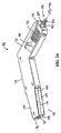
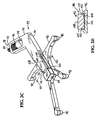
- FIGS. 2A, 2B, 2C, and 2E are perspective views of a first exemplary embodiment support arm structure according to the present invention.
- Fig. 2D is a cross-sectional view of the first exemplary embodiment of Fig. 2C;
- FIGs. 3A and 3B are perspective views of a surgical apparatus including a second embodiment support arm structure according to the present invention.
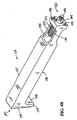
- Figs. 4A and 4B are perspective views of a second embodiment support arm structure shown in Figs. 3A and 3B;
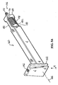
- Figs. 5A and 5B are perspective views of a third embodiment support arm structure according to the present invention.
- Fig. 1A shows an operating room arrangement having computer-assisted navigation system 20 for aiding surgical procedures performed on patient 34.
- Apparatus 40 is usable with computer-assisted navigation system 20 and, referring to Fig. 1B, more specifically includes support arm structure 42 for coupling surgical instrument 44 and navigation system reference array 46.
- Computer-assisted navigation system 20 (Fig. 1A) is used to provide a graphical representation of the position of surgical instrument 44 (Fig. 1B) or another medical instrument relative to the anatomical structures of patient 34.
- Navigation system 20 may include display 22, CPU 24, keyboard 26 and reference locator 28.
- CPU 24 and reference locator 28 determine the position and orientation of surgical instrument 44 by detecting the position and orientation of connected navigation system reference array 46 and knowing the geometry of array 46 and instrument 44.
- Display of a graphical image to represent the current position of instrument 44 may be overlaid on a fluoroscopic image of anatomical structures of patient 34 on display 22.
- Such a computer-assisted navigation system is described in the disclosure of U.S. Patent No. 6,470,207 B1 which is hereby incorporated herein by reference.
- Computer-assisted navigation systems are known in the art which provide for the registration of anatomical structures of patient 34 with a three-dimensional model representing the structure.
- Calibration for localization of instrument 44 facilitates the display of the relative positions of instrument 44 and anatomical structures, for example, the exemplary systems disclosed by U.S. Patent Nos. 6,236,875 B1 and 6,167,145, and U.S. Patent Application to Grimm et al. entitled "Implant Registration Device for Surgical Navigation System," Serial No. 10/357,754, filed February 4, 2003, the disclosures of which are hereby incorporated herein for reference.
- a tracking device such as navigation system reference array 46, shown in Figs. 1A and 1B, enables the calibration and localization of surgical instrument 44 and the tracking of the instrument motion with respect to anatomical structures of patient 34, which has also been located by navigation system 20.
- reference locator 28, shown in Fig. 1A includes emitter 30 and sensors 32 for illuminating and detecting the location of reference elements 48 (Fig. 1B) which are arranged nonlinearly on navigation system reference array 46.
- emitter 30 may direct infrared light toward reference elements 48.
- Reference elements 48 passively reflect the light and are detected and positionally located by sensors 32, thereby allowing processor 24 to calculate the position and orientation of surgical instrument 44 for display relative to an image of the anatomical structures of patient 34 on display 22.
- sensors 32 are charged couple devices.
- reference array 46 is fixed relative to instrument 44.
- various instruments including cutting guides must be located relative to anatomical landmarks, e.g., the mechanical axis of the femur and tibia, in order to prepare the femur and tibia for a knee arthroplasty.
- anatomical landmarks e.g., the mechanical axis of the femur and tibia
- Such a procedure is described in "The M/GTM Unicompartmental Knee Minimally Invasive Surgical Technique," available from Zimmer, Inc., of Warsaw, Indiana, the disclosure of which is hereby incorporated herein by reference.
- surgical instrument 44 is depicted as a proximal tibial cutting guide located just below knee 50 of patient 34 and is useful for guiding a reciprocating saw blade used for preparing the tibial plateau to receive an implant device.
- the exemplary surgical instrument 44 includes cutting guide 52, block 54, and stem 56.
- Cutting guide 52 is coupled to mounting block 54 by stem 56 and may be held in position by pin 58 of extramedullary frame 60 which is coupled to patient 34 by clamp 62.
- inventive support arm structure 42 releasably couples reference array 46 to instrument 44, thereby allowing for real-time graphical positioning of cutting guide 52 relative to anatomical structures of patient 34 by viewing the images displayed on display 22 (Fig. 1A) of navigation system 20.
- Support arm structure 42 advantageously provides a predefined geometry when coupled with surgical instrument 44 and reference array 46.
- Support structure 42 may be used to repeatably and accurately couple reference array 46 to surgical instrument 44, each time providing the same geometry in all six degrees of freedom and eliminating degrees of uncertainty.
- support arm structure 42 allows for adaptation of traditional surgical instruments for dual use for traditional and computer-assisted surgical techniques.
- support arm structure 42 is sized and shaped to position reference array 46 conveniently away from cutting guide 52 and anatomical structures of patient 34 while orienting reference array 46 within line-of-sight of and for accurate positioning by reference locator 28 (Fig. 1A).
- First embodiment support arm structure 42 positions reference array 46 above and medially from cutting guide 52 in a position that does not encumber cutting or interfere with anatomical structures of patient 34.
- support arm structure 42 includes first extension portion 70 defining first end 72 and second extension portion 74 oriented approximately 45° relative to first extension portion 70 and defining second end 76.
- First end 72 includes instrument mounting interface 78 for removably coupling support arm structure 42 to one of mounting interfaces 79 of instrument 44 (one of which is shown in Fig. 1B, the other of which support arm 42 is shown coupled to).
- Instrument mounting interface 78 is configured to accurately and repeatably position and couple support arm structure 42 to instrument 44 in all six degrees of freedom.
- instrument mounting interface 78 includes boss 80, threaded fastener 82, and rotational locating pin 84.
- boss 80 may be asymmetrical, thereby eliminating the requirement for pin 84, and threaded fastener 82 could be another form of fastener and located outside of boss 80.
- Boss 80 is a cylinder protruding from first end 72 and includes a passageway therethrough for extension of threaded fastener 82.
- mounting interface 79 defined on mounting block 54 of instrument 44, includes threaded bore 88 having a counterbore forming boss receptacle 86 for receiving boss 80 and threaded fastener 82 of instrument mounting interface 78.
- the dimensional tolerances of first end 72, boss 80, and boss receptacle 86 are sufficiently tight to provide accurate coupling in five degrees of freedom when instrument mounting interface 78 is coupled to mounting interface 79 and threaded fastener 82 secures support arm structure 42 to mounting block 54.
- pin 84 which is laterally offset from boss 80 and protrudes from first end 72, engages with tight tolerance into pin receptacle 92 of mounting interface 79 (Fig. 1B). Engagement of pin 84 into receptacle 92 completes the locating of support arm structure 42 relative to mounting block 54, and therefore cutting guide 52.
- First extension portion 70 defines cutout 94 in which knurled knob 96 for engaging threaded fastener 82 with threaded fastener 82 with threaded bore 88 (Fib. 1B), is disposed. Tightening fastener 82 to bore 88 completes the fixing of support arm structure 42 relative to mounting block 54.
- second extension portion 74 of support arm structure 42 defines reference array mounting interface 98 at second end 76.
- mounting interface 98 which defines oppositely facing dovetail portions 102 and 104 (Fig. 2D), engages support arm structure 42 to mounting interface 100 , which defines dovetail receptacle 101, of reference array 46.
- Mounting interfaces 98 and 100 are designed to accurately position and couple support arm structure 42 and reference array 46 in a predefined geometry.
- array mounting interface 98 defines top and bottom male dovetail portions 102 and 104, each of which are receivable by female dovetail receptacle 101 (Fig. 2D) defined by mounting interface 100 of reference array 46.
- Second extension portion 74 tapers along top and bottom dovetails 102 and 104 in the direction of second end 76. Additionally, second extension portion 74 widens between both intersection 110 and top surface 106 (defining top dovetail 102) and intersection 110 and bottom surface 108 (defining bottom dovetail 104). Thus, as top or bottom dovetail 102 or 104 is received into oppositely tapered female dovetail 101 (Fig. 2D), a tightly toleranced locking arrangement is provided. Additionally, second end 76 of support arm structure 42 defines threaded hole 112 for receiving fastener 114 of reference array 46 (Fig. 2C), thereby accurately positioning and fixing second end 76 against stop 116 defined in reference array 46 at the interior end of mounting interface 100.
- mounting interface 98 and 100 provide a releasable and repeatably accurate coupling with a predefined geometry between reference array 46 and support arm structure 42.
- the double dovetail design in combination with a support arm structure that is nonlinear, i.e. , includes first portion 70 and second portion 74 offset by approximately 45°, provides a single support arm structure that may be used to extend and offset reference array 46 from instrument 44 in two predefined positional geometries, as can be understood by comparing Figs. 2C and 2E.
- surface 106 (Fig. 2D) faces array 46 and dovetail 102 is engaged with dovetail receptacle 101 (Fig.
- Support arm structure 42 advantageously provides a means of releasably fixing reference array 46 relative to instrument 44 in a predefined geometry, thereby eliminating the requirement to calibrate surgical instrument 44 with navigation system 20 each time surgical instrument 44 is employed.
- Calibration typically includes verifying the location of multiple landmarks on an instrument. Instead, apparatus 40 formed by reference array 46, support arm structure 42, and instrument 44 need only be registered by a verification process that allows navigation system 20 to determine which of the two predefined geometries defined by top and bottom dovetails 102 and 104 are being utilized and to ensure no component has been bent or otherwise damaged. For example, verification may involve verifying the location of only one landmark on instrument 44.
- extramedullary frame 60 provides support for instrument 44 while support arm structure 42 and reference array 46 aid the positioning of cutting guide 52.
- the location and orientation of cutting guide 52 is determined by navigation system 20, thereby providing for display of the geometry of cutting guide 52 relative to anatomical structures of patient 34.
- reference array 46 would be coupled to the bottom dovetail 104 rather than the top dovetail 102 as shown, and support arm structure 42 would be coupled to mounting interface 79 adjacent the mounting interface that support arm structure 42 is shown coupled to in Fig. 1B, thereby again positioning reference array 46 parallel to supinely oriented patient 34, including locating reference array 46 above the tibia (not shown) and away from cutting guide 52 and anatomical structures of patient 34.
- anatomical structures of patient 34 are generally represented on display 22 of navigation system 20 by a graphical model that may include a fluoroscopic image of anatomical structures
- other methods of display may be used, such as acquiring a series of two-dimensional images of anatomical structures of patient 34 and modeling a three-dimensional form that may then be used to generate displays of anatomical structures for various perspectives for preoperative planning purpose and intraoperative navigational purposes.
- a variety of technologies which may be employed to generate such a model of the anatomical structure are well known in the art and include computed tomography (CT), magnetic resonance imaging (MRI), positron emission tomography (PET), ultrasound scanning, and fluoroscopic imaging technologies.
- CT computed tomography
- MRI magnetic resonance imaging
- PET positron emission tomography
- the model of the anatomical structures of patient 34 obtained by such imaging technology can be used for the intraoperative guidance of an instrument such as instrument 44 by facilitating the determination and display of the relative position and orientation of instrument 44 with respect to one or more actual anatomical structures.
- the model of the relevant anatomical structure is a set of two-dimensional images having known spatial relationships, several such images may be simultaneously displayed during the surgical procedure. By also displaying the position of instrument 44 in the images and displaying the images taken from different perspectives, e.g.
- a coordinate system defined by the actual anatomical structure includes data concerning the fixed size and shape of instrument 44, or a relevant portion thereof, which will be used in the image-guided procedure and also to predefine the geometry of reference array 46 and support arm structure 42 relative to cutting guide 52, thereby allowing processor 24 to locate and position cutting guide 52 relative to anatomical structures of patient 34.
- Registration of both anatomical structures and instrument 44 allows relative position and orientation of instrument 44 to be communicated to the surgeon by displaying images of anatomical structures of patient 34 and instrument 44 based on the three-dimensional models of anatomical structures of patient 34 and instrument 44. Additionally, relative positions may be displayed on display 22 using numerical or graphic information other than two or three-dimensional modeling that may aid the surgeon in properly locating instrument 44 relative to the anatomical structure(s).
- reference elements 48 are passive, reflecting infrared light from source 30 (Fig. 1A) to sensors 32.
- reference elements 48 may also be active, for example, infrared emitters detectable by sensors 32.
- Other localizing systems e.g. , radiofrequency or visible light systems, may also be used.
- apparatus 122 includes second exemplary embodiment support arm structure 124 for coupling instrument 126, in this embodiment a femoral profile cut guide, and reference array 46.
- Support arm structure 124 may be coupled to either one of two predefined positions 128a and 128b, thereby providing an option to the surgeon for the direction of offset in which reference array 46 is oriented relative to instrument 126.
- Support arm structure 124 may be advantageously designed especially for use with surgical instrument 126 and may include mounting interface 130, shown in Fig. 4B.
- Mounting interface 130 is designed to only physically be couplable with a matching mounting interface located at predetermined positions 128a and 128b of instrument 126.
- support arm structure 124 may be designed to be coupled with a number of different surgical instruments, thereby reducing the number of reference arrays 46 and support arm structures 124 necessary to complete surgical procedures.
- second exemplary embodiment support arm structure 124 has body 125 generally in the shape of a rectangular bar and having a first end 132 upon which mounting interface 130 is disposed.
- An opposite second end 134 defines rectangular extension 136 oriented 90° to body 125 and extending downward in the direction of bottom surface 138 of support arm structure 124.
- Second end 134 defines male dovetail mounting interface 140 and threaded receptacle 142 thereon.
- first end 132 includes mounting interface 130 for coupling support arm structure 124 to instrument 126 (Fig. 3A and 3B) in a releasable and repeatably accurate predefined geometry.
- Mounting interface 130 may include cylindrical boss 144 protruding from first end 132 and having threaded fastener 146 passing therethrough, and rotational locating pin 148 protruding from first end 132 and laterally adjacent to boss 144.
- Mounting interface 130 functions as described for instrument mounting interface 78 (Fig. 2A) discussed above.
- Support arm structure 124 may also define opening 148 forming links 150 on opposite sides and connecting first end 132 to body 125 of support arm structure 124.
- Knurled knob 152 for rotatably engaging threaded fastener 146 is disposed in opening 148.
- male dovetail mounting interface 140 is tapered and otherwise shaped similar to each of top and bottom dovetail 102 and 104 (Fig. 2B) and releasably and repeatably accurately engages mating female dovetail mounting interface 100 (Fig. 2D) defined by reference array 46.
- Threaded receptacle 142 defined in second end 134 (Fig. 4A) is used to draw end surface 154 of rectangular extension 136 against stop 116 (Fig. 3B) of reference array 46.
- Third embodiment support arm structure 160 shown in Figs. 5A and 5B is similar in design to second exemplary embodiment support arm 124 shown in Figs. 4A and 4B.
- rectangular extension 162 upon which male dovetail mounting interface 164 and threaded receptacle 142 are defined, is oriented 90° relative to longitudinal axis 166 from the orientation of dovetail 140 of second embodiment support arm structure 124 shown in Figs. 4A.
- first end 168 which is located opposite rectangular extension 162
- support arm structure 160 is narrower along at least one axis and is therefore more rectangular in cross-section than second embodiment support arm structure 124, shown most clearly at first end 132 of Fig. 4B.
- first end 168 of third embodiment support arm structure 160 includes boss 170, threaded fastener 172 and rotational locating pin 174 defining instrument mounting interface 176. Also, knurled knob 178 is disposed in cutout 180 formed by oppositely located links 182.
- support arm structure 160 may be configured as desired to provide the necessary displacement, offset and engagement required for a specific surgical instrument and procedure for which it is designed.
Landscapes
- Health & Medical Sciences (AREA)
- Surgery (AREA)
- Life Sciences & Earth Sciences (AREA)
- Biomedical Technology (AREA)
- Medical Informatics (AREA)
- Veterinary Medicine (AREA)
- Oral & Maxillofacial Surgery (AREA)
- Engineering & Computer Science (AREA)
- Public Health (AREA)
- Heart & Thoracic Surgery (AREA)
- Nuclear Medicine, Radiotherapy & Molecular Imaging (AREA)
- Molecular Biology (AREA)
- Animal Behavior & Ethology (AREA)
- General Health & Medical Sciences (AREA)
- Dentistry (AREA)
- Orthopedic Medicine & Surgery (AREA)
- Pathology (AREA)
- Surgical Instruments (AREA)
Applications Claiming Priority (2)
| Application Number | Priority Date | Filing Date | Title |
|---|---|---|---|
| US603007 | 1996-02-16 | ||
| US10/603,007 US6932823B2 (en) | 2003-06-24 | 2003-06-24 | Detachable support arm for surgical navigation system reference array |
Publications (2)
| Publication Number | Publication Date |
|---|---|
| EP1491158A1 true EP1491158A1 (fr) | 2004-12-29 |
| EP1491158B1 EP1491158B1 (fr) | 2011-06-08 |
Family
ID=33418646
Family Applications (1)
| Application Number | Title | Priority Date | Filing Date |
|---|---|---|---|
| EP04253687A Expired - Lifetime EP1491158B1 (fr) | 2003-06-24 | 2004-06-18 | Support detachable pour une installation de référence d'un système de guidage chirurgical |
Country Status (6)
| Country | Link |
|---|---|
| US (1) | US6932823B2 (fr) |
| EP (1) | EP1491158B1 (fr) |
| JP (1) | JP2005013737A (fr) |
| AT (1) | ATE511808T1 (fr) |
| AU (1) | AU2004202764B2 (fr) |
| CA (1) | CA2467532C (fr) |
Cited By (3)
| Publication number | Priority date | Publication date | Assignee | Title |
|---|---|---|---|---|
| EP1570802A3 (fr) * | 2004-03-05 | 2006-06-07 | Zimmer Technology, Inc. | Crochet ajustable pour un élément de poursuite navigé |
| WO2009134720A1 (fr) * | 2008-04-29 | 2009-11-05 | Civco Medical Instruments Co., Inc. | Console pour monter au moins un capteur de position sur une sonde ultrasonore |
| CN105147395A (zh) * | 2015-08-31 | 2015-12-16 | 北京天智航医疗科技股份有限公司 | 一种用于导航手术的光学跟踪工具 |
Families Citing this family (83)
| Publication number | Priority date | Publication date | Assignee | Title |
|---|---|---|---|---|
| US7635390B1 (en) | 2000-01-14 | 2009-12-22 | Marctec, Llc | Joint replacement component having a modular articulating surface |
| US7708741B1 (en) | 2001-08-28 | 2010-05-04 | Marctec, Llc | Method of preparing bones for knee replacement surgery |
| US9155544B2 (en) | 2002-03-20 | 2015-10-13 | P Tech, Llc | Robotic systems and methods |
| US7094241B2 (en) | 2002-11-27 | 2006-08-22 | Zimmer Technology, Inc. | Method and apparatus for achieving correct limb alignment in unicondylar knee arthroplasty |
| US20040153066A1 (en) * | 2003-02-03 | 2004-08-05 | Coon Thomas M. | Apparatus for knee surgery and method of use |
| FR2852223B1 (fr) * | 2003-03-11 | 2005-06-10 | Perception Raisonnement Action En Medecine | Instrument de reperage de la position d'un plan de coupe |
| US7153308B2 (en) * | 2003-05-14 | 2006-12-26 | Ge Medical Systems Global Technology Company, Llc | Universal attachment mechanism for attaching a surgical tracking device to an instrument |
| US7753910B2 (en) * | 2003-07-21 | 2010-07-13 | Stephen Ritland | Surgical image tracker mounting base apparatus and method of use |
| US7764985B2 (en) * | 2003-10-20 | 2010-07-27 | Smith & Nephew, Inc. | Surgical navigation system component fault interfaces and related processes |
| US7771436B2 (en) * | 2003-12-10 | 2010-08-10 | Stryker Leibinger Gmbh & Co. Kg. | Surgical navigation tracker, system and method |
| US7873400B2 (en) | 2003-12-10 | 2011-01-18 | Stryker Leibinger Gmbh & Co. Kg. | Adapter for surgical navigation trackers |
| US7641661B2 (en) | 2003-12-26 | 2010-01-05 | Zimmer Technology, Inc. | Adjustable resection guide |
| US7383164B2 (en) * | 2004-03-05 | 2008-06-03 | Depuy Products, Inc. | System and method for designing a physiometric implant system |
| US8114086B2 (en) | 2004-03-08 | 2012-02-14 | Zimmer Technology, Inc. | Navigated cut guide locator |
| US7993341B2 (en) | 2004-03-08 | 2011-08-09 | Zimmer Technology, Inc. | Navigated orthopaedic guide and method |
| JP2007531596A (ja) * | 2004-03-31 | 2007-11-08 | スミス アンド ネフュー インコーポレーテッド | 基準アレイ入力装置を提供する方法及び装置 |
| US8167888B2 (en) * | 2004-08-06 | 2012-05-01 | Zimmer Technology, Inc. | Tibial spacer blocks and femoral cutting guide |
| US20060200158A1 (en) * | 2005-01-29 | 2006-09-07 | Farling Toby N | Apparatuses and methods for arthroplastic surgery |
| US20060235290A1 (en) * | 2005-04-04 | 2006-10-19 | Aesculap Ag & Co. Kg | Method and apparatus for positioning a cutting tool for orthopedic surgery using a localization system |
| WO2006111964A2 (fr) | 2005-04-18 | 2006-10-26 | Denx, Advanced Medical Systems Ltd. | Procedes et appareil pour implantation dentaire |
| US7840256B2 (en) | 2005-06-27 | 2010-11-23 | Biomet Manufacturing Corporation | Image guided tracking array and method |
| US7643862B2 (en) | 2005-09-15 | 2010-01-05 | Biomet Manufacturing Corporation | Virtual mouse for use in surgical navigation |
| US7835784B2 (en) | 2005-09-21 | 2010-11-16 | Medtronic Navigation, Inc. | Method and apparatus for positioning a reference frame |
| DE102005047895B4 (de) * | 2005-10-06 | 2009-04-09 | Aesculap Ag | Verfahren und Einrichtung zur Bestimmung der Lage eines Gegenstandes |
| US8864686B2 (en) * | 2005-12-01 | 2014-10-21 | Orthosensor Inc. | Virtual mapping of an anatomical pivot point and alignment therewith |
| US8814810B2 (en) * | 2005-12-01 | 2014-08-26 | Orthosensor Inc. | Orthopedic method and system for mapping an anatomical pivot point |
| US7520880B2 (en) | 2006-01-09 | 2009-04-21 | Zimmer Technology, Inc. | Adjustable surgical support base with integral hinge |
| US7744600B2 (en) | 2006-01-10 | 2010-06-29 | Zimmer Technology, Inc. | Bone resection guide and method |
| US7780671B2 (en) | 2006-01-23 | 2010-08-24 | Zimmer Technology, Inc. | Bone resection apparatus and method for knee surgery |
| US20070186738A1 (en) * | 2006-01-31 | 2007-08-16 | Zimmer Technology, Inc. | Tibial cut guide assembly having rotatable cut guide body |
| US20070233156A1 (en) * | 2006-02-16 | 2007-10-04 | Robert Metzger | Surgical instrument |
| US8323290B2 (en) | 2006-03-03 | 2012-12-04 | Biomet Manufacturing Corp. | Tensor for use in surgical navigation |
| US7556428B2 (en) * | 2006-04-14 | 2009-07-07 | Xoran Technologies, Inc. | Surgical navigation system including patient tracker with removable registration appendage |
| US8560047B2 (en) | 2006-06-16 | 2013-10-15 | Board Of Regents Of The University Of Nebraska | Method and apparatus for computer aided surgery |
| US9079010B2 (en) * | 2006-08-30 | 2015-07-14 | Nexstim Oy | Transcranial magnetic stimulation induction coil device with attachment portion for receiving tracking device |
| US7854232B2 (en) * | 2006-08-30 | 2010-12-21 | Nexstim Oy | Transcranial magnetic stimulation induction coil device with attachment portion for receiving tracking device |
| US8543188B2 (en) * | 2006-10-17 | 2013-09-24 | General Electric Company | Method and apparatus for calibrating medical devices |
| CA2679369A1 (fr) * | 2006-11-17 | 2008-05-29 | Smith & Nephew, Inc. | Fixation de cadre de reference |
| US20080140081A1 (en) * | 2006-12-04 | 2008-06-12 | Zimmer, Inc. | Cut guides |
| US8357165B2 (en) * | 2006-12-22 | 2013-01-22 | Depuy Products, Inc. | Reference array mounting bracket for use with a computer assisted orthopaedic surgery system |
| US8814874B2 (en) | 2007-02-13 | 2014-08-26 | Medtronic Navigation, Inc. | Navigated cut guide for total knee reconstruction |
| US8934961B2 (en) | 2007-05-18 | 2015-01-13 | Biomet Manufacturing, Llc | Trackable diagnostic scope apparatus and methods of use |
| JP5171193B2 (ja) | 2007-09-28 | 2013-03-27 | 株式会社 レキシー | 人工膝関節置換手術の術前計画用プログラム |
| AU2008324691A1 (en) * | 2007-11-08 | 2009-05-14 | Orthosoft Inc. | Trackable reference device for computer-assisted surgery |
| US8571637B2 (en) | 2008-01-21 | 2013-10-29 | Biomet Manufacturing, Llc | Patella tracking method and apparatus for use in surgical navigation |
| DE102009007291A1 (de) * | 2009-01-27 | 2010-07-29 | Aesculap Ag | Chirurgische Referenzierungseinheit, chirurgisches Instrument und chirurgisches Navigationssystem |
| EP2470102B1 (fr) | 2009-08-27 | 2016-07-20 | Brainlab AG | Réseau de référence jetable et radio-transparent pour un suivi optique |
| EP2566392A4 (fr) | 2010-05-04 | 2015-07-15 | Pathfinder Therapeutics Inc | Système et procédé d'appariement de surfaces abdominales à l'aide de pseudo-caractéristiques |
| US9498231B2 (en) | 2011-06-27 | 2016-11-22 | Board Of Regents Of The University Of Nebraska | On-board tool tracking system and methods of computer assisted surgery |
| US11911117B2 (en) | 2011-06-27 | 2024-02-27 | Board Of Regents Of The University Of Nebraska | On-board tool tracking system and methods of computer assisted surgery |
| WO2013052187A2 (fr) | 2011-06-27 | 2013-04-11 | Board Of Regents Of The University Of Nebraska | Système de suivi d'outil intégré et procédés de chirurgie assistée par ordinateur |
| WO2013044043A1 (fr) * | 2011-09-22 | 2013-03-28 | Kyle Robert Lynn | Adaptateur de suivi ultrasonore |
| JP2012045417A (ja) * | 2011-10-31 | 2012-03-08 | Lexi:Kk | 人工膝関節置換手術用治具 |
| CA2895134A1 (fr) | 2013-01-16 | 2014-07-24 | Stryker Corporation | Systemes et procedes de navigation pour indiquer et reduire des erreurs de ligne de visee |
| US9993273B2 (en) | 2013-01-16 | 2018-06-12 | Mako Surgical Corp. | Bone plate and tracking device using a bone plate for attaching to a patient's anatomy |
| US9161799B2 (en) | 2013-01-28 | 2015-10-20 | Warsaw Orthopedic, Inc. | Surgical implant system and method |
| US10105149B2 (en) | 2013-03-15 | 2018-10-23 | Board Of Regents Of The University Of Nebraska | On-board tool tracking system and methods of computer assisted surgery |
| US10758695B2 (en) * | 2013-09-26 | 2020-09-01 | Innovital Llc | Assist device for medical procedures |
| US10537393B2 (en) * | 2014-04-04 | 2020-01-21 | Izi Medical Products, Llc | Medical device for surgical navigation system and corresponding method of manufacturing |
| EP4635432A3 (fr) | 2014-09-24 | 2026-02-18 | 7D Surgical ULC | Structure de support de marqueur de guidage et procédés d'alignement de surface l'utilisant pour pratiquer des interventions chirurgicales par navigation |
| US10058393B2 (en) | 2015-10-21 | 2018-08-28 | P Tech, Llc | Systems and methods for navigation and visualization |
| SE542045C2 (en) * | 2016-05-15 | 2020-02-18 | Ortoma Ab | Calibration object, system, and method calibrating location of instrument in a navigation system |
| US10537395B2 (en) | 2016-05-26 | 2020-01-21 | MAKO Surgical Group | Navigation tracker with kinematic connector assembly |
| US11117197B2 (en) | 2017-05-31 | 2021-09-14 | Medos International Sarl | Instrument couplings and related methods |
| US10722223B2 (en) | 2017-05-31 | 2020-07-28 | Medos International Sarl | Coupling devices for surgical instruments and related methods |
| CN107714176A (zh) * | 2017-11-10 | 2018-02-23 | 威海威高骨科手术机器人有限公司 | 导航参考件 |
| US10731687B2 (en) | 2017-11-22 | 2020-08-04 | Medos International Sarl | Instrument coupling interfaces and related methods |
| CN108189080B (zh) * | 2018-04-09 | 2024-01-23 | 中山火炬高新企业孵化器有限公司 | 一种用于安防机器人的多自由度调节结构 |
| WO2019211912A1 (fr) * | 2018-05-02 | 2019-11-07 | OTAWA Naruto | Gabarit de balayage, et procédé et système pour spécifier la position spatiale d'un implant, etc. |
| US11877806B2 (en) | 2018-12-06 | 2024-01-23 | Covidien Lp | Deformable registration of computer-generated airway models to airway trees |
| US12059804B2 (en) | 2019-05-22 | 2024-08-13 | Mako Surgical Corp. | Bidirectional kinematic mount |
| US12408929B2 (en) | 2019-09-27 | 2025-09-09 | Globus Medical, Inc. | Systems and methods for navigating a pin guide driver |
| US11864857B2 (en) | 2019-09-27 | 2024-01-09 | Globus Medical, Inc. | Surgical robot with passive end effector |
| CN110811834B (zh) * | 2019-11-22 | 2021-07-02 | 苏州微创畅行机器人有限公司 | 截骨导向工具的校验方法、校验系统及检测靶标 |
| US11644053B2 (en) | 2019-11-26 | 2023-05-09 | Medos International Sarl | Instrument coupling interfaces and related methods |
| WO2021207571A1 (fr) * | 2020-04-10 | 2021-10-14 | Smith & Nephew, Inc. | Système de suivi optique réciproque et procédés associés |
| EP3977949B1 (fr) * | 2020-10-01 | 2024-11-13 | Globus Medical, Inc | Systèmes pour fixer un dispositif de navigation |
| CN116196102A (zh) * | 2023-01-19 | 2023-06-02 | 北京威高智慧科技有限公司 | 标定导航定位装置 |
| USD1091816S1 (en) | 2023-04-19 | 2025-09-02 | Stryker European Operations Limited | Surgical instrument tracker |
| USD1117755S1 (en) | 2023-08-18 | 2026-03-10 | Mako Surgical Corp. | Surgical tracker |
| USD1120320S1 (en) | 2023-08-18 | 2026-03-24 | Mako Surgical Corp. | Surgical tracker |
| CN117731397B (zh) * | 2024-02-20 | 2024-05-24 | 北京医院 | 医学导航方法和系统 |
| CN119606538B (zh) * | 2025-01-06 | 2025-07-15 | 北京维卓致远医疗科技股份有限公司 | 一种导向套筒 |
Citations (15)
| Publication number | Priority date | Publication date | Assignee | Title |
|---|---|---|---|---|
| US5682886A (en) | 1995-12-26 | 1997-11-04 | Musculographics Inc | Computer-assisted surgical system |
| US5921992A (en) | 1997-04-11 | 1999-07-13 | Radionics, Inc. | Method and system for frameless tool calibration |
| US6059832A (en) * | 1996-02-23 | 2000-05-09 | Kinetikos Medical, Incorporated | Prosthetic wrist implants, instruments, and related methods of implantation |
| US6096050A (en) | 1997-09-19 | 2000-08-01 | Surgical Navigation Specialist Inc. | Method and apparatus for correlating a body with an image of the body |
| US6167145A (en) | 1996-03-29 | 2000-12-26 | Surgical Navigation Technologies, Inc. | Bone navigation system |
| US6236875B1 (en) | 1994-10-07 | 2001-05-22 | Surgical Navigation Technologies | Surgical navigation systems including reference and localization frames |
| US20010034530A1 (en) | 2000-01-27 | 2001-10-25 | Malackowski Donald W. | Surgery system |
| US6348058B1 (en) | 1997-12-12 | 2002-02-19 | Surgical Navigation Technologies, Inc. | Image guided spinal surgery guide, system, and method for use thereof |
| US6434507B1 (en) | 1997-09-05 | 2002-08-13 | Surgical Navigation Technologies, Inc. | Medical instrument and method for use with computer-assisted image guided surgery |
| US6450978B1 (en) | 1998-05-28 | 2002-09-17 | Orthosoft, Inc. | Interactive computer-assisted surgical system and method thereof |
| US6470207B1 (en) | 1999-03-23 | 2002-10-22 | Surgical Navigation Technologies, Inc. | Navigational guidance via computer-assisted fluoroscopic imaging |
| US6491699B1 (en) | 1999-04-20 | 2002-12-10 | Surgical Navigation Technologies, Inc. | Instrument guidance method and system for image guided surgery |
| US20030069591A1 (en) * | 2001-02-27 | 2003-04-10 | Carson Christopher Patrick | Computer assisted knee arthroplasty instrumentation, systems, and processes |
| US6556857B1 (en) * | 2000-10-24 | 2003-04-29 | Sdgi Holdings, Inc. | Rotation locking driver for image guided instruments |
| DE20303499U1 (de) * | 2003-02-26 | 2003-04-30 | Aesculap AG & Co. KG, 78532 Tuttlingen | Patella-Referenzvorrichtung |
Family Cites Families (30)
| Publication number | Priority date | Publication date | Assignee | Title |
|---|---|---|---|---|
| EP0326768A3 (fr) * | 1988-02-01 | 1991-01-23 | Faro Medical Technologies Inc. | Dispositif chirurgical assisté par ordinateur |
| US5251127A (en) * | 1988-02-01 | 1993-10-05 | Faro Medical Technologies Inc. | Computer-aided surgery apparatus |
| US5007936A (en) * | 1988-02-18 | 1991-04-16 | Cemax, Inc. | Surgical method for hip joint replacement |
| JPH0392558A (ja) * | 1989-09-04 | 1991-04-17 | Fujitsu Ten Ltd | 自動車の内燃機関の燃料カツト制御装置 |
| ES2085885T3 (es) * | 1989-11-08 | 1996-06-16 | George S Allen | Brazo mecanico para sistema interactivo de cirugia dirigido por imagenes. |
| US5913820A (en) * | 1992-08-14 | 1999-06-22 | British Telecommunications Public Limited Company | Position location system |
| US5732703A (en) * | 1992-11-30 | 1998-03-31 | The Cleveland Clinic Foundation | Stereotaxy wand and tool guide |
| US5730130A (en) * | 1993-02-12 | 1998-03-24 | Johnson & Johnson Professional, Inc. | Localization cap for fiducial markers |
| EP1219259B1 (fr) * | 1993-04-22 | 2003-07-16 | Image Guided Technologies, Inc. | Système de détermination de la position relative d'objets |
| US5682890A (en) * | 1995-01-26 | 1997-11-04 | Picker International, Inc. | Magnetic resonance stereotactic surgery with exoskeleton tissue stabilization |
| US5772594A (en) * | 1995-10-17 | 1998-06-30 | Barrick; Earl F. | Fluoroscopic image guided orthopaedic surgery system with intraoperative registration |
| US5980535A (en) * | 1996-09-30 | 1999-11-09 | Picker International, Inc. | Apparatus for anatomical tracking |
| US5880976A (en) * | 1997-02-21 | 1999-03-09 | Carnegie Mellon University | Apparatus and method for facilitating the implantation of artificial components in joints |
| NO974274L (no) * | 1997-09-16 | 1999-03-17 | Elekta Igs Sa | Holder for sterotaktisk utstyr |
| US6021343A (en) * | 1997-11-20 | 2000-02-01 | Surgical Navigation Technologies | Image guided awl/tap/screwdriver |
| US6477400B1 (en) * | 1998-08-20 | 2002-11-05 | Sofamor Danek Holdings, Inc. | Fluoroscopic image guided orthopaedic surgery system with intraoperative registration |
| US6033415A (en) * | 1998-09-14 | 2000-03-07 | Integrated Surgical Systems | System and method for performing image directed robotic orthopaedic procedures without a fiducial reference system |
| US6430434B1 (en) * | 1998-12-14 | 2002-08-06 | Integrated Surgical Systems, Inc. | Method for determining the location and orientation of a bone for computer-assisted orthopedic procedures using intraoperatively attached markers |
| US6285902B1 (en) * | 1999-02-10 | 2001-09-04 | Surgical Insights, Inc. | Computer assisted targeting device for use in orthopaedic surgery |
| US6368331B1 (en) * | 1999-02-22 | 2002-04-09 | Vtarget Ltd. | Method and system for guiding a diagnostic or therapeutic instrument towards a target region inside the patient's body |
| US6190395B1 (en) * | 1999-04-22 | 2001-02-20 | Surgical Navigation Technologies, Inc. | Image guided universal instrument adapter and method for use with computer-assisted image guided surgery |
| US6235038B1 (en) * | 1999-10-28 | 2001-05-22 | Medtronic Surgical Navigation Technologies | System for translation of electromagnetic and optical localization systems |
| US6474341B1 (en) * | 1999-10-28 | 2002-11-05 | Surgical Navigation Technologies, Inc. | Surgical communication and power system |
| US6379302B1 (en) * | 1999-10-28 | 2002-04-30 | Surgical Navigation Technologies Inc. | Navigation information overlay onto ultrasound imagery |
| US6493573B1 (en) * | 1999-10-28 | 2002-12-10 | Winchester Development Associates | Method and system for navigating a catheter probe in the presence of field-influencing objects |
| US6499488B1 (en) * | 1999-10-28 | 2002-12-31 | Winchester Development Associates | Surgical sensor |
| US6381485B1 (en) * | 1999-10-28 | 2002-04-30 | Surgical Navigation Technologies, Inc. | Registration of human anatomy integrated for electromagnetic localization |
| US6725080B2 (en) * | 2000-03-01 | 2004-04-20 | Surgical Navigation Technologies, Inc. | Multiple cannula image guided tool for image guided procedures |
| US6306146B1 (en) * | 2000-04-06 | 2001-10-23 | Ohio Medical Instrument Company, Inc. | Surgical instrument support and method |
| JP4785307B2 (ja) * | 2001-09-19 | 2011-10-05 | ジーイー・メディカル・システムズ・グローバル・テクノロジー・カンパニー・エルエルシー | 穿刺補助器具 |
-
2003
- 2003-06-24 US US10/603,007 patent/US6932823B2/en not_active Expired - Lifetime
-
2004
- 2004-05-19 CA CA2467532A patent/CA2467532C/fr not_active Expired - Fee Related
- 2004-06-18 AT AT04253687T patent/ATE511808T1/de not_active IP Right Cessation
- 2004-06-18 EP EP04253687A patent/EP1491158B1/fr not_active Expired - Lifetime
- 2004-06-23 AU AU2004202764A patent/AU2004202764B2/en not_active Ceased
- 2004-06-24 JP JP2004186726A patent/JP2005013737A/ja active Pending
Patent Citations (16)
| Publication number | Priority date | Publication date | Assignee | Title |
|---|---|---|---|---|
| US6490467B1 (en) | 1990-10-19 | 2002-12-03 | Surgical Navigation Technologies, Inc. | Surgical navigation systems including reference and localization frames |
| US6236875B1 (en) | 1994-10-07 | 2001-05-22 | Surgical Navigation Technologies | Surgical navigation systems including reference and localization frames |
| US5682886A (en) | 1995-12-26 | 1997-11-04 | Musculographics Inc | Computer-assisted surgical system |
| US6059832A (en) * | 1996-02-23 | 2000-05-09 | Kinetikos Medical, Incorporated | Prosthetic wrist implants, instruments, and related methods of implantation |
| US6167145A (en) | 1996-03-29 | 2000-12-26 | Surgical Navigation Technologies, Inc. | Bone navigation system |
| US5921992A (en) | 1997-04-11 | 1999-07-13 | Radionics, Inc. | Method and system for frameless tool calibration |
| US6434507B1 (en) | 1997-09-05 | 2002-08-13 | Surgical Navigation Technologies, Inc. | Medical instrument and method for use with computer-assisted image guided surgery |
| US6096050A (en) | 1997-09-19 | 2000-08-01 | Surgical Navigation Specialist Inc. | Method and apparatus for correlating a body with an image of the body |
| US6348058B1 (en) | 1997-12-12 | 2002-02-19 | Surgical Navigation Technologies, Inc. | Image guided spinal surgery guide, system, and method for use thereof |
| US6450978B1 (en) | 1998-05-28 | 2002-09-17 | Orthosoft, Inc. | Interactive computer-assisted surgical system and method thereof |
| US6470207B1 (en) | 1999-03-23 | 2002-10-22 | Surgical Navigation Technologies, Inc. | Navigational guidance via computer-assisted fluoroscopic imaging |
| US6491699B1 (en) | 1999-04-20 | 2002-12-10 | Surgical Navigation Technologies, Inc. | Instrument guidance method and system for image guided surgery |
| US20010034530A1 (en) | 2000-01-27 | 2001-10-25 | Malackowski Donald W. | Surgery system |
| US6556857B1 (en) * | 2000-10-24 | 2003-04-29 | Sdgi Holdings, Inc. | Rotation locking driver for image guided instruments |
| US20030069591A1 (en) * | 2001-02-27 | 2003-04-10 | Carson Christopher Patrick | Computer assisted knee arthroplasty instrumentation, systems, and processes |
| DE20303499U1 (de) * | 2003-02-26 | 2003-04-30 | Aesculap AG & Co. KG, 78532 Tuttlingen | Patella-Referenzvorrichtung |
Cited By (4)
| Publication number | Priority date | Publication date | Assignee | Title |
|---|---|---|---|---|
| EP1570802A3 (fr) * | 2004-03-05 | 2006-06-07 | Zimmer Technology, Inc. | Crochet ajustable pour un élément de poursuite navigé |
| WO2009134720A1 (fr) * | 2008-04-29 | 2009-11-05 | Civco Medical Instruments Co., Inc. | Console pour monter au moins un capteur de position sur une sonde ultrasonore |
| US7926776B2 (en) | 2008-04-29 | 2011-04-19 | Civco Medical Instruments Co., Inc. | Bracket for mounting at least one position detecting sensor on an ultrasonic probe |
| CN105147395A (zh) * | 2015-08-31 | 2015-12-16 | 北京天智航医疗科技股份有限公司 | 一种用于导航手术的光学跟踪工具 |
Also Published As
| Publication number | Publication date |
|---|---|
| US20040267242A1 (en) | 2004-12-30 |
| ATE511808T1 (de) | 2011-06-15 |
| AU2004202764A1 (en) | 2005-01-13 |
| CA2467532C (fr) | 2013-08-20 |
| CA2467532A1 (fr) | 2004-12-24 |
| US6932823B2 (en) | 2005-08-23 |
| EP1491158B1 (fr) | 2011-06-08 |
| JP2005013737A (ja) | 2005-01-20 |
| AU2004202764B2 (en) | 2009-08-20 |
Similar Documents
| Publication | Publication Date | Title |
|---|---|---|
| CA2467532C (fr) | Bras de support amovible pour matrice de reference d'un systeme de navigation chirurgicale | |
| EP1430841B1 (fr) | Instrument chirurgical | |
| JP6643410B2 (ja) | 臼蓋コンポーネントの位置決めを決定するための方法および装置 | |
| US10786307B2 (en) | Patient-matched surgical component and methods of use | |
| EP1430842B1 (fr) | Instrument chirurgical | |
| US20040172044A1 (en) | Surgical instrument and method of positioning same | |
| US5772594A (en) | Fluoroscopic image guided orthopaedic surgery system with intraoperative registration | |
| EP1570801A1 (fr) | Dispositif d'enregistrement d'implant pour un système de navigation pour applications chirurgicales | |
| EP1854426A1 (fr) | Instrument de navigation chirurgicale utile pour le marquage de structures anatomiques | |
| CN112272537A (zh) | 用于具有惯性传感器的膝关节外科手术的方法和装置 | |
| US20070232959A1 (en) | Cas system for condyle measurement | |
| CA2475979A1 (fr) | Reduction de fracture guidee par image | |
| MXPA00011403A (en) | Fiducial matching by means of fiducial screws |
Legal Events
| Date | Code | Title | Description |
|---|---|---|---|
| PUAI | Public reference made under article 153(3) epc to a published international application that has entered the european phase |
Free format text: ORIGINAL CODE: 0009012 |
|
| AK | Designated contracting states |
Kind code of ref document: A1 Designated state(s): AT BE BG CH CY CZ DE DK EE ES FI FR GB GR HU IE IT LI LU MC NL PL PT RO SE SI SK TR |
|
| AX | Request for extension of the european patent |
Extension state: AL HR LT LV MK |
|
| 17P | Request for examination filed |
Effective date: 20050224 |
|
| AKX | Designation fees paid |
Designated state(s): AT BE BG CH CY CZ DE DK EE ES FI FR GB GR HU IE IT LI LU MC NL PL PT RO SE SI SK TR |
|
| 17Q | First examination report despatched |
Effective date: 20071114 |
|
| GRAP | Despatch of communication of intention to grant a patent |
Free format text: ORIGINAL CODE: EPIDOSNIGR1 |
|
| GRAS | Grant fee paid |
Free format text: ORIGINAL CODE: EPIDOSNIGR3 |
|
| GRAA | (expected) grant |
Free format text: ORIGINAL CODE: 0009210 |
|
| RAP1 | Party data changed (applicant data changed or rights of an application transferred) |
Owner name: ZIMMER TECHNOLOGY, INC. |
|
| AK | Designated contracting states |
Kind code of ref document: B1 Designated state(s): AT BE BG CH CY CZ DE DK EE ES FI FR GB GR HU IE IT LI LU MC NL PL PT RO SE SI SK TR |
|
| REG | Reference to a national code |
Ref country code: GB Ref legal event code: FG4D |
|
| REG | Reference to a national code |
Ref country code: CH Ref legal event code: EP |
|
| REG | Reference to a national code |
Ref country code: IE Ref legal event code: FG4D |
|
| REG | Reference to a national code |
Ref country code: DE Ref legal event code: R096 Ref document number: 602004032943 Country of ref document: DE Effective date: 20110721 |
|
| REG | Reference to a national code |
Ref country code: CH Ref legal event code: NV Representative=s name: NOVAGRAAF INTERNATIONAL SA |
|
| REG | Reference to a national code |
Ref country code: NL Ref legal event code: VDEP Effective date: 20110608 |
|
| PG25 | Lapsed in a contracting state [announced via postgrant information from national office to epo] |
Ref country code: SE Free format text: LAPSE BECAUSE OF FAILURE TO SUBMIT A TRANSLATION OF THE DESCRIPTION OR TO PAY THE FEE WITHIN THE PRESCRIBED TIME-LIMIT Effective date: 20110608 |
|
| PG25 | Lapsed in a contracting state [announced via postgrant information from national office to epo] |
Ref country code: GR Free format text: LAPSE BECAUSE OF FAILURE TO SUBMIT A TRANSLATION OF THE DESCRIPTION OR TO PAY THE FEE WITHIN THE PRESCRIBED TIME-LIMIT Effective date: 20110909 Ref country code: FI Free format text: LAPSE BECAUSE OF FAILURE TO SUBMIT A TRANSLATION OF THE DESCRIPTION OR TO PAY THE FEE WITHIN THE PRESCRIBED TIME-LIMIT Effective date: 20110608 Ref country code: ES Free format text: LAPSE BECAUSE OF FAILURE TO SUBMIT A TRANSLATION OF THE DESCRIPTION OR TO PAY THE FEE WITHIN THE PRESCRIBED TIME-LIMIT Effective date: 20110919 Ref country code: AT Free format text: LAPSE BECAUSE OF FAILURE TO SUBMIT A TRANSLATION OF THE DESCRIPTION OR TO PAY THE FEE WITHIN THE PRESCRIBED TIME-LIMIT Effective date: 20110608 Ref country code: SI Free format text: LAPSE BECAUSE OF FAILURE TO SUBMIT A TRANSLATION OF THE DESCRIPTION OR TO PAY THE FEE WITHIN THE PRESCRIBED TIME-LIMIT Effective date: 20110608 Ref country code: CY Free format text: LAPSE BECAUSE OF FAILURE TO SUBMIT A TRANSLATION OF THE DESCRIPTION OR TO PAY THE FEE WITHIN THE PRESCRIBED TIME-LIMIT Effective date: 20110608 |
|
| PG25 | Lapsed in a contracting state [announced via postgrant information from national office to epo] |
Ref country code: BE Free format text: LAPSE BECAUSE OF FAILURE TO SUBMIT A TRANSLATION OF THE DESCRIPTION OR TO PAY THE FEE WITHIN THE PRESCRIBED TIME-LIMIT Effective date: 20110608 Ref country code: NL Free format text: LAPSE BECAUSE OF FAILURE TO SUBMIT A TRANSLATION OF THE DESCRIPTION OR TO PAY THE FEE WITHIN THE PRESCRIBED TIME-LIMIT Effective date: 20110608 |
|
| PG25 | Lapsed in a contracting state [announced via postgrant information from national office to epo] |
Ref country code: PT Free format text: LAPSE BECAUSE OF FAILURE TO SUBMIT A TRANSLATION OF THE DESCRIPTION OR TO PAY THE FEE WITHIN THE PRESCRIBED TIME-LIMIT Effective date: 20111010 Ref country code: CZ Free format text: LAPSE BECAUSE OF FAILURE TO SUBMIT A TRANSLATION OF THE DESCRIPTION OR TO PAY THE FEE WITHIN THE PRESCRIBED TIME-LIMIT Effective date: 20110608 Ref country code: EE Free format text: LAPSE BECAUSE OF FAILURE TO SUBMIT A TRANSLATION OF THE DESCRIPTION OR TO PAY THE FEE WITHIN THE PRESCRIBED TIME-LIMIT Effective date: 20110608 |
|
| PG25 | Lapsed in a contracting state [announced via postgrant information from national office to epo] |
Ref country code: RO Free format text: LAPSE BECAUSE OF FAILURE TO SUBMIT A TRANSLATION OF THE DESCRIPTION OR TO PAY THE FEE WITHIN THE PRESCRIBED TIME-LIMIT Effective date: 20110608 Ref country code: PL Free format text: LAPSE BECAUSE OF FAILURE TO SUBMIT A TRANSLATION OF THE DESCRIPTION OR TO PAY THE FEE WITHIN THE PRESCRIBED TIME-LIMIT Effective date: 20110608 Ref country code: SK Free format text: LAPSE BECAUSE OF FAILURE TO SUBMIT A TRANSLATION OF THE DESCRIPTION OR TO PAY THE FEE WITHIN THE PRESCRIBED TIME-LIMIT Effective date: 20110608 |
|
| REG | Reference to a national code |
Ref country code: IE Ref legal event code: MM4A |
|
| PLBE | No opposition filed within time limit |
Free format text: ORIGINAL CODE: 0009261 |
|
| STAA | Information on the status of an ep patent application or granted ep patent |
Free format text: STATUS: NO OPPOSITION FILED WITHIN TIME LIMIT |
|
| PG25 | Lapsed in a contracting state [announced via postgrant information from national office to epo] |
Ref country code: IE Free format text: LAPSE BECAUSE OF NON-PAYMENT OF DUE FEES Effective date: 20110618 |
|
| 26N | No opposition filed |
Effective date: 20120309 |
|
| PG25 | Lapsed in a contracting state [announced via postgrant information from national office to epo] |
Ref country code: IT Free format text: LAPSE BECAUSE OF FAILURE TO SUBMIT A TRANSLATION OF THE DESCRIPTION OR TO PAY THE FEE WITHIN THE PRESCRIBED TIME-LIMIT Effective date: 20110608 |
|
| PG25 | Lapsed in a contracting state [announced via postgrant information from national office to epo] |
Ref country code: DK Free format text: LAPSE BECAUSE OF FAILURE TO SUBMIT A TRANSLATION OF THE DESCRIPTION OR TO PAY THE FEE WITHIN THE PRESCRIBED TIME-LIMIT Effective date: 20110608 |
|
| REG | Reference to a national code |
Ref country code: DE Ref legal event code: R097 Ref document number: 602004032943 Country of ref document: DE Effective date: 20120309 |
|
| PG25 | Lapsed in a contracting state [announced via postgrant information from national office to epo] |
Ref country code: MC Free format text: LAPSE BECAUSE OF NON-PAYMENT OF DUE FEES Effective date: 20110630 |
|
| PG25 | Lapsed in a contracting state [announced via postgrant information from national office to epo] |
Ref country code: LU Free format text: LAPSE BECAUSE OF NON-PAYMENT OF DUE FEES Effective date: 20110618 |
|
| PG25 | Lapsed in a contracting state [announced via postgrant information from national office to epo] |
Ref country code: BG Free format text: LAPSE BECAUSE OF FAILURE TO SUBMIT A TRANSLATION OF THE DESCRIPTION OR TO PAY THE FEE WITHIN THE PRESCRIBED TIME-LIMIT Effective date: 20110908 |
|
| PG25 | Lapsed in a contracting state [announced via postgrant information from national office to epo] |
Ref country code: TR Free format text: LAPSE BECAUSE OF FAILURE TO SUBMIT A TRANSLATION OF THE DESCRIPTION OR TO PAY THE FEE WITHIN THE PRESCRIBED TIME-LIMIT Effective date: 20110608 |
|
| PG25 | Lapsed in a contracting state [announced via postgrant information from national office to epo] |
Ref country code: HU Free format text: LAPSE BECAUSE OF FAILURE TO SUBMIT A TRANSLATION OF THE DESCRIPTION OR TO PAY THE FEE WITHIN THE PRESCRIBED TIME-LIMIT Effective date: 20110608 |
|
| REG | Reference to a national code |
Ref country code: FR Ref legal event code: PLFP Year of fee payment: 13 |
|
| REG | Reference to a national code |
Ref country code: FR Ref legal event code: PLFP Year of fee payment: 14 |
|
| REG | Reference to a national code |
Ref country code: FR Ref legal event code: PLFP Year of fee payment: 15 |
|
| PGFP | Annual fee paid to national office [announced via postgrant information from national office to epo] |
Ref country code: DE Payment date: 20180605 Year of fee payment: 15 |
|
| PGFP | Annual fee paid to national office [announced via postgrant information from national office to epo] |
Ref country code: GB Payment date: 20180403 Year of fee payment: 15 |
|
| REG | Reference to a national code |
Ref country code: CH Ref legal event code: PL |
|
| PG25 | Lapsed in a contracting state [announced via postgrant information from national office to epo] |
Ref country code: LI Free format text: LAPSE BECAUSE OF NON-PAYMENT OF DUE FEES Effective date: 20180630 Ref country code: CH Free format text: LAPSE BECAUSE OF NON-PAYMENT OF DUE FEES Effective date: 20180630 |
|
| REG | Reference to a national code |
Ref country code: DE Ref legal event code: R119 Ref document number: 602004032943 Country of ref document: DE |
|
| GBPC | Gb: european patent ceased through non-payment of renewal fee |
Effective date: 20190618 |
|
| PG25 | Lapsed in a contracting state [announced via postgrant information from national office to epo] |
Ref country code: GB Free format text: LAPSE BECAUSE OF NON-PAYMENT OF DUE FEES Effective date: 20190618 Ref country code: DE Free format text: LAPSE BECAUSE OF NON-PAYMENT OF DUE FEES Effective date: 20200101 |
|
| PGFP | Annual fee paid to national office [announced via postgrant information from national office to epo] |
Ref country code: FR Payment date: 20210511 Year of fee payment: 18 |
|
| PG25 | Lapsed in a contracting state [announced via postgrant information from national office to epo] |
Ref country code: FR Free format text: LAPSE BECAUSE OF NON-PAYMENT OF DUE FEES Effective date: 20220630 |
|
| P01 | Opt-out of the competence of the unified patent court (upc) registered |
Effective date: 20230525 |