EP1491276A1 - Giesskammer einer Druckgiessmaschine und Verfahren zur Formfüllung einer Druckgiessmaschine - Google Patents
Giesskammer einer Druckgiessmaschine und Verfahren zur Formfüllung einer Druckgiessmaschine Download PDFInfo
- Publication number
- EP1491276A1 EP1491276A1 EP03014120A EP03014120A EP1491276A1 EP 1491276 A1 EP1491276 A1 EP 1491276A1 EP 03014120 A EP03014120 A EP 03014120A EP 03014120 A EP03014120 A EP 03014120A EP 1491276 A1 EP1491276 A1 EP 1491276A1
- Authority
- EP
- European Patent Office
- Prior art keywords
- casting
- chamber
- casting chamber
- die casting
- light metal
- Prior art date
- Legal status (The legal status is an assumption and is not a legal conclusion. Google has not performed a legal analysis and makes no representation as to the accuracy of the status listed.)
- Granted
Links
- 238000005266 casting Methods 0.000 title claims abstract description 105
- 238000004512 die casting Methods 0.000 title claims abstract description 24
- 238000000034 method Methods 0.000 title claims abstract description 15
- 239000000463 material Substances 0.000 claims abstract description 31
- 239000007788 liquid Substances 0.000 claims abstract description 7
- 229910052751 metal Inorganic materials 0.000 claims description 13
- 239000002184 metal Substances 0.000 claims description 13
- 239000000155 melt Substances 0.000 claims description 8
- FYYHWMGAXLPEAU-UHFFFAOYSA-N Magnesium Chemical compound [Mg] FYYHWMGAXLPEAU-UHFFFAOYSA-N 0.000 claims description 5
- 229910052782 aluminium Inorganic materials 0.000 claims description 5
- XAGFODPZIPBFFR-UHFFFAOYSA-N aluminium Chemical compound [Al] XAGFODPZIPBFFR-UHFFFAOYSA-N 0.000 claims description 5
- 229910052749 magnesium Inorganic materials 0.000 claims description 5
- 239000011777 magnesium Substances 0.000 claims description 5
- 229910001092 metal group alloy Inorganic materials 0.000 claims description 5
- 229910001338 liquidmetal Inorganic materials 0.000 description 3
- 238000000926 separation method Methods 0.000 description 2
- 230000002411 adverse Effects 0.000 description 1
- QVGXLLKOCUKJST-UHFFFAOYSA-N atomic oxygen Chemical compound [O] QVGXLLKOCUKJST-UHFFFAOYSA-N 0.000 description 1
- 230000015572 biosynthetic process Effects 0.000 description 1
- 230000007547 defect Effects 0.000 description 1
- 229910052760 oxygen Inorganic materials 0.000 description 1
- 239000001301 oxygen Substances 0.000 description 1
- 230000035515 penetration Effects 0.000 description 1
Images

Classifications
-
- B—PERFORMING OPERATIONS; TRANSPORTING
- B22—CASTING; POWDER METALLURGY
- B22D—CASTING OF METALS; CASTING OF OTHER SUBSTANCES BY THE SAME PROCESSES OR DEVICES
- B22D17/00—Pressure die casting or injection die casting, i.e. casting in which the metal is forced into a mould under high pressure
- B22D17/20—Accessories: Details
-
- B—PERFORMING OPERATIONS; TRANSPORTING
- B22—CASTING; POWDER METALLURGY
- B22D—CASTING OF METALS; CASTING OF OTHER SUBSTANCES BY THE SAME PROCESSES OR DEVICES
- B22D17/00—Pressure die casting or injection die casting, i.e. casting in which the metal is forced into a mould under high pressure
-
- B—PERFORMING OPERATIONS; TRANSPORTING
- B22—CASTING; POWDER METALLURGY
- B22D—CASTING OF METALS; CASTING OF OTHER SUBSTANCES BY THE SAME PROCESSES OR DEVICES
- B22D17/00—Pressure die casting or injection die casting, i.e. casting in which the metal is forced into a mould under high pressure
- B22D17/08—Cold chamber machines, i.e. with unheated press chamber into which molten metal is ladled
- B22D17/10—Cold chamber machines, i.e. with unheated press chamber into which molten metal is ladled with horizontal press motion
-
- B—PERFORMING OPERATIONS; TRANSPORTING
- B22—CASTING; POWDER METALLURGY
- B22D—CASTING OF METALS; CASTING OF OTHER SUBSTANCES BY THE SAME PROCESSES OR DEVICES
- B22D17/00—Pressure die casting or injection die casting, i.e. casting in which the metal is forced into a mould under high pressure
- B22D17/20—Accessories: Details
- B22D17/22—Dies; Die plates; Die supports; Cooling equipment for dies; Accessories for loosening and ejecting castings from dies
Definitions
- the present invention relates to a casting chamber of a die casting machine with a casting piston movable within the casting chamber and at least one outlet for the discharge of the liquid metallic die casting material into at least one casting barrel, the casting barrel being connected to a mold cavity. Furthermore, the invention relates to a method for filling the mold of a die casting machine.
- Casting chambers of this type for die casting machines and methods for filling molds in a die casting machine are known.
- the liquid metal is usually passed through a suitable channel, namely the casting run in the so-called casting anvil, which dips into a mold-side end of the casting chamber, into a so-called gate and then into the mold cavity.
- the connecting channel between the casting chamber and the casting run is usually arranged such that the liquid metal only reaches the casting run when the casting chamber is very full.
- process-related when the casting chamber is filled with liquid metal due to its affinity with oxygen, oxides are formed which collect on the metal surface or bath surface.
- the connecting channel to the casting run in the casting anvil Due to the relatively high arrangement of the connecting channel to the casting run in the casting anvil, it reaches the bath surface the casting chamber contains a high proportion of oxide in the melt during mold filling directly into the mold cavity of the casting to be cast. In the resulting cast part, the oxides generally appear as sheet-like defects in the structure and adversely affect the mechanical properties of the cast parts.
- a generic casting chamber according to the features of main claim 1 and a method according to the features of independent claim 5 are used to solve these tasks.
- a casting chamber of a die casting machine with a casting piston movably arranged within the casting chamber and at least one outlet for draining the liquid metallic die casting material into at least one casting barrel, the casting barrel being connected to a mold cavity, advantageously has a drain which is in the region of the bottom on the mold side the casting chamber is arranged.
- the metal feed is thus introduced into the casting run to cut the cast part at the lower mold-side outlet of the melt from the casting chamber into the mold. It is thereby advantageously achieved that during the forward movement of the casting piston, a separation of the lighter, and therefore upper, metal layer, which contains oxide, does not come into the region of the bottom of the casting chamber. Only low-oxide or oxide-free casting material flows from the lower area of the casting chamber into the casting run and thus into the mold cavity. Consequently the entry of oxide-containing parts of the casting material into the mold cavity is reliably prevented.
- At least one overflow channel which opens into at least one overflow container, is formed in the upper region of the casting chamber opposite the base region. Due to the additional arrangement of an upper mold-side outlet of the melt from the casting chamber, the oxide-containing components are separated via the overflow channel into the overflow container and the low-oxide or oxide-free casting material flows from the lower region of the casting chamber into the mold cavity. By skimming off the oxide-containing parts of the casting material and transferring them to the overflow container, the entry of oxide-containing parts of the casting material into the mold cavity is in turn reliably prevented.
- the casting material is a melt of a light metal or a light metal alloy, the light metal being in particular aluminum or magnesium.
- a method for mold filling a die casting machine comprises the following steps: (a) filling a liquid metallic die casting material into a casting chamber and (b) moving a casting piston arranged within the casting chamber in the direction of a mold cavity and transferring the casting material via at least one outlet into at least one casting run, wherein the pouring run is connected to the mold cavity and the outlet on the mold side is arranged in the region of the bottom of the casting chamber.
- the casting chamber is located in the upper region opposite the base region at least one overflow channel on the mold side, which opens into at least one overflow container.
- the formation of an overflow channel and an overflow container reliably separates the oxide-coated upper casting material layer into the overflow container and transfers the low-oxide or oxide-free casting material from the lower region of the casting chamber into the mold cavity. Penetration of the oxide-containing casting material into the mold cavity is thus reliably prevented.
- the casting material is a melt of a light metal or a light metal alloy, the light metal being in particular aluminum or magnesium.
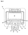
- FIG. 1 shows a casting chamber 12 of a die casting machine 10 in a sectional illustration. It can be seen that the casting chamber 12 has two outlets 16, 18 in the region of a base 24 for the discharge of the liquid metallic die casting material into the casting barrel 20.
- the casting runs 20 are connected to a mold cavity 22 via channels 36.
- an overflow channel 26 is formed on the mold side in the upper area 34 opposite the bottom area 24 and opens into an overflow tank 28.
- Figure 2 shows a side sectional view of the casting chamber 14 of the die casting machine 10. It can be seen that a movable casting piston 14 is arranged within the casting chamber 12, which during the forward movement in the direction of the casting barrel 20 or the mold cavity 22 the casting material 30 via the outlet 16 in the Casting barrel 20 and thus transferred into the mold cavity 22.
- the outlet 16 (like the outlet 18, not shown) is arranged on the mold side in the region of the bottom 24 of the casting chamber 12.
- the overflow channel 26 is arranged on the mold side and is connected to the overflow tank 28. It can be seen that on the low-oxide or oxide-free layer of the casting material 30 there is a lighter, that is to say less dense layer 32 consisting of oxide-containing parts of the casting material.
- the arrangement of the drains 16, 18 in the lower region of the casting chamber 14 and of the overflow channel 26 in the upper region of the casting chamber 14 results in a reliable separation of the layers 30, 32. Only low-oxide or oxide-free casting material is placed in the casting run 20 and thus in the mold cavity 22 30 transferred.
- the casting material 30 consists of a melt of a light metal or light metal alloy, the light metal being in particular aluminum or magnesium.
Landscapes
- Engineering & Computer Science (AREA)
- Mechanical Engineering (AREA)
- Molds, Cores, And Manufacturing Methods Thereof (AREA)
- Casting Devices For Molds (AREA)
- Casting Support Devices, Ladles, And Melt Control Thereby (AREA)
- Filling Of Jars Or Cans And Processes For Cleaning And Sealing Jars (AREA)
Abstract
Description
- Die vorliegende Erfindung betrifft eine Gießkammer einer Druckgießmaschine mit einem innerhalb der Gießkammer beweglichen Gießkolben und mindestens einem Ablauf zum Ablauf des flüssigen metallischen Druckgießmaterials in mindestens einen Gießlauf, wobei der Gießlauf mit einem Formhohlraum in Verbindung steht. Des Weiteren betrifft die Erfindung ein Verfahren zur Formfüllung einer Druckgießmaschine.
- Derartige Gießkammern für Druckgießmaschinen und Verfahren zur Formfüllung einer Druckgießmaschine sind bekannt. Üblicherweise wird bei horizontalen Kaltkammerdruckgießmaschinen das flüssige Metall über einen geeigneten Kanal, nämlich dem Gießlauf im sogenannten Gießamboss, der in ein formenseitiges Ende der Gießkammer eintaucht, in einen sogenannten Anschnitt und anschließend in den Formhohlraum geführt. Der Verbindungskanal zwischen der Gießkammer und dem Gießlauf ist üblicherweise derart angeordnet, dass das flüssige Metall erst bei einem sehr hohen Füllgrad der Gießkammer in den Gießlauf gelangt. Nachteiligerweise entstehen verfahrensbedingt bei der Befüllung der Gießkammer mit flüssigem Metall durch dessen Affinität mit Sauerstoff Oxide, die sich auf der Metalloberfläche beziehungsweise Badoberfläche ansammeln. Durch die relativ hohe Anordnung des Verbindungskanals zum Gießlauf im Gießamboss gelangt der auf der Badoberfläche der Gießkammer stark oxidhaltige Anteil der Schmelze während der Formfüllung direkt in den Formhohlraum des zu gießenden Gussteils. Im resultierenden Gussteil treten die Oxide in der Regel als flächenförmige Störungen im Gefüge auf und beeinflussen nachteiligerweise die mechanischen Eigenschaften der Gussteile.
- Es ist daher Aufgabe der vorliegenden Erfindung eine Gießkammer einer Druckgießmaschine der eingangs genannten Art bereitzustellen, die einen Eintritt von oxidhaltigen Anteilen des Gießmaterials in einen Formhohlraum zuverlässig verhindert.
- Es ist weiterhin Aufgabe der vorliegenden Erfindung ein Verfahren zur Formfüllung einer Druckgießmaschine bereitzustellen, welches einen Eintritt von oxidhaltigen Anteilen des Gießmaterials in einen Formhohlraum zuverlässig verhindert.
- Zur Lösung dieser Aufgaben dient eine gattungsgemäße Gießkammer gemäß den Merkmalen des Hauptanspruchs 1 und ein Verfahren gemäß den Merkmalen des unabhängigen Anspruchs 5.
- Vorteilhafte Ausgestaltungen sind in den jeweiligen Unteransprüchen beschrieben.
- Eine erfindungsgemäße Gießkammer einer Druckgießmaschine mit einem innerhalb der Gießkammer beweglich angeordneten Gießkolben und mindestens einem Ablauf zum Ablaufen des flüssigen metallischen Druckgießmaterials in mindestens einen Gießlauf, wobei der Gießlauf mit einem Formhohlraum in Verbindung steht, weist vorteilhafterweise einen Ablauf auf, der formseitig im Bereich des Bodens der Gießkammer angeordnet ist. Somit wird die Metallzufuhr in den Gießlauf zum Anschnitt des Gussteils am unteren formseitigen Austritt der Schmelze aus der Gießkammer in die Form eingebracht. Dadurch wird vorteilhafterweise erreicht, dass während der Vorwärtsbewegung des Gießkolbens eine Separierung der oxidbehafteten leichteren, und damit oberen Metallschicht nicht in den Bereich des Bodens der Gießkammer angeordneten Ablauf kommt. Nur oxidarmes beziehungsweise oxidfreies Gießmaterial strömt aus dem unteren Bereich der Gießkammer in den Gießlauf und damit in den Formhohlraum. Somit wird der Eintritt von oxidhaltigen Anteilen des Gießmaterials in den Formhohlraum zuverlässig verhindert.
- In einer vorteilhaften Ausgestaltung der Erfindung ist im oberen, dem Bodenbereich gegenüberliegenden Bereich der Gießkammer formseitig mindestens ein Überlaufkanal, der in mindestens einen Überlaufbehälter mündet, ausgebildet. Durch die zusätzliche Anordnung eines oberen formseitigen Austritts der Schmelze aus der Gießkammer erfolgt eine Separierung der oxidhaltigen Anteile über den Überlaufkanal in den Überlaufbehälter und ein Fließen des oxidarmen beziehungsweise oxidfreien Gießmaterials aus dem unteren Bereich der Gießkammer in den Formhohlraum. Durch die Abschöpfung der oxidhaltigen Anteile des Gießmaterials und deren Überführung in den Überlaufbehälter wird wiederum der Eintritt von oxidhaltigen Anteilen des Gießmaterials in den Formhohlraum zuverlässig verhindert.
- In einer weiteren vorteilhaften Ausgestaltung der Erfindung ist das Gießmaterial eine Schmelze eines Leichtmetalls oder einer Leichtmetall-Legierung, wobei das Leichtmetall insbesondere Aluminium oder Magnesium ist.
- Ein erfindungsgemäßes Verfahren zur Formfüllung einer Druckgießmaschine umfasst folgende Schritte: (a) Einfüllen eines flüssigen metallischen Druckgießmaterials in eine Gießkammer und (b) Bewegen eines innerhalb der Gießkammer angeordneten Gießkolbens in Richtung eines Formhohlraums und Überführung des Gießmaterials über mindestens einen Ablauf in mindestens einen Gießlauf, wobei der Gießlauf mit dem Formhohlraum in Verbindung steht und der Ablauf formseitig im Bereich des Bodens der Gießkammer angeordnet ist. Durch die Zufuhr des Gießmaterials in den Gießlauf zum Anschnitt des Gussteils am unteren formseitigen Austritt des Gießmaterials aus der Gießkammer wird zuverlässig der Eintritt von oxidhaltigen Anteilen des Gießmaterials in den Formhohlraum verhindert.
- In einer weiteren vorteilhaften Ausgestaltung des erfindungsgemäßen Verfahrens ist im oberen, dem Bodenbereich gegenüberliegendem Bereich der Gießkammer formseitig mindestens ein Überlaufkanal, der in mindestens einem Überlaufbehälter mündet, ausgebildet. Durch die Ausbildung eines Überlaufkanals und einem Überlaufbehälter erfolgt eine zuverlässige Separierung der oxidbehafteten oberen Gießmaterialschicht in den Überlaufbehälter und ein Überführen des oxidarmen beziehungsweise oxidfreien Gießmaterials aus dem unteren Bereich der Gießkammer in den Formhohlraum. Ein Eindringen des oxidhaltigen Gießmaterials in den Formhohlraum wird somit zuverlässig verhindert.
- In einer weiteren vorteilhaften Ausgestaltung des erfindungsgemäßen Verfahrens ist das Gießmaterial eine Schmelze eines Leichtmetalls oder einer Leichtmetall-Legierung, wobei das Leichtmetall insbesondere Aluminium oder Magnesium ist.
- Weitere Einzelheiten, Merkmale und Vorteile der Erfindung ergeben sich aus dem in den folgenden Zeichnungen dargestellten Ausführungsbeispiel. Es zeigen:
- Figur 1
- eine Schnittdarstellung einer erfindungsgemäßen Gießkammer einer Druckgießmaschine; und
- Figur 2
- eine seitliche Schnittdarstellung der Gießkammer gemäß Figur 1.
- Figur 1 zeigt in einer Schnittdarstellung eine Gießkammer 12 einer Druckgießmaschine 10. Man erkennt, dass die Gießkammer 12 formseitig im Bereich eines Bodens 24 zwei Abläufe 16, 18 zum Ablaufen des flüssigen metallischen Druckgießmaterials in die Gießläufe 20 aufweist. Die Gießläufe 20 stehen über Kanäle 36 mit einem Formhohlraum 22 in Verbindung. Des Weiteren erkennt man, dass im oberen, dem Bodenbereich 24 gegenüberliegendem Bereich 34 formseitig ein Überlaufkanal 26 ausgebildet ist, der in einem Überlaufbehälter 28 mündet.
- Figur 2 zeigt eine seitliche Schnittdarstellung der Gießkammer 14 der Druckgießmaschine 10. Man erkennt, dass innerhalb der Gießkammer 12 ein beweglicher Gießkolben 14 angeordnet ist, der während der Vorwärtsbewegung in Richtung des Gießlaufs 20 beziehungsweise des Formhohlraums 22 das Gießmaterial 30 über den Ablauf 16 in den Gießlauf 20 und damit in den Formhohlraum 22 überführt. Der Ablauf 16 (wie auch der nicht dargestellte Ablauf 18) ist dabei formseitig im Bereich des Bodens 24 der Gießkammer 12 angeordnet. In dem oberen, dem Bodenbereich 24 gegenüberliegendem Bereich 34 ist formseitig der Überlaufkanal 26 angeordnet, der mit dem Überlaufbehälter 28 in Verbindung steht. Man erkennt, dass auf der oxidarmen beziehungsweise oxidfreien Schicht des Gießmaterials 30 eine leichtere, das heißt weniger dichte Schicht 32 bestehend aus oxidhaltigen Anteilen des Gießmaterials aufliegt beziehungsweise aufstimmt. Durch die Anordnung der Abläufe 16, 18 im unteren Bereich der Gießkammer 14 und des Überlaufkanals 26 im oberen Bereich der Gießkammer 14 erfolgt eine zuverlässige Separierung der Schichten 30, 32. In den Gießlauf 20 und damit in den Formhohlraum 22 wird nur oxidarmes beziehungsweise oxidfreies Gießmaterial 30 überführt. Das Gießmaterial 30 besteht dabei aus einer Schmelze eines Leichtmetalls oder Leichtmetall-Legierung, wobei das Leichtmetall insbesondere Aluminium oder Magnesium ist.
Claims (8)
- Gießkammer einer Druckgießmaschine (10) mit einem innerhalb der Gießkammer (12) beweglichen Gießkolben (14) und mindestens einem Ablauf (16, 18) zum Ablauf des flüssigen metallischen Druckgießmaterials (30) in mindestens einen Gießlauf (20), wobei der Gießlauf (20) mit einem Formhohlraum (22) in Verbindung steht,
dadurch gekennzeichnet,
dass der Ablauf (16, 18) formseitig in Bereich des Bodens (24) der Gießkammer (12) angeordnet ist. - Gießkammer nach Anspruch 1,
dadurch gekennzeichnet,
dass im oberen, dem Bodenbereich (24) gegenüberliegendem Bereich (34) formseitig mindestens ein Überlaufkanal (26), der in mindestens einem Überlaufbehälter (28) mündet, ausgebildet ist. - Gießkammer nach Anspruch 1 oder 2,
dadurch gekennzeichnet,
dass das Gießmaterial (30) eine Schmelze eines Leichtmetalls oder einer Leichtmetall-Legierung ist. - Gießkammer nach Anspruch 3,
dadurch gekennzeichnet,
dass das Leichtmetall Aluminium oder Magnesium ist. - Verfahren zur Formfüllung einer Druckgießmaschine (10), wobei das Verfahren folgende Schritte umfasst:a) Einfüllen eines flüssigen metallischen Druckgießmaterials in eine Gießkammer (12);b) Bewegen eines innerhalb der Gießkammer (12) angeordneten Gießkolbens (14) in Richtung eines Formhohlraums (22) und Überführung des Gießmaterials (30) über mindestens einen Ablauf (16, 18) in mindestens einen Gießlauf (20), wobei der Gießlauf (20) mit dem Formhohlraum (22) in Verbindung steht und der Ablauf (16, 18) formseitig in Bereich des Bodens (24) der Gießkammer (12) angeordnet ist.
- Verfahren nach Anspruch 5,
dadurch gekennzeichnet,
dass im oberen, dem Bodenbereich (24) gegenüberliegendem Bereich (34) formseitig mindestens ein Überlaufkanal (26), der in mindestens einem Überlaufbehälter (28) mündet, ausgebildet ist. - Verfahren nach Anspruch 5 oder 6,
dadurch gekennzeichnet,
dass das Gießmaterial (30) eine Schmelze eines Leichtmetalls oder einer Leichtmetall-Legierung ist. - Verfahren nach Anspruch 7,
dadurch gekennzeichnet,
dass das Leichtmetall Aluminium oder Magnesium ist.
Priority Applications (3)
| Application Number | Priority Date | Filing Date | Title |
|---|---|---|---|
| DE50301106T DE50301106D1 (de) | 2003-06-23 | 2003-06-23 | Giesskammer einer Druckgiessmaschine und Verfahren zur Formfüllung einer Druckgiessmaschine |
| EP03014120A EP1491276B1 (de) | 2003-06-23 | 2003-06-23 | Giesskammer einer Druckgiessmaschine und Verfahren zur Formfüllung einer Druckgiessmaschine |
| AT03014120T ATE303216T1 (de) | 2003-06-23 | 2003-06-23 | Giesskammer einer druckgiessmaschine und verfahren zur formfüllung einer druckgiessmaschine |
Applications Claiming Priority (1)
| Application Number | Priority Date | Filing Date | Title |
|---|---|---|---|
| EP03014120A EP1491276B1 (de) | 2003-06-23 | 2003-06-23 | Giesskammer einer Druckgiessmaschine und Verfahren zur Formfüllung einer Druckgiessmaschine |
Publications (2)
| Publication Number | Publication Date |
|---|---|
| EP1491276A1 true EP1491276A1 (de) | 2004-12-29 |
| EP1491276B1 EP1491276B1 (de) | 2005-08-31 |
Family
ID=33395850
Family Applications (1)
| Application Number | Title | Priority Date | Filing Date |
|---|---|---|---|
| EP03014120A Expired - Lifetime EP1491276B1 (de) | 2003-06-23 | 2003-06-23 | Giesskammer einer Druckgiessmaschine und Verfahren zur Formfüllung einer Druckgiessmaschine |
Country Status (3)
| Country | Link |
|---|---|
| EP (1) | EP1491276B1 (de) |
| AT (1) | ATE303216T1 (de) |
| DE (1) | DE50301106D1 (de) |
Citations (5)
| Publication number | Priority date | Publication date | Assignee | Title |
|---|---|---|---|---|
| US2244816A (en) * | 1939-09-27 | 1941-06-10 | Aluminum Co Of America | Die casting apparatus |
| DE19606160A1 (de) * | 1996-02-20 | 1997-08-21 | Bayerische Motoren Werke Ag | Kaltkammer-Druckgießmaschine mit einer horizontalen oder schrägen Füllkammer |
| EP0940206A1 (de) * | 1998-03-04 | 1999-09-08 | Alusuisse Technology & Management AG | Oxidabscheider |
| DE10122028A1 (de) * | 2001-05-07 | 2002-11-14 | Buehler Druckguss Ag Uzwil | Verfahren zum Druckgiessen und Druckgiessmaschine |
| DE10144945A1 (de) * | 2001-09-12 | 2003-04-10 | Alcan Bdw Gmbh & Co Kg | Verfahren zum Steuern eines Vakuumventils einer Vakuumdruckgießvorrichtung sowie Vakuumdruckgießvorrichtung |
-
2003
- 2003-06-23 AT AT03014120T patent/ATE303216T1/de not_active IP Right Cessation
- 2003-06-23 EP EP03014120A patent/EP1491276B1/de not_active Expired - Lifetime
- 2003-06-23 DE DE50301106T patent/DE50301106D1/de not_active Expired - Fee Related
Patent Citations (5)
| Publication number | Priority date | Publication date | Assignee | Title |
|---|---|---|---|---|
| US2244816A (en) * | 1939-09-27 | 1941-06-10 | Aluminum Co Of America | Die casting apparatus |
| DE19606160A1 (de) * | 1996-02-20 | 1997-08-21 | Bayerische Motoren Werke Ag | Kaltkammer-Druckgießmaschine mit einer horizontalen oder schrägen Füllkammer |
| EP0940206A1 (de) * | 1998-03-04 | 1999-09-08 | Alusuisse Technology & Management AG | Oxidabscheider |
| DE10122028A1 (de) * | 2001-05-07 | 2002-11-14 | Buehler Druckguss Ag Uzwil | Verfahren zum Druckgiessen und Druckgiessmaschine |
| DE10144945A1 (de) * | 2001-09-12 | 2003-04-10 | Alcan Bdw Gmbh & Co Kg | Verfahren zum Steuern eines Vakuumventils einer Vakuumdruckgießvorrichtung sowie Vakuumdruckgießvorrichtung |
Also Published As
| Publication number | Publication date |
|---|---|
| DE50301106D1 (de) | 2005-10-06 |
| EP1491276B1 (de) | 2005-08-31 |
| ATE303216T1 (de) | 2005-09-15 |
Similar Documents
| Publication | Publication Date | Title |
|---|---|---|
| DE3518635A1 (de) | Druckgussverfahren und -vorrichtung | |
| DE4142447A1 (de) | Tauchgiessrohr - duennbramme | |
| DE2902096C2 (de) | ||
| EP1929146B8 (de) | Verfahren zur herstellung eines kolbens für einen verbrennungsmotor sowie danach hergestellter kolben | |
| CH639881A5 (de) | Verfahren zum aendern eines strangquerschnittformates und kokille zur durchfuehrung des verfahrens. | |
| DE3605529C3 (de) | Druckgießverfahren und Druckgießmaschine | |
| DE102006058142B4 (de) | Verfahren und Vorrichtung zum Kippgießen von Bauteilen aus Leichtmetall | |
| DE2606370A1 (de) | Giessverfahren und giessform zu seiner durchfuehrung | |
| DE2250780A1 (de) | Verfahren und vorrichtung zum niederdruckgiessen | |
| DE4315709C2 (de) | Schiebeausguß für ein Stahlschmelze-Aufnahmegefäß | |
| DE102009026450B4 (de) | Gießvorrichtung und -verfahren, insbesondere für Kolben von Verbrennungsmotoren | |
| EP1491276B1 (de) | Giesskammer einer Druckgiessmaschine und Verfahren zur Formfüllung einer Druckgiessmaschine | |
| DE19807623A1 (de) | Niederdruck-Gießverfahren für Leichtmetalle, insbesondere Aluminium | |
| DE19803866A1 (de) | Gießform und Verfahren zum Herstellen von Gußstücken | |
| DE2620073C2 (de) | ||
| DE60115862T2 (de) | Geschlitztes feuerfestes bauteil zum metallurgischen giessen, anordnung von feuerfesten bauteile und giessvorrichtung | |
| DE2330053B2 (de) | Sicherheitsvorrichtung bei Strangdurchbrüchen an einer Anlage zum StahlstranggieBen | |
| CH671533A5 (de) | ||
| DE3426169C2 (de) | Verfahren und Horizontalstranggießkokille zum Horizontalstranggießen von Metall, insbes. von Stahl, zu dünnen und breiten Strängen | |
| EP3511090A1 (de) | Kaltkammerdruckgiessverfahren und kaltkammerdruckgiessmaschine | |
| DE1758761A1 (de) | Giessverfahren | |
| DE69401773T2 (de) | Giessrohr | |
| DE4007647C2 (de) | Verfahren zur Herstellung einer Kokille für das Stranggießen von Stahl | |
| DE60301056T2 (de) | System zum Abgiessen vom Metallschmelze | |
| EP0070913B1 (de) | Gefäss zur Behandlung von schmelzflüssigen Metallen |
Legal Events
| Date | Code | Title | Description |
|---|---|---|---|
| PUAI | Public reference made under article 153(3) epc to a published international application that has entered the european phase |
Free format text: ORIGINAL CODE: 0009012 |
|
| 17P | Request for examination filed |
Effective date: 20040402 |
|
| AK | Designated contracting states |
Kind code of ref document: A1 Designated state(s): AT BE BG CH CY CZ DE DK EE ES FI FR GB GR HU IE IT LI LU MC NL PT RO SE SI SK TR |
|
| AX | Request for extension of the european patent |
Extension state: AL LT LV MK |
|
| GRAP | Despatch of communication of intention to grant a patent |
Free format text: ORIGINAL CODE: EPIDOSNIGR1 |
|
| GRAS | Grant fee paid |
Free format text: ORIGINAL CODE: EPIDOSNIGR3 |
|
| GRAA | (expected) grant |
Free format text: ORIGINAL CODE: 0009210 |
|
| AK | Designated contracting states |
Kind code of ref document: B1 Designated state(s): AT BE BG CH CY CZ DE DK EE ES FI FR GB GR HU IE IT LI LU MC NL PT RO SE SI SK TR |
|
| PG25 | Lapsed in a contracting state [announced via postgrant information from national office to epo] |
Ref country code: GB Free format text: LAPSE BECAUSE OF FAILURE TO SUBMIT A TRANSLATION OF THE DESCRIPTION OR TO PAY THE FEE WITHIN THE PRESCRIBED TIME-LIMIT Effective date: 20050831 Ref country code: FI Free format text: LAPSE BECAUSE OF FAILURE TO SUBMIT A TRANSLATION OF THE DESCRIPTION OR TO PAY THE FEE WITHIN THE PRESCRIBED TIME-LIMIT Effective date: 20050831 Ref country code: IE Free format text: LAPSE BECAUSE OF FAILURE TO SUBMIT A TRANSLATION OF THE DESCRIPTION OR TO PAY THE FEE WITHIN THE PRESCRIBED TIME-LIMIT Effective date: 20050831 Ref country code: CZ Free format text: LAPSE BECAUSE OF FAILURE TO SUBMIT A TRANSLATION OF THE DESCRIPTION OR TO PAY THE FEE WITHIN THE PRESCRIBED TIME-LIMIT Effective date: 20050831 Ref country code: SK Free format text: LAPSE BECAUSE OF FAILURE TO SUBMIT A TRANSLATION OF THE DESCRIPTION OR TO PAY THE FEE WITHIN THE PRESCRIBED TIME-LIMIT Effective date: 20050831 Ref country code: SI Free format text: LAPSE BECAUSE OF FAILURE TO SUBMIT A TRANSLATION OF THE DESCRIPTION OR TO PAY THE FEE WITHIN THE PRESCRIBED TIME-LIMIT Effective date: 20050831 Ref country code: RO Free format text: LAPSE BECAUSE OF FAILURE TO SUBMIT A TRANSLATION OF THE DESCRIPTION OR TO PAY THE FEE WITHIN THE PRESCRIBED TIME-LIMIT Effective date: 20050831 |
|
| REG | Reference to a national code |
Ref country code: GB Ref legal event code: FG4D Free format text: NOT ENGLISH Ref country code: CH Ref legal event code: EP |
|
| AKX | Designation fees paid |
Designated state(s): AT BE BG CH CY CZ DE DK EE ES FI FR GB GR HU IE IT LI LU MC NL PT RO SE SI SK TR |
|
| REG | Reference to a national code |
Ref country code: IE Ref legal event code: FG4D Free format text: LANGUAGE OF EP DOCUMENT: GERMAN |
|
| REF | Corresponds to: |
Ref document number: 50301106 Country of ref document: DE Date of ref document: 20051006 Kind code of ref document: P |
|
| PG25 | Lapsed in a contracting state [announced via postgrant information from national office to epo] |
Ref country code: GR Free format text: LAPSE BECAUSE OF FAILURE TO SUBMIT A TRANSLATION OF THE DESCRIPTION OR TO PAY THE FEE WITHIN THE PRESCRIBED TIME-LIMIT Effective date: 20051130 Ref country code: DK Free format text: LAPSE BECAUSE OF FAILURE TO SUBMIT A TRANSLATION OF THE DESCRIPTION OR TO PAY THE FEE WITHIN THE PRESCRIBED TIME-LIMIT Effective date: 20051130 Ref country code: BG Free format text: LAPSE BECAUSE OF FAILURE TO SUBMIT A TRANSLATION OF THE DESCRIPTION OR TO PAY THE FEE WITHIN THE PRESCRIBED TIME-LIMIT Effective date: 20051130 Ref country code: SE Free format text: LAPSE BECAUSE OF FAILURE TO SUBMIT A TRANSLATION OF THE DESCRIPTION OR TO PAY THE FEE WITHIN THE PRESCRIBED TIME-LIMIT Effective date: 20051130 |
|
| PG25 | Lapsed in a contracting state [announced via postgrant information from national office to epo] |
Ref country code: ES Free format text: LAPSE BECAUSE OF FAILURE TO SUBMIT A TRANSLATION OF THE DESCRIPTION OR TO PAY THE FEE WITHIN THE PRESCRIBED TIME-LIMIT Effective date: 20051212 |
|
| PG25 | Lapsed in a contracting state [announced via postgrant information from national office to epo] |
Ref country code: PT Free format text: LAPSE BECAUSE OF FAILURE TO SUBMIT A TRANSLATION OF THE DESCRIPTION OR TO PAY THE FEE WITHIN THE PRESCRIBED TIME-LIMIT Effective date: 20060223 |
|
| REG | Reference to a national code |
Ref country code: CH Ref legal event code: NV Representative=s name: BREITER + PARTNER AG PATENT - UND MARKENBUERO |
|
| PG25 | Lapsed in a contracting state [announced via postgrant information from national office to epo] |
Ref country code: HU Free format text: LAPSE BECAUSE OF FAILURE TO SUBMIT A TRANSLATION OF THE DESCRIPTION OR TO PAY THE FEE WITHIN THE PRESCRIBED TIME-LIMIT Effective date: 20060301 |
|
| REG | Reference to a national code |
Ref country code: IE Ref legal event code: FD4D |
|
| GBV | Gb: ep patent (uk) treated as always having been void in accordance with gb section 77(7)/1977 [no translation filed] |
Effective date: 20050831 |
|
| ET | Fr: translation filed | ||
| PGFP | Annual fee paid to national office [announced via postgrant information from national office to epo] |
Ref country code: FR Payment date: 20060621 Year of fee payment: 4 |
|
| PGFP | Annual fee paid to national office [announced via postgrant information from national office to epo] |
Ref country code: AT Payment date: 20060626 Year of fee payment: 4 |
|
| PG25 | Lapsed in a contracting state [announced via postgrant information from national office to epo] |
Ref country code: MC Free format text: LAPSE BECAUSE OF NON-PAYMENT OF DUE FEES Effective date: 20060630 Ref country code: BE Free format text: LAPSE BECAUSE OF NON-PAYMENT OF DUE FEES Effective date: 20060630 |
|
| PGFP | Annual fee paid to national office [announced via postgrant information from national office to epo] |
Ref country code: IT Payment date: 20060630 Year of fee payment: 4 |
|
| PLBE | No opposition filed within time limit |
Free format text: ORIGINAL CODE: 0009261 |
|
| STAA | Information on the status of an ep patent application or granted ep patent |
Free format text: STATUS: NO OPPOSITION FILED WITHIN TIME LIMIT |
|
| 26N | No opposition filed |
Effective date: 20060601 |
|
| PGFP | Annual fee paid to national office [announced via postgrant information from national office to epo] |
Ref country code: DE Payment date: 20060831 Year of fee payment: 4 |
|
| REG | Reference to a national code |
Ref country code: CH Ref legal event code: PFA Owner name: ALCAN BDW GMBH & CO. KG Free format text: ALCAN BDW GMBH & CO. KG#IM WIEGENFELD 10#85570 MARKT SCHWABEN (DE) -TRANSFER TO- ALCAN BDW GMBH & CO. KG#IM WIEGENFELD 10#85570 MARKT SCHWABEN (DE) |
|
| BERE | Be: lapsed |
Owner name: *ALCAN BDW G.M.B.H. & CO. K.G. Effective date: 20060630 |
|
| REG | Reference to a national code |
Ref country code: CH Ref legal event code: PL |
|
| PG25 | Lapsed in a contracting state [announced via postgrant information from national office to epo] |
Ref country code: AT Free format text: LAPSE BECAUSE OF NON-PAYMENT OF DUE FEES Effective date: 20070623 |
|
| NLV4 | Nl: lapsed or anulled due to non-payment of the annual fee |
Effective date: 20080101 |
|
| REG | Reference to a national code |
Ref country code: FR Ref legal event code: ST Effective date: 20080229 |
|
| PG25 | Lapsed in a contracting state [announced via postgrant information from national office to epo] |
Ref country code: CH Free format text: LAPSE BECAUSE OF NON-PAYMENT OF DUE FEES Effective date: 20070630 Ref country code: LI Free format text: LAPSE BECAUSE OF NON-PAYMENT OF DUE FEES Effective date: 20070630 Ref country code: DE Free format text: LAPSE BECAUSE OF NON-PAYMENT OF DUE FEES Effective date: 20080101 Ref country code: NL Free format text: LAPSE BECAUSE OF NON-PAYMENT OF DUE FEES Effective date: 20080101 |
|
| PG25 | Lapsed in a contracting state [announced via postgrant information from national office to epo] |
Ref country code: EE Free format text: LAPSE BECAUSE OF FAILURE TO SUBMIT A TRANSLATION OF THE DESCRIPTION OR TO PAY THE FEE WITHIN THE PRESCRIBED TIME-LIMIT Effective date: 20050831 |
|
| PG25 | Lapsed in a contracting state [announced via postgrant information from national office to epo] |
Ref country code: LU Free format text: LAPSE BECAUSE OF NON-PAYMENT OF DUE FEES Effective date: 20060623 Ref country code: TR Free format text: LAPSE BECAUSE OF FAILURE TO SUBMIT A TRANSLATION OF THE DESCRIPTION OR TO PAY THE FEE WITHIN THE PRESCRIBED TIME-LIMIT Effective date: 20050831 |
|
| PG25 | Lapsed in a contracting state [announced via postgrant information from national office to epo] |
Ref country code: FR Free format text: LAPSE BECAUSE OF NON-PAYMENT OF DUE FEES Effective date: 20070702 |
|
| PG25 | Lapsed in a contracting state [announced via postgrant information from national office to epo] |
Ref country code: CY Free format text: LAPSE BECAUSE OF FAILURE TO SUBMIT A TRANSLATION OF THE DESCRIPTION OR TO PAY THE FEE WITHIN THE PRESCRIBED TIME-LIMIT Effective date: 20050831 |
|
| PG25 | Lapsed in a contracting state [announced via postgrant information from national office to epo] |
Ref country code: IT Free format text: LAPSE BECAUSE OF NON-PAYMENT OF DUE FEES Effective date: 20070623 |