EP1491321A2 - Procédé de fabrication des bouteilles bicomposantes et installation pour la mise en oeuvre d'un tel procédé - Google Patents
Procédé de fabrication des bouteilles bicomposantes et installation pour la mise en oeuvre d'un tel procédé Download PDFInfo
- Publication number
- EP1491321A2 EP1491321A2 EP04076773A EP04076773A EP1491321A2 EP 1491321 A2 EP1491321 A2 EP 1491321A2 EP 04076773 A EP04076773 A EP 04076773A EP 04076773 A EP04076773 A EP 04076773A EP 1491321 A2 EP1491321 A2 EP 1491321A2
- Authority
- EP
- European Patent Office
- Prior art keywords
- insert
- mould
- tube
- plant
- various polymer
- Prior art date
- Legal status (The legal status is an assumption and is not a legal conclusion. Google has not performed a legal analysis and makes no representation as to the accuracy of the status listed.)
- Withdrawn
Links
Images




Classifications
-
- B—PERFORMING OPERATIONS; TRANSPORTING
- B29—WORKING OF PLASTICS; WORKING OF SUBSTANCES IN A PLASTIC STATE IN GENERAL
- B29C—SHAPING OR JOINING OF PLASTICS; SHAPING OF MATERIAL IN A PLASTIC STATE, NOT OTHERWISE PROVIDED FOR; AFTER-TREATMENT OF THE SHAPED PRODUCTS, e.g. REPAIRING
- B29C49/00—Blow-moulding, i.e. blowing a preform or parison to a desired shape within a mould; Apparatus therefor
- B29C49/20—Blow-moulding, i.e. blowing a preform or parison to a desired shape within a mould; Apparatus therefor of articles having inserts or reinforcements ; Handling of inserts or reinforcements
-
- B—PERFORMING OPERATIONS; TRANSPORTING
- B29—WORKING OF PLASTICS; WORKING OF SUBSTANCES IN A PLASTIC STATE IN GENERAL
- B29C—SHAPING OR JOINING OF PLASTICS; SHAPING OF MATERIAL IN A PLASTIC STATE, NOT OTHERWISE PROVIDED FOR; AFTER-TREATMENT OF THE SHAPED PRODUCTS, e.g. REPAIRING
- B29C45/00—Injection moulding, i.e. forcing the required volume of moulding material through a nozzle into a closed mould; Apparatus therefor
- B29C45/17—Component parts, details or accessories; Auxiliary operations
- B29C45/40—Removing or ejecting moulded articles
- B29C45/42—Removing or ejecting moulded articles using means movable from outside the mould between mould parts, e.g. robots
-
- B—PERFORMING OPERATIONS; TRANSPORTING
- B29—WORKING OF PLASTICS; WORKING OF SUBSTANCES IN A PLASTIC STATE IN GENERAL
- B29C—SHAPING OR JOINING OF PLASTICS; SHAPING OF MATERIAL IN A PLASTIC STATE, NOT OTHERWISE PROVIDED FOR; AFTER-TREATMENT OF THE SHAPED PRODUCTS, e.g. REPAIRING
- B29C49/00—Blow-moulding, i.e. blowing a preform or parison to a desired shape within a mould; Apparatus therefor
- B29C49/0005—Blow-moulding, i.e. blowing a preform or parison to a desired shape within a mould; Apparatus therefor characterised by the material
-
- B—PERFORMING OPERATIONS; TRANSPORTING
- B29—WORKING OF PLASTICS; WORKING OF SUBSTANCES IN A PLASTIC STATE IN GENERAL
- B29K—INDEXING SCHEME ASSOCIATED WITH SUBCLASSES B29B, B29C OR B29D, RELATING TO MOULDING MATERIALS OR TO MATERIALS FOR MOULDS, REINFORCEMENTS, FILLERS OR PREFORMED PARTS, e.g. INSERTS
- B29K2021/00—Use of unspecified rubbers as moulding material
-
- B—PERFORMING OPERATIONS; TRANSPORTING
- B29—WORKING OF PLASTICS; WORKING OF SUBSTANCES IN A PLASTIC STATE IN GENERAL
- B29K—INDEXING SCHEME ASSOCIATED WITH SUBCLASSES B29B, B29C OR B29D, RELATING TO MOULDING MATERIALS OR TO MATERIALS FOR MOULDS, REINFORCEMENTS, FILLERS OR PREFORMED PARTS, e.g. INSERTS
- B29K2023/00—Use of polyalkenes or derivatives thereof as moulding material
-
- B—PERFORMING OPERATIONS; TRANSPORTING
- B29—WORKING OF PLASTICS; WORKING OF SUBSTANCES IN A PLASTIC STATE IN GENERAL
- B29K—INDEXING SCHEME ASSOCIATED WITH SUBCLASSES B29B, B29C OR B29D, RELATING TO MOULDING MATERIALS OR TO MATERIALS FOR MOULDS, REINFORCEMENTS, FILLERS OR PREFORMED PARTS, e.g. INSERTS
- B29K2221/00—Use of unspecified rubbers as reinforcement
- B29K2221/003—Thermoplastic elastomers
-
- B—PERFORMING OPERATIONS; TRANSPORTING
- B29—WORKING OF PLASTICS; WORKING OF SUBSTANCES IN A PLASTIC STATE IN GENERAL
- B29K—INDEXING SCHEME ASSOCIATED WITH SUBCLASSES B29B, B29C OR B29D, RELATING TO MOULDING MATERIALS OR TO MATERIALS FOR MOULDS, REINFORCEMENTS, FILLERS OR PREFORMED PARTS, e.g. INSERTS
- B29K2623/00—Use of polyalkenes or derivatives thereof for preformed parts, e.g. for inserts
Definitions
- the present invention relates to the manufacture of plastic bottles for containing miscellaneous products, such as cosmetics, detergent, pharmaceutical and para-pharmaceutical products, and generally all products dispensable in the form of creams, liquids or fluid pastes.
- miscellaneous products such as cosmetics, detergent, pharmaceutical and para-pharmaceutical products
- Such bottles of the state of the art present an outer surface intended to receive labels, or inscriptions and decorations directly printed on the bottle, and are generally manufactured starting from an extruded tube subsequently treated by a blow-moulding process within a suitable mould.
- the need to apply generally flat labels to the bottle or to create inscriptions or decorations directly on the bottle means that at least a portion of the bottle must be cylindrical, or have a curvature suitable for label application or for decoration.
- Said labels and decorations have only a decorative and communicative function, and in no way confer functional characteristics to the product. Moreover, when wetted, the material used for bottle manufacture becomes slippery and difficult to retain with the hands; this makes such bottles very uncomfortable to use if containing for example soapy liquids, and are used in showers or bath tubs.
- the object of the present patent is to provide a process enabling said bottles to be manufactured without any limitation with regard to shape and the associated functional characteristics.
- the process of the invention provides for creating a tube by extruding a synthetic resin chosen from the following:
- HDPE high density polyethylene
- the extrusion is preferably carried out in special machines of the type comprising an extrusion feeder screw with a distribution head for the extruded tube, usually used for manufacturing hollow bodies of thermoplastic materials in one or more layers.
- the extrusion temperature is between 170°C and 220°C.
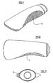
- an insert is formed of material having particular characteristics different from those of the bottle constituent material.
- Said characteristics can be of tactile type, for example the insert can be soft to the touch and/or anti-slip, or of aesthetic type.
- the insert material is preferably chosen from the following suitable materials:
- Thermoplastic elastomeric resins can also be advantageously used, such as SANTOPRENE, manufactured by Monsanto, or similar materials of miscellaneous production and origin.
- non-plastic materials such as glass and light metals can also be used.
- the insert manufactured separately from the tube in a different plant, is withdrawn from the injection mould and transferred into the blow mould by robotized automatic systems and suitable gripping systems.
- Said automatic systems can also be used to insert inserts of different material into the mould.
- More than one insert can be inserted into the same mould.
- a forming plant will now be described by way of example, comprising an injection device with a single impression for moulding one insert at a time, however in reality a mould with several impressions is used.
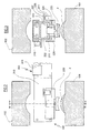
- Figure 1 shows two parts 101 and 102 of an injection mould 100 for forming an insert 3 which on opening the mould remains adhering to its convex part 1a.
- Withdrawal means 200 for the moulded insert are positioned to the side of the injection machine.
- Said means comprise a base portion 201 which slidably supports a beam 210 on which a carriage 220 slides.
- the beam 210 (see Figure 3) is an asymmetric double T beam, the major flanges of which support the slidable carriage 220, which has a shell 221 of C cross-section.
- the shell 221 comprises four idle rollers 222 arranged to slide in four guides 211 provided in the beam flanges.
- a single acting cylinder-piston unit 224 the piston rod of which passes through a hole in the shell and carries a profiled implement 225 for pneumatically receiving and retaining the insert 3.
- an electric gearmotor 226 operating a friction wheel 227 which slides along the beam 210 and drags the carriage into two positions at the ends of the beam 210.
- the base 201 (see Figure 5) comprises a vertical plate 202 carrying four idle rollers 203 which slide in guides 212 provided in the minor flanges of the beam 210.
- the plate 202 carries an electric motor 205 of controlled advancement with, keyed onto its shaft, the friction wheel 206 which slides in contact with the lower flange of the beam 210 to drive the beam 210 with a controlled to-and-fro movement.
- the extent of the movements of the beam 210 is such as to bring its left end, with reference to the figures, into a first position between the parts 101 and 102 of the mould 100, and into a second position external to the mould, to enable it to be closed.
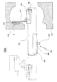
- the transfer means 300 comprise a base portion 301 slidably supporting a beam 310 on which a carriage 320 slides.
- the beam 310 (see Figure 7) is an asymmetric double T beam, the major flanges of which support a slidable carriage 320 having a shell 321 of welded sheet metal.
- the shell 321 comprises four idle rollers 322 which slide in four guides 323 provided in the flanges of the beam 310.
- a pneumatic single acting cylinder-piston unit 342 the piston rod of which is coupled to a rack portion 325, which is parallel to the axis of the cylinder-piston unit and engages an idly mounted gearwheel 326.
- the gearwheel 326 carries a tangential arm 327, on the end of which there is an implement 328 for collecting and pneumatically retaining the insert 3.
- an electric gearmotor 329 operating a friction wheel 330 which slides along the beam 310 and drags the carriage 320 into two positions at the ends of the beam 310.
- the base 301 (see Figure 7) comprises a vertical plate 302 carrying four idle rollers 303 which slide in guides 312 provided in the minor flanges of the beam 310.
- the plate 302 carries an electric motor 305 of controlled advancement with, keyed onto its shaft, the friction wheel 306 which slides in contact with the lower flange of the beam 310 to drive the beam 310 with a controlled to-and-fro movement.
- the extent of the movements of the beam 310 is such as to bring its right end, with reference to the figures, into a first position between the parts 401 and 402 of the blow mould 400, and into a second position external to the mould.
- the line operates in the following manner.
- the beam 210 moves into the position shown in Figure 2, and the carriage 220 moves to the left end, with reference to the figures, of the beam 210.
- the cylinder-piston unit 224 is operated to bring the implement into contact with the insert, which remains adhering thereto by usual suction means, not shown.
- the beam 310 and carriage 320 then move completely towards the right in the figures, to bring this latter into the position shown in Figure 6, where the cylinder-piston unit 324 is operated to rotate the arm 326 until the insert 3 is deposited in the blow mould.
- the inserts can be also deposited on the joining or closure line of the two mould halves.
- a blast of compressed air is fed through suitable nozzles to deform the extruded plastic tube by swelling, so that it is brought to adhere with the walls of the mould, hence incorporating the inserts which have been deposited in the mould, by adhering to their inner sides and filling the voids, and also creating those protuberances and relief decorations which give the bottle particular functional, aesthetic and tactile characteristics.
- said process can start with the withdrawal of the inserts from appropriate containers or stores, and then proceed in the described manner.
Landscapes
- Engineering & Computer Science (AREA)
- Manufacturing & Machinery (AREA)
- Mechanical Engineering (AREA)
- Robotics (AREA)
- Blow-Moulding Or Thermoforming Of Plastics Or The Like (AREA)
Applications Claiming Priority (2)
| Application Number | Priority Date | Filing Date | Title |
|---|---|---|---|
| IT000060A ITRE20030060A1 (it) | 2003-06-24 | 2003-06-24 | Processo di fabbricazione di flaconi ad almeno due |
| ITRE20030060 | 2003-06-24 |
Publications (2)
| Publication Number | Publication Date |
|---|---|
| EP1491321A2 true EP1491321A2 (fr) | 2004-12-29 |
| EP1491321A3 EP1491321A3 (fr) | 2005-01-12 |
Family
ID=33398070
Family Applications (1)
| Application Number | Title | Priority Date | Filing Date |
|---|---|---|---|
| EP04076773A Withdrawn EP1491321A3 (fr) | 2003-06-24 | 2004-06-16 | Procédé de fabrication des bouteilles bicomposantes et installation pour la mise en oeuvre d'un tel procédé |
Country Status (2)
| Country | Link |
|---|---|
| EP (1) | EP1491321A3 (fr) |
| IT (1) | ITRE20030060A1 (fr) |
Family Cites Families (11)
| Publication number | Priority date | Publication date | Assignee | Title |
|---|---|---|---|---|
| JPS6311317A (ja) * | 1986-07-03 | 1988-01-18 | Sekisui Chem Co Ltd | 成形装置 |
| CA1340219C (fr) * | 1988-04-06 | 1998-12-15 | Tadahiko Katsura | Contenant marque et procede de fabrication |
| US5234328A (en) * | 1991-10-29 | 1993-08-10 | Cbw Automation, Inc. | Retrieval system for removing articles formed by a manufacturing apparatus |
| US5266149A (en) * | 1992-01-17 | 1993-11-30 | Continental Pet Technologies, Inc. | In-mold labelling system |
| DE29601739U1 (de) * | 1996-02-01 | 1996-06-20 | Leiritz, Otto, 91788 Pappenheim | Kunststoffentnahmesystem |
| JP3242033B2 (ja) * | 1997-07-15 | 2001-12-25 | アスモ株式会社 | 樹脂製容器の製造方法 |
| US6049945A (en) * | 1998-12-17 | 2000-04-18 | Graham Packaging Company L.P. | Stackable ergonomic handle |
| US6464922B1 (en) * | 1999-12-10 | 2002-10-15 | Autotec, Inc. | Insertion device for plastic molding |
| US20020086085A1 (en) * | 2001-01-04 | 2002-07-04 | Kazutoshi Takayama | Robot for production machine |
| US6730257B2 (en) * | 2001-02-12 | 2004-05-04 | Owens-Brockway Plastic Products Inc. | Shuttle-type blow molding method and apparatus |
| FR2821583A1 (fr) * | 2001-03-01 | 2002-09-06 | Qualiform | Procede de fabrication par la technique du soufflage d'un recipient en matiere plastique et plus particulierement d'un flacon destine notamment au domaine de la cosmetique |
-
2003
- 2003-06-24 IT IT000060A patent/ITRE20030060A1/it unknown
-
2004
- 2004-06-16 EP EP04076773A patent/EP1491321A3/fr not_active Withdrawn
Also Published As
| Publication number | Publication date |
|---|---|
| EP1491321A3 (fr) | 2005-01-12 |
| ITRE20030060A1 (it) | 2004-12-25 |
Similar Documents
| Publication | Publication Date | Title |
|---|---|---|
| US4708630A (en) | Apparatus for labeling blow-molded articles by placing label directly on the parison | |
| US5503885A (en) | Article with position-defining structure and method and apparatus for making and processing same | |
| CZ9700016A3 (cs) | Vícevrstvý předlisek, způsob tváření předlisku a vícevrstvá nádoba, zhotovená z předlisku | |
| US4605462A (en) | Method of attaching a sheetlike object, e.g., a label, to a hollow body of plastics | |
| US20070190275A1 (en) | Method for the production of a flexible tube | |
| US3259942A (en) | Method and apparatus for the manufacture of containers | |
| CN102161232A (zh) | 贴标取瓶双功能机械手 | |
| PL354722A1 (en) | Releasing undercut moulded containers after a thermoforming process | |
| JP3138248B2 (ja) | 可撓性チューブ及びその製造方法 | |
| EP3917752B1 (fr) | Système et procédé d'étiquetage dans le moule | |
| EP0329888B1 (fr) | Application d'étiquettes sur des objets moulés par soufflage | |
| EP2830854B1 (fr) | Procédé et dispositif pour fabrication des corps creux | |
| EP0892711B1 (fr) | Procede de refaconnage de materiaux plastiques decores | |
| JP6595361B2 (ja) | ブロー成形装置およびブロー成形方法 | |
| EP1491321A2 (fr) | Procédé de fabrication des bouteilles bicomposantes et installation pour la mise en oeuvre d'un tel procédé | |
| AU645428B2 (en) | Label transfer mechanism for blow molding machinery | |
| CN201659689U (zh) | 一种贴标取瓶双功能机械手 | |
| JP6533428B2 (ja) | ブロー成形装置およびブロー成形方法 | |
| US2954588A (en) | Method of forming hollow plastic articles | |
| US5695792A (en) | Blow molding machine for making hollow plastic articles | |
| CN113370500A (zh) | 一种塑料容器成型装置 | |
| EP3870424B1 (fr) | Systeme de fabrication d'un récipient thermoplastique par traction sur un tube | |
| JP2019151123A (ja) | ブロー成形法により製造されたプラスチックボトル | |
| CN109910270B (zh) | 模具、成形站、成形轮、成形机、容器制造方法及此容器 | |
| EP0688658A2 (fr) | Procédé et dispositif pour la fabrication de bouteilles plates |
Legal Events
| Date | Code | Title | Description |
|---|---|---|---|
| PUAI | Public reference made under article 153(3) epc to a published international application that has entered the european phase |
Free format text: ORIGINAL CODE: 0009012 |
|
| PUAL | Search report despatched |
Free format text: ORIGINAL CODE: 0009013 |
|
| AK | Designated contracting states |
Kind code of ref document: A2 Designated state(s): AT BE BG CH CY CZ DE DK EE ES FI FR GB GR HU IE IT LI LU MC NL PL PT RO SE SI SK TR |
|
| AX | Request for extension of the european patent |
Extension state: AL HR LT LV MK |
|
| AK | Designated contracting states |
Kind code of ref document: A3 Designated state(s): AT BE BG CH CY CZ DE DK EE ES FI FR GB GR HU IE IT LI LU MC NL PL PT RO SE SI SK TR |
|
| AX | Request for extension of the european patent |
Extension state: AL HR LT LV MK |
|
| 17P | Request for examination filed |
Effective date: 20050520 |
|
| AKX | Designation fees paid |
Designated state(s): AT BE BG CH CY CZ DE DK EE ES FI FR GB GR HU IE IT LI LU MC NL PL PT RO SE SI SK TR |
|
| RAP1 | Party data changed (applicant data changed or rights of an application transferred) |
Owner name: PIBIPLAST S.R.L. |
|
| RIN1 | Information on inventor provided before grant (corrected) |
Inventor name: BOSI, GIOVANNI |
|
| GRAP | Despatch of communication of intention to grant a patent |
Free format text: ORIGINAL CODE: EPIDOSNIGR1 |
|
| RIC1 | Information provided on ipc code assigned before grant |
Ipc: B29C 31/04 20060101ALI20090217BHEP Ipc: B29C 45/42 20060101ALI20090217BHEP Ipc: B29C 49/42 20060101ALI20090217BHEP Ipc: B29C 49/20 20060101AFI20090217BHEP |
|
| STAA | Information on the status of an ep patent application or granted ep patent |
Free format text: STATUS: THE APPLICATION IS DEEMED TO BE WITHDRAWN |
|
| 18D | Application deemed to be withdrawn |
Effective date: 20090710 |