EP1491324A2 - Verfahren und Vorrichtung zum Aufbauen von Rohreifen - Google Patents
Verfahren und Vorrichtung zum Aufbauen von Rohreifen Download PDFInfo
- Publication number
- EP1491324A2 EP1491324A2 EP04014132A EP04014132A EP1491324A2 EP 1491324 A2 EP1491324 A2 EP 1491324A2 EP 04014132 A EP04014132 A EP 04014132A EP 04014132 A EP04014132 A EP 04014132A EP 1491324 A2 EP1491324 A2 EP 1491324A2
- Authority
- EP
- European Patent Office
- Prior art keywords
- base body
- raw tire
- ring
- tread ring
- rubber tube
- Prior art date
- Legal status (The legal status is an assumption and is not a legal conclusion. Google has not performed a legal analysis and makes no representation as to the accuracy of the status listed.)
- Granted
Links
Images


Classifications
-
- B—PERFORMING OPERATIONS; TRANSPORTING
- B29—WORKING OF PLASTICS; WORKING OF SUBSTANCES IN A PLASTIC STATE IN GENERAL
- B29D—PRODUCING PARTICULAR ARTICLES FROM PLASTICS OR FROM SUBSTANCES IN A PLASTIC STATE
- B29D30/00—Producing pneumatic or solid tyres or parts thereof
- B29D30/06—Pneumatic tyres or parts thereof (e.g. produced by casting, moulding, compression moulding, injection moulding, centrifugal casting)
- B29D30/08—Building tyres
- B29D30/20—Building tyres by the flat-tyre method, i.e. building on cylindrical drums
- B29D30/24—Drums
- B29D30/26—Accessories or details, e.g. membranes, transfer rings
- B29D30/2607—Devices for transferring annular tyre components during the building-up stage, e.g. from the first stage to the second stage building drum
Definitions
- the present invention relates to a raw tire forming apparatus and a raw tire forming method capable of precisely and efficiently pasting a tread ring to a raw tire base body, enhancing the uniformity of a finished tire and enhancing the productivity.
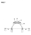
- a rotatable disk e which is called a tread stitcher is pushed against the tread ring A, the raw tire base body B is rotated and in this state, the disk e is gradually moved outward in the axial direction of the tire and inward in the radial direction, thereby pasting the entire tread ring A.
- the carcass cord is deviated from the radial direction by twist caused by rotation torque, an angle in the lateral direction is different in the belt cord, and the uniformity of a finished tire is adversely influenced. Since the shoulder side portion of the tread ring A is gradually pushed down, it takes time for pasting the tread ring A, and the productivity of the raw tire is deteriorated.
- patent document 1 Japanese Patent Application Laid-open No. S60-132745
- patent document 2 Japanese Patent Application Laid-open No. 2003-71947
- patent document 3 Japanese Patent Application Laid-open No. 2003-71948
- a wide tread ring integrally provided with a sidewall rubber is used to prevent a tread edge from becoming cracked.
- the step for moving the pasting apparatus to a predetermined position to crimp after the tread ring is transferred to the raw tire base body requires the same installation space and the cycle time of step as those of the conventional technique like the conventional disk.
- claim 1 provides a raw tire forming apparatus in which a position of a tread ring including a belt ply and a tread rubber is aligned with an outer periphery of a raw tire base body on a former in which tire members including a carcass ply are combined and the tread ring is transferred into the apparatus, the raw tire base body is expanded from its cylindrical shape to its toroidal shape, the tread ring is pushed against the toroidal raw tire base body, and the raw tire forming apparatus includes pasting means for pasting an inner peripheral surface of the tread ring to the raw tire base body, wherein the pasting means includes a ring-like base body which moves concentrically and relatively with the former in an axial direction of the tire, the ring-like base body includes a grasping tool having a plurality of segments capable of advancing and retracting in a radial direction, the segments capable of abutting against an outer peripheral surface of the tread ring to grasp the tread ring by advancing inward of an inner surface of the
- Claim 5 provides a raw tire producing method for pasting an inner peripheral surface of a tread ring including a belt ply and a tread rubber to an outer peripheral surface of a raw tire base body in which a tire member including a carcass ply is combined and which expands from its cylindrical shape into its toroidal shape on a former, wherein the method comprises a grasping step for grasping the tread ring by a grasping tool provided on a ring-like base body which relatively moves concentrically with the former in the axial direction of he tire, a positioning step for positioning the grasped tread ring with respect to the raw tire base body on the former by relative movement by the ring-like base body, an expanding step for pushing and pasting the raw tire base body to and against a central portion of the grasped tread ring by expanding the raw tire base body on the former from its cylindrical shape into its toroidal shape by charging an internal pressure, and a pasting step for pushing down a shoulder side portion of the tread ring by the rubber tube body which is disposed on each
- Fig. 1 shows a raw tire forming apparatus 1 of the present invention.
- the raw tire forming apparatus 1 is disposed between a tread ring forming drum 2 which forms a tread ring A, and a former 3 which expands a raw tire base body B from its cylindrical shape into a toroidal shape.
- the raw tire forming apparatus 1 transfers the tread ring A received from the tread ring forming drum 2 onto the former 3 while aligning the tread ring A with an outer periphery of the raw tire base body B on the former 3.
- the raw tire forming apparatus 1 also pushes an inner peripheral surface of the tread ring A against the toroidal raw tire base body B and pastes the same. That is, the raw tire forming apparatus 1 of the present invention functions as a transfer which transfers the tread ring and as a stitcher for pasting the tread ring.
- the conventional special pasting apparatus can be eliminated and the installation space can effectively be utilized.
- the tread ring forming drum 2 is of a known structure having a rotatable drum whose diameter can be reduced.
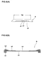
- a tread constituent member including a belt ply a1 and a tread rubber a2 is wound on the drum 2A, thereby forming the annular tread ring A (shown in Fig. 6(A)).
- the former 3 is a single former of a known structure used in a so-called single stage forming method.
- a tire member including a carcass ply b1 is wound in sequence, and a cylindrical raw tire base body B (shown in Fig. 6(B)) is formed.
- reference number b2 represents an inner linear rubber
- reference number b3 represents a bead core
- reference number b4 represents a bead apex rubber
- reference number b5 represents a sidewall rubber.
- the former 3 may be a second former used in a two stage forming method. In such a case, a raw tire base body B which is separately formed on the first former is provided on the former 3.
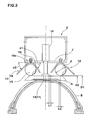
- the raw tire forming apparatus 1 includes a ring-like base body 5 which moves between the tread ring forming drum 2 and the former 3 which are concentrically disposed, and a pasting means 6 supported by this ring-like base body 5 as shown in Fig. 1.
- the pasting means 6 includes a grasping tool 11 capable of grasping the tread ring A, and a pushing-down pasting tool 12 which pushes down the tread ring shoulder side portion As and pastes the same on the toroidal raw tire base body B.
- the ring-like base body 5 is an annular body which is concentric with the former 3.
- the ring-like base body 5 has a rectangular cross section comprising an inner peripheral plate portion 7 and an outer peripheral plate portion 8 connected with each other through side plates.
- the ring-like base body 5 is provided at its lower end with a running-stage 10 which can run along rails 9 provided between the tread ring forming drum 2 and the former 3.
- the ring-like base body 5 can relatively move with respect to the former 3 in an axial direction of the tire.
- the grasping tool 11 includes a plurality of segments 13 which can move forward and backward in a radial direction. If the segments 13 move forward, i.e., inward of an inner surface of the ring-like base body 5, the segments 13 abut against the outer peripheral surface of the tread ring A and grasp the tread ring A. Although the segments 13 are supported by a rod end of a cylinder 14 fixed to the inner peripheral plate portion 7 in this embodiment, the segments 13 may be supported by any of known diameter-reducing mechanism such that the segments 13 can move while reducing the diameter.
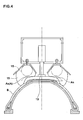
- the pushing-down pasting tool 12 includes an expandable annular rubber tube body 15 disposed on each side of the segment 13 as shown in Fig. 3.
- the pushing-down pasting tool 12 includes a guide tool 16 which guides the expansion of the rubber tube body 15.
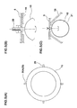
- Each rubber tube body 15 is a soft annular body having a circular cross section and a rubber thickness of 1 to 4 mm.
- the rubber tube body 15 continuously extends in a circumferential direction of the tire.
- 2 to 5 bolt-like mounting hardware 20 including air valves 20A are projecting from an outer peripheral edge of the rubber tube body 15 at distances from one another in the circumferential direction.
- the mounting hardware 20 other than the air valves 20A is fixed to the rubber tube body 15 by welding or the like.
- the mounting hardware 20 is mounted on the ring-like base body 5 with play therebetween using a double nut or the like.
- the mounting hardware 20 other than the air valve 20A may be fastened using a rubber band-like fastening cord 21 with play with respect to the ring-like base body 5.
- the fastening cord 21 is preferably easily expandable and has lower elasticity than the rubber tube body 15.
- the rubber tube body 15 is supported at a point, and the rubber tube body 15 is mounted such that it can inclined around the supporting point by play and it can easily be deviated in position.
- the guide tool 16 is formed into a V-shape having an inner guide piece 16i and an guide piece 16o each extending in the circumferential direction on each side of the rubber tube body 15.
- the inner and outer guide pieces 16i and 16o incline in directions from radially outside to inside such as to separate away from the rubber tube body 15.
- an inclination angle ⁇ 1 between the inner guide piece 16i and the axial direction of the tire is in a range of 50 to 90°
- an inclination angle ⁇ 2 between the outer guide piece 16o and the axial direction of the tire is in a range of 30 to 70° and is equal to or smaller than the inclination angle ⁇ 1
- the guide tool 16 guides such that the rubber tube body 15 expands outward as possible in the axial direction of the tire.
- the segments 13 of the raw tire forming apparatus 1 are allowed to advance radially inward and to abut against the outer peripheral surface of the tread ring A on the tread ring forming drum 2.
- the tread ring A is received from the tread ring forming drum 2 and grasped (grasping step).
- the tread ring forming drum 2 reduces its diameter to release the tread ring A.
- the raw tire forming apparatus 1 is allowed to move to a predetermined position of the former 3 along the rails 9, and the grasped tread ring A is aligned with the raw tire base body B on the former 3 (aligning step).
- the raw tire base body B on the former 3 is expanded from its cylindrical shape into the toroidal shape by charging the internal pressure.
- a central portion of the grasped tread ring A comes into contact with a central portion of the toroidal raw tire base body B under pressure and is pasted (expansion step).
- a bladder, a rubber tube and the like are made of rubber. Therefore, when it expands from its weak (thin) film portion and it naturally expands eccentrically. This eccentrically or unevenly expanded portion first pushes the tread ring or strongly pushes the tread ring. At that time, if a reinforcing layer or the like is inserted into the rubber tube and fixed without play, since a side of the rubber tube is deformed easily and a force can not be released, and the tread ring is pushed unevenly, the tread edge portion meanders and the uniformity is adversely affected.
- the rubber tube body 15 is mounted with play so that the rubber tube body 15 can easily be deviated in position.
- the rubber tube body 15 itself moves (changes its attitude) and the uneven force can be released. That is, even when stress variation in the circumferential direction or radial direction is generated in the rubber tube body 15 in some cases, the rubber tube body 15 itself moves to release the force as it is expanded, the reaction force allows it to be centered automatically with respect to the tread ring A, and the auto-correcting function can be exhibited.
- the pushing-down pasting tool 12 can precisely paste the tread ring A and the raw tire base body B with high quality. Further, the rubber tube body 15 does not require high part precision and assembling precision, and there is a merit that a shape and a structure having a simple circular cross section can be employed as the rubber tube body 15.
- the pushing-down pasting tool 12 expands the rubber tube body 15 while pushing the central portion of the tread ring A by the segments 13. Therefore, air below the tread ring A can be released toward the tread edge, and it is possible to reliably discharge the remaining air from the entire region including the central portion. Since the pasting operation can be carried out simultaneously with the transfer of the tread ring A into the raw tire base body B, the operation time can be largely reduced, and also the step cycle time can be reduced largely.
- a distance L1 in the axial direction of the tire between the segment 13 and a tip end of the inner guide piece 16i is preferably greater than 0 mm and equal to or smaller than 10 mm. If the distance L1 is 0 mm or less, when the segment 13 advances or retreats, it collides against the inner guide piece 16i. If the distance L1 exceeds 10 mm, there is an adverse possibility that air remains in this distance L1.
- the cross section diameter d of the rubber tube body 15 is preferably in a range of 25 to 100% of the tread width TW of the tread ring A (shown in Fig. 6(A)), and a distance L2 in the axial direction of the tire between the cross section center and an outer end of the widest belt ply a1 is preferably in a range of -5 to +10 mm (outer side from the outer end in the axial direction of the tire is +).
- the cross section diameter d is smaller than -25% and if the distance L2 is smaller than -5 mm, a rubber tube body 15 having a large expansion coefficient is required for pasting it up to the tread edge, the endurance strength of the rubber tube body 15 is lowered, and it takes time to charge the pressure. If the cross section diameter d exceeds 100%, the apparatus is increased in size, the installation space can not be utilized effectively, and it takes time to charge the pressure. If the distance L2 exceeds +10 mm, air is prone to remain in the tread ring shoulder side portion As. When the cross section diameter d is not a perfect circle, a diameter of the smallest perfect circle in a perfect circle capable of surrounding the cross section of the rubber tube body 15 (except air valve) is defined as the cross section diameter d.
- the inner diameter D1 of the rubber tube body 15 is preferably in a range of 100 to 110% of the outer diameter D2 of the tread ring A. If the inner diameter D1 exceeds 110% of the outer diameter D2, a rubber tube body 15 having a large expansion coefficient is required, the endurance strength of the rubber tube body 15 is lowered, and it takes time to charge the pressure.
- a charging internal pressure P1 of the rubber tube body 15 is preferably 20 to 95% of a charging internal pressure P2 of the raw tire base body B, and more preferably 30 to 80%. If the charging internal pressure P1 is smaller than 20% of the charging internal pressure P2, the pushing-down force of the tread ring shoulder side portion As is insufficient, or the pushing-down force against the raw tire base body B is insufficient, and there is an adverse possibility that the pasting operation can not be carried out reliably. If the charging internal pressure P1 exceeds 95% of the charging internal pressure P2, the raw tire base body B is deformed or the like when the pasting operation is carried out.
- the charging internal pressure P2 of the raw tire base body B can be reduced to about 30 to 80% (e.g. , 42 to 112 kPa) of the conventional stitching system (shown in Fig. 7) using a disk e.
- the charging internal pressure P2 can be suppressed.
- the charging internal pressure P2 of the raw tire base body B is usually set to a value as high as about 140 kPa, and the pushing force of the disk 3 is set to a value as high as about 140 kPa. This is because that if the charging internal pressure P2 is lower than P3, the raw tire base body B is pushed by the disk e and is deformed inward. If the pushing force P3 is 140 kPa or lower, a crimping force becomes excessively weak, the tread ring jumps and returns and the pasting operation can not be carried out. To prevent this, it is necessary to extremely reduce the rotation speed of the raw tire base body B, and the operation efficiency is largely lowered. Thus, the charging internal pressure is set to the high pressure.
- the raw tire base body B is not rotated and pushed on the circumference at a dash and thus, it is possible to push strongly within sufficient crimping time. Therefore, the charging internal pressure P1 of the rubber tube body 15 can be set to a low value while reliably carrying out the pasting operation, and the charging internal pressure P2 of the raw tire base body B can also be reduced.
- RFV radial force variation
- LFV lateral force variation
- Table 1 Conventional Example Present Example Charging internal pressure P2 140 80 (Kpa) of raw tire base body Charging internal pressure P1 - 50 (Kpa) of rubber tube body Pressing force P3 (Kpa) of disk 140 - Pasting operation time (second) 10 5 Uniformity ⁇ RFV 100 87 ⁇ LFV 100 44 Air remaining state 0 0
- Table 2 Rubber tube body ⁇ Rubber thickness (mm) 1.5 ⁇ Cross section diameter d (mm) 62 (radio d/TW) 85% ⁇ Inner diameter D1 (mm) 505 (radio D1/D2) 103% ⁇ Distance L2 (mm) 5 Guide tool ⁇ Inclination angle ⁇ 1 (°) 55 ⁇ Inclination angle ⁇ 2 (°) 45 ⁇ Distance L1 (mm) 5 * Tread width TW is 146 mm.
- Outer diameter D2 of tread ring is 488 m.
- the present invention since the present invention has both the transfer function of the tread ring and the stitcher function, the installation space can effectively be utilized, and the transfer operation and the pasting operation of the tread ring can be carried out at the same time. Therefore, the step cycle time can largely be reduced. It is unnecessary to pay much attention to misalignment, eccentricity and uneven expansion of the rubber tube, the pasting operation between the tread ring and the raw tire base body can be carried out precisely with high quality without requiring high precision of parts of the rubber tube body itself and high assembling precision. It is possible to prevent air from remaining in the entire region under the tread ring.
Landscapes
- Engineering & Computer Science (AREA)
- Mechanical Engineering (AREA)
- Tyre Moulding (AREA)
Applications Claiming Priority (2)
| Application Number | Priority Date | Filing Date | Title |
|---|---|---|---|
| JP2003179992 | 2003-06-24 | ||
| JP2003179992A JP4065220B2 (ja) | 2003-06-24 | 2003-06-24 | 生タイヤ形成装置、及び生タイヤ形成方法 |
Publications (3)
| Publication Number | Publication Date |
|---|---|
| EP1491324A2 true EP1491324A2 (de) | 2004-12-29 |
| EP1491324A3 EP1491324A3 (de) | 2005-10-19 |
| EP1491324B1 EP1491324B1 (de) | 2007-05-09 |
Family
ID=33411064
Family Applications (1)
| Application Number | Title | Priority Date | Filing Date |
|---|---|---|---|
| EP04014132A Expired - Lifetime EP1491324B1 (de) | 2003-06-24 | 2004-06-16 | Verfahren und Vorrichtung zum Aufbauen von Rohreifen |
Country Status (5)
| Country | Link |
|---|---|
| US (1) | US7208061B2 (de) |
| EP (1) | EP1491324B1 (de) |
| JP (1) | JP4065220B2 (de) |
| CN (1) | CN100562426C (de) |
| DE (1) | DE602004006339T2 (de) |
Cited By (3)
| Publication number | Priority date | Publication date | Assignee | Title |
|---|---|---|---|---|
| WO2009128046A1 (en) * | 2008-04-18 | 2009-10-22 | Pirelli Tyre S.P.A. | Process and apparatus for assembling tyres |
| EP2581208A4 (de) * | 2010-06-10 | 2013-12-04 | Bridgestone Corp | Reifenherstellungsvorrichtung und reifenherstellungsverfahren |
| JP2016117219A (ja) * | 2014-12-22 | 2016-06-30 | 住友ゴム工業株式会社 | タイヤ成形フォーマーのセンタリング確認用治具 |
Families Citing this family (15)
| Publication number | Priority date | Publication date | Assignee | Title |
|---|---|---|---|---|
| DE102004058522A1 (de) * | 2004-12-04 | 2006-06-14 | Continental Aktiengesellschaft | Verfahren und Vorrichtung zum Aufbauen eines Radialreifens |
| DE102005054507A1 (de) * | 2005-11-16 | 2007-05-24 | Continental Aktiengesellschaft | Verfahren zum Herstellen eines Gürtelpaketes für einen Fahrzeugluftreifen |
| KR101427355B1 (ko) * | 2007-09-27 | 2014-08-07 | 피렐리 타이어 소시에떼 퍼 아찌오니 | 차륜용 타이어 제조방법 및 장치 |
| JP2010208198A (ja) * | 2009-03-11 | 2010-09-24 | Bridgestone Corp | タイヤの製造方法および製造装置 |
| JP5306936B2 (ja) * | 2009-08-06 | 2013-10-02 | 株式会社ブリヂストン | タイヤ構成部材の保持搬送圧着装置および生タイヤの製造方法 |
| JP5044629B2 (ja) * | 2009-11-10 | 2012-10-10 | 住友ゴム工業株式会社 | 生タイヤ成形装置、及び空気入りタイヤの製造方法 |
| NL2004734C2 (nl) * | 2010-05-18 | 2011-11-21 | Vmi Holland Bv | Werkwijze en samenstel voor het vervaardigen van een groene band. |
| JP5732819B2 (ja) * | 2010-11-09 | 2015-06-10 | 横浜ゴム株式会社 | 未加硫ゴム部材および未加硫タイヤ圧着装置 |
| JP5695413B2 (ja) * | 2010-12-22 | 2015-04-08 | 住友ゴム工業株式会社 | 生タイヤ形成方法 |
| WO2012150948A1 (en) | 2011-04-30 | 2012-11-08 | Michelin Recherche Et Technique S.A. | Methods and apparatus for joining treads |
| JP5778980B2 (ja) * | 2011-05-13 | 2015-09-16 | 住友ゴム工業株式会社 | トレッドトランスファーを用いたトレッドトランスファーとシェーピングフォーマとの芯ズレ評価方法 |
| BR112013033157A2 (pt) | 2011-06-30 | 2017-01-31 | Michelin & Cie | métodos e aparelhos para a instalação de um anel de banda de rodagem e uma carcaça de pneu |
| CN103302882B (zh) * | 2013-07-01 | 2015-09-23 | 三角轮胎股份有限公司 | 轮胎成型工序胎面压辊装置 |
| JP6484107B2 (ja) * | 2015-05-19 | 2019-03-13 | 住友ゴム工業株式会社 | 生タイヤの形成方法 |
| US20170144400A1 (en) * | 2015-11-24 | 2017-05-25 | The Goodyear Tire & Rubber Company | Method for manufacturing a single belt/overlay component for a pneumatic tire |
Family Cites Families (10)
| Publication number | Priority date | Publication date | Assignee | Title |
|---|---|---|---|---|
| GB1147134A (en) * | 1967-03-07 | 1969-04-02 | Hill Bentham Engineering Compa | Improvements in or relating to tyre building machines |
| US3947312A (en) * | 1973-09-17 | 1976-03-30 | The General Tire And Rubber Company | Apparatus for making pneumatic tires torically with an annular guide assembly |
| JPS5149283A (en) * | 1974-10-25 | 1976-04-28 | Bridgestone Tire Co Ltd | Namataiyaseikeihoho oyobi sonosochi |
| IN148014B (de) * | 1977-02-07 | 1980-09-20 | Kentredder Ltd | |
| DE3130918A1 (de) * | 1981-08-05 | 1983-02-17 | Bayer Ag, 5090 Leverkusen | Verfahren und vorrichtung zur herstellung von radialguertelreifen |
| JPS60132745A (ja) * | 1983-12-21 | 1985-07-15 | Yokohama Rubber Co Ltd:The | タイヤの成形方法 |
| US5322587A (en) * | 1990-11-13 | 1994-06-21 | Sumitomo Rubber Industries, Ltd. | Green tire forming apparatus with transfer mechanism |
| FR2706806A1 (de) * | 1993-06-25 | 1994-12-30 | Michelin & Cie | |
| JP2003071947A (ja) | 2001-09-04 | 2003-03-12 | Yokohama Rubber Co Ltd:The | タイヤ成形装置における部材圧着装置 |
| JP2003071948A (ja) | 2001-09-04 | 2003-03-12 | Yokohama Rubber Co Ltd:The | タイヤ成形装置における部材圧着装置 |
-
2003
- 2003-06-24 JP JP2003179992A patent/JP4065220B2/ja not_active Expired - Fee Related
-
2004
- 2004-06-16 EP EP04014132A patent/EP1491324B1/de not_active Expired - Lifetime
- 2004-06-16 DE DE602004006339T patent/DE602004006339T2/de not_active Expired - Lifetime
- 2004-06-17 CN CNB2004100628017A patent/CN100562426C/zh not_active Expired - Fee Related
- 2004-06-23 US US10/873,208 patent/US7208061B2/en not_active Expired - Fee Related
Cited By (12)
| Publication number | Priority date | Publication date | Assignee | Title |
|---|---|---|---|---|
| WO2009128046A1 (en) * | 2008-04-18 | 2009-10-22 | Pirelli Tyre S.P.A. | Process and apparatus for assembling tyres |
| WO2010064077A1 (en) * | 2008-04-18 | 2010-06-10 | Pirelli Tyre S.P.A. | Process and apparatus for assembling tyres |
| CN102046360A (zh) * | 2008-04-18 | 2011-05-04 | 倍耐力轮胎股份公司 | 用于组装轮胎的方法和设备 |
| CN102046360B (zh) * | 2008-04-18 | 2013-10-16 | 倍耐力轮胎股份公司 | 用于组装轮胎的方法和设备 |
| KR101429671B1 (ko) * | 2008-04-18 | 2014-08-13 | 피렐리 타이어 소시에떼 퍼 아찌오니 | 타이어 조립방법 및 기기 |
| US8986480B2 (en) | 2008-04-18 | 2015-03-24 | Pirelli Tyre S.P.A. | Process and apparatus for assembling tyres |
| US9061476B2 (en) | 2008-04-18 | 2015-06-23 | Pirelli Tyre S.P.A. | Process and apparatus for assembling tyres |
| US10065382B2 (en) | 2008-04-18 | 2018-09-04 | Pirelli Tyre S.P.A. | Process and apparatus for assembling tyres |
| US10377101B2 (en) | 2008-04-18 | 2019-08-13 | Pirelli Tyre S.P.A. | Process and apparatus for assembling types |
| EP2581208A4 (de) * | 2010-06-10 | 2013-12-04 | Bridgestone Corp | Reifenherstellungsvorrichtung und reifenherstellungsverfahren |
| US9427925B2 (en) | 2010-06-10 | 2016-08-30 | Kabushiki Kaisha Bridgestone | Tire manufacturing apparatus and tire manufacturing method |
| JP2016117219A (ja) * | 2014-12-22 | 2016-06-30 | 住友ゴム工業株式会社 | タイヤ成形フォーマーのセンタリング確認用治具 |
Also Published As
| Publication number | Publication date |
|---|---|
| EP1491324B1 (de) | 2007-05-09 |
| JP4065220B2 (ja) | 2008-03-19 |
| EP1491324A3 (de) | 2005-10-19 |
| CN100562426C (zh) | 2009-11-25 |
| DE602004006339T2 (de) | 2008-01-10 |
| US20040261934A1 (en) | 2004-12-30 |
| US7208061B2 (en) | 2007-04-24 |
| CN1572479A (zh) | 2005-02-02 |
| DE602004006339D1 (de) | 2007-06-21 |
| JP2005014310A (ja) | 2005-01-20 |
Similar Documents
| Publication | Publication Date | Title |
|---|---|---|
| EP1491324B1 (de) | Verfahren und Vorrichtung zum Aufbauen von Rohreifen | |
| EP2698243B1 (de) | Manschettenlose Reifenbautrommel | |
| EP2868463B1 (de) | Reifenbautrommel | |
| EP2698244B1 (de) | Manschettenlose Reifenbautrommel mit auswechselbaren Breitenelementen | |
| US5268057A (en) | Tire building apparatus | |
| US7241353B2 (en) | Method of manufacturing tire | |
| US11001022B2 (en) | Method for manufacturing motorcycle tire | |
| CN108698347B (zh) | 用于构建轮胎的工艺和成套装备 | |
| US20050211366A1 (en) | Tire manufacturing method, and green tire manufacturing equipment | |
| US5248357A (en) | Process for assembling a green tire | |
| US20100269976A1 (en) | Process and plant for building tyres for vehicle wheels | |
| US7520949B2 (en) | Tire manufacturing method and tire | |
| JP4234922B2 (ja) | 自動二輪車用の空気入りタイヤの製造方法 | |
| EP0302935B1 (de) | Radialreifen für flugzeug und dessen herstellung | |
| US7060145B2 (en) | Method of making pneumatic tire | |
| KR100965999B1 (ko) | 그린타이어 제조장치 | |
| EP0432993A2 (de) | Reifenaufbautrommel | |
| JP2008221719A (ja) | 空気入りタイヤの製造方法及び生タイヤ成形装置 | |
| EP1688241B1 (de) | Radialluftreifenherstellungsverfahren und dafür verwendete gürtellaufflächenanordnungs-übertragungsvorrichtung | |
| JP4261937B2 (ja) | 空気入りタイヤの製造方法及びその装置 | |
| US20230182425A1 (en) | Tire manufacturing apparatus | |
| JP2021066074A (ja) | 空気入りタイヤの製造方法 | |
| JP2009160850A (ja) | タイヤ用成型装置 | |
| US20220258442A1 (en) | Method and device for producing green tyres | |
| JP2025074524A (ja) | 生タイヤ成形装置 |
Legal Events
| Date | Code | Title | Description |
|---|---|---|---|
| PUAI | Public reference made under article 153(3) epc to a published international application that has entered the european phase |
Free format text: ORIGINAL CODE: 0009012 |
|
| AK | Designated contracting states |
Kind code of ref document: A2 Designated state(s): AT BE BG CH CY CZ DE DK EE ES FI FR GB GR HU IE IT LI LU MC NL PL PT RO SE SI SK TR |
|
| AX | Request for extension of the european patent |
Extension state: AL HR LT LV MK |
|
| PUAL | Search report despatched |
Free format text: ORIGINAL CODE: 0009013 |
|
| AK | Designated contracting states |
Kind code of ref document: A3 Designated state(s): AT BE BG CH CY CZ DE DK EE ES FI FR GB GR HU IE IT LI LU MC NL PL PT RO SE SI SK TR |
|
| AX | Request for extension of the european patent |
Extension state: AL HR LT LV MK |
|
| 17P | Request for examination filed |
Effective date: 20051123 |
|
| AKX | Designation fees paid |
Designated state(s): DE FR GB |
|
| GRAP | Despatch of communication of intention to grant a patent |
Free format text: ORIGINAL CODE: EPIDOSNIGR1 |
|
| RIC1 | Information provided on ipc code assigned before grant |
Ipc: B29D 30/58 20060101ALI20061114BHEP Ipc: B29D 30/30 20060101ALI20061114BHEP Ipc: B29D 30/26 20060101AFI20061114BHEP |
|
| GRAS | Grant fee paid |
Free format text: ORIGINAL CODE: EPIDOSNIGR3 |
|
| GRAA | (expected) grant |
Free format text: ORIGINAL CODE: 0009210 |
|
| AK | Designated contracting states |
Kind code of ref document: B1 Designated state(s): DE FR GB |
|
| REG | Reference to a national code |
Ref country code: GB Ref legal event code: FG4D |
|
| REF | Corresponds to: |
Ref document number: 602004006339 Country of ref document: DE Date of ref document: 20070621 Kind code of ref document: P |
|
| ET | Fr: translation filed | ||
| PLBE | No opposition filed within time limit |
Free format text: ORIGINAL CODE: 0009261 |
|
| STAA | Information on the status of an ep patent application or granted ep patent |
Free format text: STATUS: NO OPPOSITION FILED WITHIN TIME LIMIT |
|
| 26N | No opposition filed |
Effective date: 20080212 |
|
| PGFP | Annual fee paid to national office [announced via postgrant information from national office to epo] |
Ref country code: FR Payment date: 20100709 Year of fee payment: 7 |
|
| PGFP | Annual fee paid to national office [announced via postgrant information from national office to epo] |
Ref country code: DE Payment date: 20100610 Year of fee payment: 7 Ref country code: GB Payment date: 20100616 Year of fee payment: 7 |
|
| GBPC | Gb: european patent ceased through non-payment of renewal fee |
Effective date: 20110616 |
|
| REG | Reference to a national code |
Ref country code: FR Ref legal event code: ST Effective date: 20120229 |
|
| REG | Reference to a national code |
Ref country code: DE Ref legal event code: R119 Ref document number: 602004006339 Country of ref document: DE Effective date: 20120103 |
|
| PG25 | Lapsed in a contracting state [announced via postgrant information from national office to epo] |
Ref country code: DE Free format text: LAPSE BECAUSE OF NON-PAYMENT OF DUE FEES Effective date: 20120103 Ref country code: FR Free format text: LAPSE BECAUSE OF NON-PAYMENT OF DUE FEES Effective date: 20110630 |
|
| PG25 | Lapsed in a contracting state [announced via postgrant information from national office to epo] |
Ref country code: GB Free format text: LAPSE BECAUSE OF NON-PAYMENT OF DUE FEES Effective date: 20110616 |