EP1491355A1 - Materiau de formation d'image multicolore - Google Patents
Materiau de formation d'image multicolore Download PDFInfo
- Publication number
- EP1491355A1 EP1491355A1 EP20030715666 EP03715666A EP1491355A1 EP 1491355 A1 EP1491355 A1 EP 1491355A1 EP 20030715666 EP20030715666 EP 20030715666 EP 03715666 A EP03715666 A EP 03715666A EP 1491355 A1 EP1491355 A1 EP 1491355A1
- Authority
- EP
- European Patent Office
- Prior art keywords
- layer
- image forming
- light
- image
- image receiving
- Prior art date
- Legal status (The legal status is an assumption and is not a legal conclusion. Google has not performed a legal analysis and makes no representation as to the accuracy of the status listed.)
- Withdrawn
Links
Images

Classifications
-
- B—PERFORMING OPERATIONS; TRANSPORTING
- B41—PRINTING; LINING MACHINES; TYPEWRITERS; STAMPS
- B41M—PRINTING, DUPLICATING, MARKING, OR COPYING PROCESSES; COLOUR PRINTING
- B41M5/00—Duplicating or marking methods; Sheet materials for use therein
- B41M5/26—Thermography ; Marking by high energetic means, e.g. laser otherwise than by burning, and characterised by the material used
- B41M5/40—Thermography ; Marking by high energetic means, e.g. laser otherwise than by burning, and characterised by the material used characterised by the base backcoat, intermediate, or covering layers, e.g. for thermal transfer dye-donor or dye-receiver sheets; Heat, radiation filtering or absorbing means or layers; combined with other image registration layers or compositions; Special originals for reproduction by thermography
- B41M5/42—Intermediate, backcoat, or covering layers
-
- B—PERFORMING OPERATIONS; TRANSPORTING
- B41—PRINTING; LINING MACHINES; TYPEWRITERS; STAMPS
- B41M—PRINTING, DUPLICATING, MARKING, OR COPYING PROCESSES; COLOUR PRINTING
- B41M5/00—Duplicating or marking methods; Sheet materials for use therein
- B41M5/26—Thermography ; Marking by high energetic means, e.g. laser otherwise than by burning, and characterised by the material used
- B41M5/40—Thermography ; Marking by high energetic means, e.g. laser otherwise than by burning, and characterised by the material used characterised by the base backcoat, intermediate, or covering layers, e.g. for thermal transfer dye-donor or dye-receiver sheets; Heat, radiation filtering or absorbing means or layers; combined with other image registration layers or compositions; Special originals for reproduction by thermography
-
- B—PERFORMING OPERATIONS; TRANSPORTING
- B41—PRINTING; LINING MACHINES; TYPEWRITERS; STAMPS
- B41J—TYPEWRITERS; SELECTIVE PRINTING MECHANISMS, i.e. MECHANISMS PRINTING OTHERWISE THAN FROM A FORME; CORRECTION OF TYPOGRAPHICAL ERRORS
- B41J2/00—Typewriters or selective printing mechanisms characterised by the printing or marking process for which they are designed
- B41J2/315—Typewriters or selective printing mechanisms characterised by the printing or marking process for which they are designed characterised by selective application of heat to a heat sensitive printing or impression-transfer material
- B41J2/32—Typewriters or selective printing mechanisms characterised by the printing or marking process for which they are designed characterised by selective application of heat to a heat sensitive printing or impression-transfer material using thermal heads
-
- B—PERFORMING OPERATIONS; TRANSPORTING
- B41—PRINTING; LINING MACHINES; TYPEWRITERS; STAMPS
- B41J—TYPEWRITERS; SELECTIVE PRINTING MECHANISMS, i.e. MECHANISMS PRINTING OTHERWISE THAN FROM A FORME; CORRECTION OF TYPOGRAPHICAL ERRORS
- B41J2/00—Typewriters or selective printing mechanisms characterised by the printing or marking process for which they are designed
- B41J2/315—Typewriters or selective printing mechanisms characterised by the printing or marking process for which they are designed characterised by selective application of heat to a heat sensitive printing or impression-transfer material
- B41J2/32—Typewriters or selective printing mechanisms characterised by the printing or marking process for which they are designed characterised by selective application of heat to a heat sensitive printing or impression-transfer material using thermal heads
- B41J2/325—Typewriters or selective printing mechanisms characterised by the printing or marking process for which they are designed characterised by selective application of heat to a heat sensitive printing or impression-transfer material using thermal heads by selective transfer of ink from ink carrier, e.g. from ink ribbon or sheet
-
- B—PERFORMING OPERATIONS; TRANSPORTING
- B41—PRINTING; LINING MACHINES; TYPEWRITERS; STAMPS
- B41M—PRINTING, DUPLICATING, MARKING, OR COPYING PROCESSES; COLOUR PRINTING
- B41M5/00—Duplicating or marking methods; Sheet materials for use therein
- B41M5/26—Thermography ; Marking by high energetic means, e.g. laser otherwise than by burning, and characterised by the material used
- B41M5/34—Multicolour thermography
- B41M5/345—Multicolour thermography by thermal transfer of dyes or pigments
-
- B—PERFORMING OPERATIONS; TRANSPORTING
- B41—PRINTING; LINING MACHINES; TYPEWRITERS; STAMPS
- B41M—PRINTING, DUPLICATING, MARKING, OR COPYING PROCESSES; COLOUR PRINTING
- B41M5/00—Duplicating or marking methods; Sheet materials for use therein
- B41M5/26—Thermography ; Marking by high energetic means, e.g. laser otherwise than by burning, and characterised by the material used
- B41M5/382—Contact thermal transfer or sublimation processes
- B41M5/38207—Contact thermal transfer or sublimation processes characterised by aspects not provided for in groups B41M5/385 - B41M5/395
- B41M5/38214—Structural details, e.g. multilayer systems
-
- B—PERFORMING OPERATIONS; TRANSPORTING
- B41—PRINTING; LINING MACHINES; TYPEWRITERS; STAMPS
- B41M—PRINTING, DUPLICATING, MARKING, OR COPYING PROCESSES; COLOUR PRINTING
- B41M5/00—Duplicating or marking methods; Sheet materials for use therein
- B41M5/26—Thermography ; Marking by high energetic means, e.g. laser otherwise than by burning, and characterised by the material used
- B41M5/40—Thermography ; Marking by high energetic means, e.g. laser otherwise than by burning, and characterised by the material used characterised by the base backcoat, intermediate, or covering layers, e.g. for thermal transfer dye-donor or dye-receiver sheets; Heat, radiation filtering or absorbing means or layers; combined with other image registration layers or compositions; Special originals for reproduction by thermography
- B41M5/46—Thermography ; Marking by high energetic means, e.g. laser otherwise than by burning, and characterised by the material used characterised by the base backcoat, intermediate, or covering layers, e.g. for thermal transfer dye-donor or dye-receiver sheets; Heat, radiation filtering or absorbing means or layers; combined with other image registration layers or compositions; Special originals for reproduction by thermography characterised by the light-to-heat converting means; characterised by the heat or radiation filtering or absorbing means or layers
-
- B—PERFORMING OPERATIONS; TRANSPORTING
- B41—PRINTING; LINING MACHINES; TYPEWRITERS; STAMPS
- B41M—PRINTING, DUPLICATING, MARKING, OR COPYING PROCESSES; COLOUR PRINTING
- B41M5/00—Duplicating or marking methods; Sheet materials for use therein
- B41M5/26—Thermography ; Marking by high energetic means, e.g. laser otherwise than by burning, and characterised by the material used
- B41M5/40—Thermography ; Marking by high energetic means, e.g. laser otherwise than by burning, and characterised by the material used characterised by the base backcoat, intermediate, or covering layers, e.g. for thermal transfer dye-donor or dye-receiver sheets; Heat, radiation filtering or absorbing means or layers; combined with other image registration layers or compositions; Special originals for reproduction by thermography
- B41M5/46—Thermography ; Marking by high energetic means, e.g. laser otherwise than by burning, and characterised by the material used characterised by the base backcoat, intermediate, or covering layers, e.g. for thermal transfer dye-donor or dye-receiver sheets; Heat, radiation filtering or absorbing means or layers; combined with other image registration layers or compositions; Special originals for reproduction by thermography characterised by the light-to-heat converting means; characterised by the heat or radiation filtering or absorbing means or layers
- B41M5/465—Infrared radiation-absorbing materials, e.g. dyes, metals, silicates, C black
-
- B—PERFORMING OPERATIONS; TRANSPORTING
- B41—PRINTING; LINING MACHINES; TYPEWRITERS; STAMPS
- B41M—PRINTING, DUPLICATING, MARKING, OR COPYING PROCESSES; COLOUR PRINTING
- B41M5/00—Duplicating or marking methods; Sheet materials for use therein
- B41M5/26—Thermography ; Marking by high energetic means, e.g. laser otherwise than by burning, and characterised by the material used
- B41M5/40—Thermography ; Marking by high energetic means, e.g. laser otherwise than by burning, and characterised by the material used characterised by the base backcoat, intermediate, or covering layers, e.g. for thermal transfer dye-donor or dye-receiver sheets; Heat, radiation filtering or absorbing means or layers; combined with other image registration layers or compositions; Special originals for reproduction by thermography
- B41M5/42—Intermediate, backcoat, or covering layers
- B41M5/423—Intermediate, backcoat, or covering layers characterised by non-macromolecular compounds, e.g. waxes
Definitions
- This invention relates to an image forming material which comprises heat transfer sheets and an image receiving sheet and is usable in a method of forming a multicolor image by irradiation with laser light.
- Such computerized systems are generally capable of reproducing dot images at 150 lines or more per inch.
- a laser beam is used as a recording head, which is capable of modulation according todigital signals and focusing into a small spot diameter.
- image forming materials that exhibithigh sensitivity to laser light and high resolution enabling reproduction of highly precise dot images.
- Image forming materials known useful in image transfer methods using laser light include a thermal melt transfer sheet, which comprises a support, a light-heat conversion layer capable of absorbing laser light to generate heat, and an image forming layer having a pigment dispersed in a heat fusible matrix (e.g., a wax or a binder) in the order described (JP-A-5-58095).
- a thermal melt transfer sheet which comprises a support, a light-heat conversion layer capable of absorbing laser light to generate heat, and an image forming layer having a pigment dispersed in a heat fusible matrix (e.g., a wax or a binder) in the order described (JP-A-5-58095).
- a thermal melt transfer sheet which comprises a support, a light-heat conversion layer capable of absorbing laser light to generate heat, and an image forming layer having a pigment dispersed in a heat fusible matrix (e.g., a wax or a binder) in the order described (JP-A
- JP-A-6-219052 teaches a heat transfer sheet comprising a support, a light-heat conversion layer containing a light-heat converting substance, a heat release layer as thin as 0.03 to 0.3 ⁇ m, and an image forming layer containing a colorant in this order.
- the heat release layer reduces its bonding strength between the image forming layer and the light-heat conversion layer upon being irradiated with laser light.
- a high precision transfer image is formed on the image receiving sheet provided on the heat transfer sheet.
- This image formation method using the above-described heat transfer sheet utilizes so-called "ablation".
- a laser-irradiated area of the heat release layer decomposes and vaporizes, resulting in reduction of the strength bonding the image forming layer and the light-heat conversion layer in that area.
- the image forming layer of that area is transferred to the image receiving sheet laminated thereon.
- Laser thermal transfer systems are capable of image formation at high resolution. Options include (1) laser sublimation, (2) laser ablation, and (3) laser melt.
- a multicolor image forming material comprising a heat transfer sheet and an image receiving sheet shows a high sensitivity of a recorded image and little change in color hue before and after exposure. It is also required to improve the stability with time of a liquid coating composition for the light-heat conversion layer.
- An object of the present invention is to provide a large size DDCP capable of providing a high quality, a high stability, a good approximation to final printed products. More specifically speaking, an object of the present invention is to provide a multicolor image forming material which is usable in a multicolor image formation method and has the following characteristics:
- the present inventors previously studied to provide DDCPs of B2/A2 or larger sizes and even of B1/A1 or larger sizes while retaining high image quality, high quality stability, and satisfactory approximation to an actual finished level.
- a laser thermal transfer recording system for DDCP which uses an image forming material characterized by capability of image transfer to the same paper as printing paper, capability of outputting true halftone dots, use of pigments as a colorant, and large sizes of B2 or larger, and an output device combined with high quality content management system (CMS) software.
- CMS high quality content management system
- Performance features of this laser thermal transfer recording system reside in (1) sharp dot formation, which offers a good approximation to final prints, (2) a satisfactory color hue approximation to final prints, (3) stable proof quality owing to performance stability against variations of the environment such as temperature and humidity and repetition, (4) a high sensitivity and a high resolution with relieved film fogging troubles of the heat transfer sheet, an excellent light resistance of the light-heat conversion layer, and a high stability with time of a liquid coating composition for forming the same, and (5) a capability of forming an image having excellent color hue and image qualities and a stable transfer density from the heat transfer sheet to the image receiving sheet even in the case of recording with the use of high-energy multibeam laser under conditions differing in temperature and humidity.
- the developed thermal transfer recording system has been realized by (1) introduction of an infrared absorbing colorant, which permits thickness reduction of a light-heat conversion layer, and a specific combination of a binder with the infrared absorbing colorant, (2) introduction of a high-Tg polymer, which enhances heat resistance of a light-heat conversion layer, (3) introduction of a heat-resistant pigment, which leads to color hue stabilization, (4) addition of a low-molecular component, such as a wax or an inorganic pigment, which controls adhesion and cohesion forces, and (5) addition of a matting agent to a light-heat conversion layer, which ensures intimate contact to an image receiving sheet without causing image quality deterioration.
- the system according to the present invention adopts a newly developed thin film thermal transfer system to accomplish high resolution and high image quality.
- the system is capable of producing a transfer image at a high resolution of 2400 dpi or more, preferably 2600 dpi or more.
- the thin film thermal transfer system is such that an image forming layer as thin as 0.01 to 0.9 ⁇ m is transferred to an image receiving sheet in the state not melted or hardly melted. In other words, the irradiated area of the image forming layer is transferred while keeping its shape as thin film so that an extremely high resolution is achieved.
- the light-heat conversion layer is thermally deformed into a dome shape on being irradiated.
- the dome-shaped light-heat conversion layer pushes the image forming layer outward, whereby the image forming layer is brought into more intimate contact with the image receiving layer and transferred thereto easily.
- Great deformation generates a great force pushing the image forming layer toward the image receiving layer and results in easy transfer.
- Small deformation produces only a small pushing force and fails to accomplish perfect transfer.
- the cross-sectional areas (a) and (b) aremeasured with a color laser 3D profile microscope VK8500 supplied by Keyence Corp.
- a deformation percentage preferred for thin film heat transfer as contemplated in the invention is 110% or higher, preferably 125% or higher, still preferably 150% or higher. While the deformation percentage could exceed 250% as long as the heat-light conversion layer has an increased elongation at break, a preferred upper limit is usually about 250%.
- the image forming layer must have a small thickness on the order of submicrons in order to attain high image quality on transfer.
- the layer should contain a pigment dispersed at a high concentration enough to give a desired image density, which conflicts with fast thermal response.
- thermal response properties also conflict with storage properties (maintenance of a high absorbance).
- the transfer interface is desirably as smooth as possible.
- surface smoothness interferes with sufficient vacuum contact.
- a relatively large amount of a matting agent having a relatively small particle size is incorporated into a layer below the image forming layer thereby to maintain a moderate uniform gap between the heat transfer sheet and the image receiving sheet.
- vacuum contact capabilities are achieved without allowing the matting agent to cause dot missing and without ruining the advantages of the thin film heat transfer technology.
- the light-heat conversion layer which converts laser light energy to heat energy reaches about 700°C
- the image forming layer containing a pigment reaches about 500°C.
- the inventors have developed a polyimide with a high heat-resistance capable of being applied by solvent coating techniques as a material of the light-heat conversion layer. They have also developed a pigment as a colorant which is more heat-resistant than pigments for printing, safe, and fit for color matching.
- a heat transfer image with sharp halftone dots can be realized and recording can be made on a print paper sheet in B2 size (515 mm x 728 mm) or larger.
- a system enabling printing on a paper sheet of 543 mm x 765 mm (B2 size) or larger is still preferred.
- One of the performance features of the system developed by the present invention is capability of forming sharp dots.
- the resolution achievable wi th this system is 2000 dpi or higher, preferably 2400 dpi or higher, and a transfer image having a resolution according to a desired number of lines per inch (lpi) can be obtained by the system.
- the individual dots have very sharp edges substantially free from blur or deficiency. Full range of dots from highlights to shadows can be formed clearly. Therefore, the system is capable of outputting high quality dots at the same level of resolution as obtained with an image setter or a CTP setter to give an approximation to dots and gradation of final printed products.
- a second performance feature of the system developed by the present invention is satisfactory cyclic reproducibility. Since the image forming layer can be transferred in sharp dots, dots are reproduced in good agreement with a laser beam. Additionally, because of very small environmental humidity/temperaturedependencyof recording characteristics, the results of repetition are stable in color hue and density in a wide range of environmental conditions.
- a third performance feature of the system developed by the present invention is satisfactory color reproducibility. Since the system employs the same pigments as used in printing inks and has satisfactory cyclic reproducibility, highly accurate color management system (CMS) can be realized.
- CMS color management system
- the heat transfer image obtained substantially matches the color hues of final prints, i.e., the hues of Japan-colors, SWOP colors or the like and shows the same change in what it looks like with a change of lighting (e.g., a fluorescent lamp and an incandescent lamp) as the final printed product.
- a change of lighting e.g., a fluorescent lamp and an incandescent lamp
- a fourth performance feature of the system developed by the present invention is satisfactory text quality. Owing to the sharp dot shape, the system reproduces fine lines of letters with sharp edges.
- Thermal transfer techniques for DDCP include: (1) laser sublimation; (2) laser ablation; and (3) laser melt.
- the systems (1) and (2) result in blurred dot edges because of sublimation or scattering of a colorant.
- the system (3) also fails to create clear dot outlines because the molten colorant flows.
- the present inventors have adopted the thin film thermal transfer system as a base and further employed the following material techniques.
- a first material feature of the system is a sharper dot edge.
- laser light is converted to heat in the light-heat conversion layer, the heat is transmitted to the adjoining image forming layer, and the image forming layer adheres to the image receiving layer to conduct recording.
- the heat generated by laser light it is required that the heat generated by laser light be transmitted right to the transfer interface without being diffused in the planar direction so that the image forming layer may be cut sharply along the borders between heated areas and non-heated areas.
- the light-heat conversion layer of the heat transfer sheet should be reduced in thickness, and the dynamic characteristics of the image forming layer should be so controlled.
- a first technique for accomplishing dot sharpening is thickness reduction of the light-heat conversion layer.
- a light-heat conversion layer is assumed to instantaneously reach about 700°C so that a thin light-heat conversion layer is liable to undergo deformation or destruction. A deformed or destroyed thin light-heat conversion layer would be transferred to an image receiving sheet together with an image receiving layer or result in an uneven transfer image.
- a light-heat conversion layer must have a light-heat converting substance in a high concentration so as to reach a prescribed temperature, which can cause additional problems such as colorant's precipitation or migration to an adjacent layer.
- the heat transfer sheet of the invention employs an infrared absorbing colorant as a light-heat converting substance which is effective at a reduced amount compared with carbon that has been often used as a light-heat converting substance.
- an infrared absorbing colorant as a light-heat converting substance which is effective at a reduced amount compared with carbon that has been often used as a light-heat converting substance.
- a binder a polyamide-imide resin which retains sufficient mechanical strength even at high temperatures and has satisfactory ability to hold an infrared absorbing colorant is selected.
- the light-heat conversion layer thickness is reduced to about 0.5 ⁇ m or smaller by selecting an infrared absorbing colorant exhibiting excellent light-heat conversion characteristics and a heat-resistant binder such as a polyamide-imide resin.
- the combined use of the infrared absorbing colorant and the polyamide-imide resin in the light-heat conversion layer produces the following effects.
- the storage stability of a liquid coating composition for light-heat conversion layer is improved thereby to prevent reduction in absorbance of the light-heat conversion layer that might occur due to storage of the liquid coating composition.
- the absorbance of the light-heat conversion layer is increased, which leads to improved sensitivity. Change in color hue between before and after irradiation is reduced to improve light resistance.
- a second technique for dot sharpening is for improving the characteristics of the image forming layer.
- the image forming layer transferred to the image receiving layer suffers from thickness unevenness in response to the slow scanning pattern of a laser beam. It follows that the transfer image becomes non-uniform with reduced apparent transfer densities. This tendency becomes conspicuous with a decrease in image forming layer thickness. On the other hand, a thick image forming layer has poor dot sharpness and reduced sensitivity.
- a low-melting substance such as a wax
- fine inorganic particles can be added in place of part of binders to increase the layer thickness to a proper degree so that the image forming layer may be sharply cut along the heated area/non-heated area interface. As a result,uniform recording can be accomplished without impairing dot sharpness and sensitivity.
- low-melting substances such as waxes tend to bleed on the surface of the image forming layer or to crystallize, which can result in impairment of image quality or deterioration of stability of the heat transfer sheet with time.
- a low-melting substance with a small difference in Sp (solubility parameter) value from the polymer of the image forming layer.
- Such a substance exhibits improved compatibility with the polymer and is prevented from releasing from the image forming layer. It is also preferred for averting crystallization that a plurality of low-melting substances having different structures are mixed into an eutectic mixture. By these manipulations an image of sharp dots free from unevenness can be obtained.
- a second material feature of the system owes to the finding that thermal transfer recording sensitivity is dependent on temperature and humidity.
- the heat transfer sheet changes its mechanical and thermal characteristics on moisture absorption, which means environmental humidity dependence of recording.
- an organic solvent system as the colorant/binder system of the light-heat conversion layer and the binder system of the image forming layer.
- polyvinyl butyral as a binder of the image receiving layer and to introduce a polymer hydrophobilization technique for reducing the water absorption of polyvinyl butyral.
- Available polymer hydrophobilization techniques include causing a hydroxyl group of a polymer to react with a hydrophobic group as taught in JP-A-8-238858 and crosslinking two or more hydroxyl groups of a polymer with a hardening agent.
- a third material feature of the system lies in improvement on color hue approximation to the final output.
- the system of the invention has introduced the knowledge about color matching management and stable dispersing technique amassed through the development of a thermal head type color proffer (e.g., First Proof supplied by Fuji Photo Film Co., Ltd.) and also settled the following problem that has arisen in the laser thermal transfer system.
- a first technique for achieving improved color hue approximation to the final output consists in use of a highly heat-resistant pigment.
- An image forming layer generally reaches about 500°C in thermal transfer recording by laser light exposure. Some of traditionally employed pigments decompose at such high temperatures. This problem is averted by using highly heat-resistant pigments in the image forming layer.
- a second technique realizing improved color hue approximation to the final output resides in prevention of the infrared absorbing colorant from diffusing. If the infrared absorbing colorant used in the light-heat conversion layer migrates to the image forming layer due to the high recording heat, it follows that the color hue of a resultant transfer image differs from what is expected. To prevent this, the light-heat conversion layer is preferably made of the infrared absorbing colorant combined with the above-described binder capable of securely holding the infrared absorbing colorant.
- a fourth material feature of the system is achievement of high sensitivity.
- shortage of light energy often occurs to cause gaps, particularly gaps corresponding to the scanning pitch in the slow laser scanning direction.
- the high concentration of a colorant (pigment) in the light-heat conversion layer and the small thicknesses of the light-heat conversion layer and the image forming layer serve to increase the efficiency of heat generation and heat conduction as previously stated.
- polyvinyl butyral which is a preferred binder for use in the image forming layer, as a binder of the image receiving layer so as to increase the adhesion between the image receiving layer and the image forming layer and to ensure the film strength of the transfer image.
- a fifth material feature of the system is improvement on vacuum holding.
- the image receiving sheet and the heat transfer sheet are preferably held on a recording drum by vacuum holding.
- the contact of the two sheets by vacuum holding is of great significance because image transfer relies on control of adhesion between the image receiving layer of the image receiving sheet and the image forming layer of the transfer sheet, and the transfer behavior is very sensitive to the clearance therebetween.
- An increased gap between the two sheets due to dust or debris results in image defects or transfer unevenness.
- a first technique for improving vacuum holding is to give surface roughness to the heat transfer sheet. Surface roughness is given to the heat transfer sheet side so that the effect of vacuum contact may be fully enjoyed when two or more color images are overprinted.
- the heat transfer sheet can be textured by post-treatments such as embossing or addition of a matting agent. Addition of a matting agent is preferred for the sake of process simplification and in view of material stability with time.
- a matting agent to be added should have a particle size larger than the thickness of a layer to which it is added. Addition of a matting agent directly to the image forming layer would result in missing of dots from the part where the matting agent particles stick but.
- the image forming layer provided thereon has an almost uniform thickness and is capable of transferring a defect-free image to the image receiving sheet.
- a sixth material feature of the system relates mainly to the second embodiment of the present invention, that is, improvement in the image forming layer of the heat transfer sheet.
- the objects of the invention can be established even though no polyamide-imide'is employed as the binder in the light-heat conversion layer.
- Heat transfer sheets having these characteristics can be constructed by an arbitrary method without particular restriction. As specific examples thereof, citation may be made of selecting a binder and a light-heat converting substance in the light-heat conversion layer of a heat transfer sheet from among those which will be described hereinafter to thereby control, using a colorless colorant and a colorless colorant decomposition product, bleaching a colorant and a colorant decomposition product, and so on.
- a first feature of the systematization is configuration of the recording apparatus.
- the recording apparatus which can be used has the same basic configuration as conventional thermal transfer recorders.
- This configuration is a so-called heat mode outer drum recording system in which a heat transfer sheet and an image receiving sheet held on a drum are irradiated with a recording head having a plurality of high power lasers.
- the following embodiments are preferred among others.
- the recording apparatus is designed to avoid contamination with dust.
- the image receiving sheet and the heat transfer sheet are supplied by a full-automatic roll supply system so as to avoid contamination with dust or debris that might enter if the recording apparatus is manually loaded with a stack of cut sheets.
- the recording apparatus is designed to bring the image receiving sheet and the heat transfer sheet into intimate contact on the recording drum.
- the image receiving sheet and the heat transfer sheet are held to the drum by suction (vacuum holding). Mechanical holding fails to bring the two sheets into such intimate contact as obtained by vacuum holding.
- a large number of suction holes are formed on the recording drum, and the inside of the drum is evacuated with a blower or a vacuum pump thereby to hold the sheets onto the drum.
- the image receiving sheet is the first to be held by suction, and the heat transfer sheet is superposed thereon. Therefore, the heat transfer sheet is made larger than the image receiving sheet so as to have extensions over every side of the image receiving sheet. Air between the heat transfer sheet and the image receiving sheet, which greatly influences the image transfer, is sucked from the extension area of the heat transfer sheet extending from the underlying image receiving sheet.
- the recording apparatus is designed to allow a plurality of output sheets to be stacked stably on an output tray.
- the recording apparatus is contemplated to provide output sheets of B2 or larger sizes being stacked on the output tray.
- the two sheets can stick to each other because of the heat stickiness of the image receiving layer. If this happens, the next sheet is not discharged in good order to cause jamming. To prevent this from happening, it is the best to prevent the output films A and B from coming into contact with each other.
- Known means for preventing the contact include (a) a level difference made on the output tray, by which the film is placed non-flat, and a gap is created between adjacent films, (b) a slot for output exit positioned higher than the output tray so that an output film discharged through the slot drops on the output tray, and (c) air ejected between adjacent films to float the film discharged later. Since the sheet size is as large as B2, application of the means (a) or (b) will make the apparatus considerably larger. Therefore, the means (c), i.e., an air ejection method is employed in this system. That is, air is ejected between films to float the sheet discharged later.
- Fig. 2 shows an example of the configuration of a recording apparatus 1 which can be used in the invention.
- an adhesive roller having a pressure-sensitive adhesive material on the surface as one of paired feed rollers 7 disposed on any site of the image receiving sheet roll and the heat transfer sheet roll.
- the adhesive roller By providing the adhesive roller, the surface of the heat transfer sheet and the image receiving sheet can be cleaned.
- Examples of the pressure-sensitive adhesive provided on the surface of the adhesive roller includes an ethylene-vinyl acetate copolymer, an ethylene-ethyl acrylate copolymer, a polyolefin resin, a polybutadiene resin, a styrene-butadiene copolymer (SBR), a styrene-ethylene-butene-styrene copolymer (SEBS), an acrylonitrile-butadiene copolymer (NBR), a polyisoprene resin (IR), a styrene-isoprene copolymer (SIS), an acrylic ester copolymer, a polyester resin, a polyurethane resin, an acrylic resin, butyl rubber, and polynorbornene.
- SBR styrene-butadiene copolymer
- SEBS styrene-ethylene-butene-styrene copolymer
- NBR
- the surface of the heat transfer sheet and the image receiving sheet can be cleaned on contact with the adhesive roller.
- the contact pressure is not particular limited.
- the pressure-sensitive adhesive used in the adhesive roller has a Vickers hardness Hv of 50 kg/mm 2 ( ⁇ 490 MPa) or less for thoroughly removing dust and thereby preventing image defects caused by dust.
- the pressure-sensitive adhesive it is also preferred for the pressure-sensitive adhesive to have an elastic modulus of 200 kg/cm 2 ( ⁇ 19.6MPa) or less at 20°C for the same purpose as described above, i.e., for thoroughly removing dust and thereby preventing image defects caused by dust.
- a second feature of the systematization is configuration of a heat transfer apparatus.
- a heat transfer apparatus is used to carry out the step of re-transferring the transfer image on the image receiving sheet to a sheet of the same paper as used in final printing (hereinafter simply referred to as a paper sheet).
- This step is entirely identical to that carried out in First Proof (a trade mark of a thermal transfer apparatus available from Fuji Photo FilmCo., Ltd.).
- a paper sheet is superposed on the image receiving sheet, and heat and pressure are applied thereto to adhere the two sheets together. Then, the image receiving film is stripped off from the paper sheet, whereby only the support and a cushioning layer of the image receiving sheet are removed to leave the image and the adhesive layer on the paper sheet. This practically means that the image is transferred from the image receiving sheet to the printing paper sheet.
- First ProofTM image re-transfer is performed by superposing a paper sheet and the image-receiving sheet on an aluminum guide plate and passing them through a pair of heat rollers.
- the aluminum guide plate serves to prevent the paper from deformation.
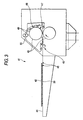
- the aluminum guide plate should be larger than a B2 size, which results in the problem that a large installation space is required. Accordingly, the system of the present invention does not use such an aluminum guide plate. Instead, the carrier path turns 180° so that the sheets are discharged toward the loading side. As a result, the installation space can be largely saved (see FIG. 3).
- the paper sheet is curled in the absence of an aluminum guide plate.
- the facing couple of the paper sheet and the image-receiving sheet curls with the image-receiving sheet inward and rolls on the output tray. It is very difficult to separate the image receiving sheet from the curled paper.
- this curling phenomenon is averted by taking advantage of bimetallic effect due to the difference in shrinkage between printing paper and the image receiving sheet and the ironing effect of the heat roller.
- an image receiving sheet is superposed on a paper sheet as in a conventional way
- the two sheets curl with the image receiving sheet inward by bimetallic effect upon heating because the image receiving sheet shows larger thermal shrinkage in the direction of insertion than printing paper.
- the direction of curling by the bimetallic effect is the same as the direction of curling by the ironing effect of the heat roller around which the two sheets are wound.
- the curling becomes serious by synergism.
- downward curling by the bimetallic effect occurs whereas upward curling is caused by ironing effect so that the curls of opposite directions are offset by each other.
- Re-transfer to printing paper is carried out according to the following sequence (hereinafter called thepaper transfer method to be use din this system).
- a thermal transfer apparatus 41 which can be used for re-transfer is shown in Fig. 3. Unlike the laser recording apparatus, the thermal transfer apparatus 41 is manually operated.
- the second feature of the systematization technique resides in the system configuration.
- the above-illustrated apparatus are connected to a plate-making system to perform the function as a color proofer.
- a color proofing system is required to output a color proof as an approximation to final prints outputted based on certain page data. Therefore, software for approximating dots and colors to the final prints is necessary.
- a specific example of connection is shown below.
- a CTP system is connected to Celebra.
- a printing plate outputted from this connection is mounted on a press to carry out actual printing.
- To Celebra is connected the above-illustrated thermal transfer recording apparatus as a color proofer, e.g., Luxel FINALPROOF 5600 from Fuji Photo Film Co., Ltd. (hereinafter simply referred to as FINALPROOF), and proof drive software PD SYSTEMTM available from Fuji Photo Film is installed between Celebra and FINALPROOF for approximating dots and colors to the final output.
- FINALPROOF proof drive software
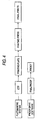
- Contone data continuous tone data converted to raster data by Celebra are converted to binary data for dots, outputted to the CTP system, and finally printed.
- the same contone data are also sent to PD SYSTEM.
- PD SYSTEM converts the received data according to a four-dimensional (black, cyan, magenta and yellow) table for each color so that the colors may agree with the final output.
- the data are converted to binary data for dots so as to agree with the dots of the final output, which are sent to FINALPROOF (Fig. 4).
- the four-dimensional table for each color as described above is experimentally prepared in advance and stored in the system.
- the experiment for the preparation of the four-dimensional table is as follows. Data of an important color are outputted via the CTP system to prepare a printed image. The same data are also outputted from FINALPROOF via PD. SYSTEM to prepare a proof image. The measured chromaticities of these images are compared, and a table is prepared so as to minimize the difference.
- the system configuration is set up so that the performance of the high-resolution image forming elements of the invention may be exhibited to the full.
- the absolute value of the difference in surface roughness Rz between the exterior and the interior sides of the image forming layer of the heat transfer sheet is 3.0 ⁇ m or smaller and that the absolute value of the difference in surface roughness Rz between the exterior and the interior sides of the image-receiving layer of the image receiving sheet is 3.0 ⁇ m or smaller.
- the surface roughness Rz is a 10 point height parameter corresponding to the Rz (maximum height) specified in JIS.
- the surface roughness Rz is obtained by computing the average height difference between the five highest peaks and the five lowest valleys with respect to the mean plane within an evaluation area.
- a stylus type 3D roughness meter (Surfcom 570A-3DF, available from Tokyo Seimitsu Co., Ltd.) is used for measurement. The measurement is performed in the longitudinal direction, the cut-off length is 0.08 mm, the evaluation area is 0.6 mm by 0.4 mm, the sampling pitch is 0.005 mm, and the speed of measurement is 0.12 mm/sec.
- the absolute difference in Rz between the exterior and the interior surfaces of the image forming layer is 1.0 ⁇ m or smaller and that the absolute difference in Rz between the exterior and the interior sides of the image receiving layer is 1.0 ⁇ m or smaller.
- the surface roughness Rz of both the exterior and the interior sides of the image forming layer of the heat transfer sheet and/or both the exterior and the interior sides of the image receiving layer of the image receiving sheet are in a range of from 2 to 30 ⁇ m.
- each heat transfer sheet it is preferred for the image forming layer of each heat transfer sheet to have a gloss of 80 to 99.
- the gloss of the image forming layer largely depends on the smoothness of the layer and relates to the thickness uniformity of the layer.
- An image forming layer with a higher gloss has higher thickness uniformity and is more suited for high precision image formation.
- higher smoothness leads to higher resistance in sheet transportation i.e., being in a trade-off.
- the surface gloss ranges 80 to 99, a balance between smoothness and transportation resistance will be achieved.
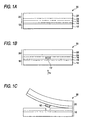
- An image forming laminate 30 composed of an image receiving sheet 20 laminated on an image forming layer 16 containing a pigment (black (K), cyan (C), magenta (M), yellow (Y), etc.) of a heat transfer sheet 10 is prepared.
- the heat transfer sheet 10 comprises a support 12, a light-heat conversion layer 14 provided on the support 12, and the image forming layer 16 provided on the light-heat conversion layer 14.
- the image receiving sheet 20 has a support 22 and an image receiving layer 24 provided thereon. The two sheets 10 and 20 are superposed with the image receiving layer 24 facing the image forming layer 16 (Fig. 1 (a)).
- the irradiated area of the light-heat conversion layer 14 of the heat transfer sheet 10 generates heat to reduce its adhesion to the image forming layer 16 (see Fig. 1(b)).
- the heat transfer sheet 10 is stripped off the image receiving sheet 20 while leaving the irradiated area 16' of the image forming layer 16 on the image receiving layer 24 of the image receiving sheet 20. That is, the image is transferred (see Fig. 1(c)).
- the laser light for imagewise irradiation preferably comprises multibeams, particularly multibeams of two-dimensional array.
- Multibeams of two-dimensional array are a plurality of laser beams arranged in a two-dimensional array such that the spots of these laser beams form a plurality of lines in the fast scan direction and a plurality of rows in the slow scan direction.
- a laser beam is preferably emitted to give a spot diameter of 5 to 50 ⁇ m, particularly 6 to 30 ⁇ m, on the light-heat conversion layer.
- the scanning speed is preferably 1 m/sec or higher, still preferably 3 m/sec or higher, still preferably 5 m/sec or higher and particularly preferably 8 m/sec or higher.
- the. light source wavelength of the laser light is from 750 to 850 nm.
- the energy supplied to the light-heat conversion layer in image recording by laser irradiation is 300mJ/m 2 or less, particularly preferably from 200 to 250 mJ/m 2 .
- the thickness of the black image forming layer in the black heat transfer sheet is preferably larger than that of the other image forming layers of the other heat transfer sheets (e.g., yellow, magenta, cyan, etc.) and preferably ranges from 0.5 to 0.7 ⁇ m.
- This layer design is effective to prevent density reduction due to non-uniform transfer of the black image forming layer.
- the black image forming layer With the thickness being 0.5 ⁇ m or greater, the black image forming layer can be uniformly transferred when recorded with high energy thereby attaining a satisfactory image density necessary as a color proof for printing. Since the tendency to transfer unevenness becomes conspicuous under high humidity conditions, the thickness as defined above is particularly effective to reduce environment-induced variations in density. On the other hand, the black image forming layer thickness of 0.7 ⁇ m or smaller is effective in maintaining the transfer sensitivity in laser recording and improving reproducibility of small dots and fine lines. These effects are more conspi cuous under lower humidity conditions. Resolution can also be improved with the above layer thickness.
- the layer thickness of the black image forming layer of the black heat transfer sheet is still preferably from 0.55 to 0.65 ⁇ m, particularly preferably 0.60 ⁇ m.
- the thickness of the other color image forming layers of the other heat transfer sheets e.g., yellow, magenta, cyan, etc.
- the thickness of the other color image forming layers of the other heat transfer sheets is from 0.2 to less than 0.5 ⁇ m.
- the 0.2 ⁇ m or greater thickness of these image forming layers is effective to prevent transfer unevenness thereby to maintain the image density in laser recording.
- the thickness of these color image forming layers being less than 0.5 ⁇ m, the transfer sensitivity and resolution are improved.
- a still preferred thickness is from 0.3 to 0.45 ⁇ m.
- the black image forming layer of the black heat transfer sheet prefferably contains carbon black.
- the carbon black to be incorporated preferably comprises at least two kinds different in tinting strength from the viewpoint of ease of controlling reflection density while maintaining a P/B (pigment/binder) ratio within a specific range.
- the tinting strength of carbon black can be represented in various terms.
- PVC blackness disclosed in JP-A-10-140033 is among them.
- PVC blackness of carbon black is determined as follows. Carbon black to be evaluated is dispersed in a polyvinyl chloride (PVC) resin by a two-roll mill and molded into a sheet. The blacknesses of Carbon Black #40 and #45, both available from Mitsubishi Chemicals Co., Ltd. being taken as 1 point and 10 points, respectively, the PVC blackness of the sample sheet is rated by visual observation on a 10 point scale. Two or more carbon blacks having different PVC blacknesses can be used in an appropriate combination according to the purpose.
- a low-density polyethylene (LDPE) resin is mixed with 40% by mass of a carbon black sample and kneaded at 115°C for 4 minutes.
- the obtained blend is diluted in a two-roll mill at 120°C to give a carbon black content of 1% by mass.
- the resulting compound is extruded through a slit width of 0.3 mm, and the extruded sheet is cut into chips.
- the chips are molded into a film having a thickness of 65 ⁇ 3 ⁇ m on a hot plate set at 240°C.
- the latter method is carried out, for example, as follows.
- Heat transfer sheets having image forming layers containing coloring matters with different colors are prepared.
- an image forming laminate with combination of an image receiving sheet and a heat transfer sheet is prepared for each of four colors (cyan, magenta, yellow and black).
- Each laminate is irradiated with laser light in accordance with the respective digital signals (e.g., through a color separation filter), and the heat transfer sheet is stripped off from the image receiving sheet to obtain a color separated image for each color on the image receiving sheet.
- the color separated images are successively re-transferred to an actual support, such as printing paper or an equivalent, to form a multicolor image.
- the resolution of the image transferred from the image forming layer of the heat transfer sheet to the image receiving layer of the image receiving sheet can be controlled to 2000 dpi or hither, preferably 2400 dpi or higher.
- a heat transfer sheet using laser irradiation is preferably usable in the thin film heat transfer system wherein laser beams are converted into heat and, using the heat energy, an image forming layer containing a pigment is transferred to an image receiving sheet to form an image.
- the technology employed in developing these image formingmaterials comprising the heat transfer sheets and the image receiving sheet is also applicable to other thermal transfer systems, such as melt transfer recording, ablation transfer recording, and sublimation transfer recording. Therefore, the system of the invention includes in its scope the image forming materials useful in these other thermal transfer recording systems.
- the heat transfer sheets each comprises a support, a light-heat conversion layer, and an image forming layer and an optional layer(s).
- the support of the heat transfer sheet can be of any material of choice. It is desirable for the support to have stiffness, dimensional stability, and heat resistance withstanding the heat of laser recording.
- Preferred support materials include synthetic resins, such as polyethylene terephthalate, polyethylene-2,6-naphthalate, polycarbonate, polymethyl methacrylate, polyethylene, polypropylene, polyvinyl chloride, polyvinylidene chloride, polystyrene, styrene-acrylonitrile copolymers, polyamide (aromatic or aliphatic), polyimide, polyamide-imide, and polysulfone.
- a biaxially stretched polyethylene terephthalate film is preferred of them from the standpoint of mechanical strength and dimensional stability against heat.
- the support of the heat transfer sheet is preferably made of transparent synthetic resins which transmit laser beams.
- the thickness of the support is preferably from 25 to 130 ⁇ m, still preferably from 50 to 120 ⁇ m.
- the support preferably has a center-line average surface roughness Ra of less than 0.1 ⁇ m on its image forming layer side (measured in accordance with JIS B0601 with, for example, a profilometer (e.g., Surfcom available from Tokyo Seiki Co., Ltd.).
- the support preferably has a Young's modulus of from 200 to 1200 kg/mm2 ( ⁇ 2 to 12 GPa) in the machine direction and of from 250 to 1600 kg/mm 2 ( ⁇ 2.5 to 16 GPa) in the transverse direction.
- the F-5 value of the support in the machine direction is preferably from 5 to 50 kg/mm 2 ( ⁇ 49 to 490 MPa), and that in the transverse direction is preferably from 3 to 30 kg/mm 2 ( ⁇ 29.4 to 294 MPa).
- the F-5 value in the machine direction is generally higher than that in the transverse direction, but this is not the case when the support is required to be stronger in the transverse direction than in the machine direction.
- the thermal shrinkage of the support when treated at 100°C for 30 minutes is preferably 3% or less, still preferably 1.5% or less, in both transverse direction and machine direction.
- the thermal shrinkage at 80°C for 30 minutes is preferably 1% or less, still preferably 0.5% or less, in both machine direction and transverse direction.
- the support preferably has a breaking strength of 5 to 100 kg/mm 2 ( ⁇ 49 to 980 MPa) in both directions and an elastic modulus at 20°C of 100 to 2,000 kg/mm 2 ( ⁇ 0.98 to 19.6 GPa).
- the support may be subjected to a surface activation treatment and/or be provided with one or more undercoating layers.
- the surface activation treatment includes glow discharge treatment and corona discharge treatment.
- the material of the undercoating layer is preferably selected from those having high adhesion to both the support and the light-heat conversion layer, low heat conductivity, and high heat resistance. Such materials include styrene, a styrene-butadiene copolymer, and gelatin.
- the total thickness of the undercoating layers is generally from 0.01 to 2 ⁇ m.
- the opposite side of the support may al so be surface-treated or provided with a functional layer, such as an antireflection layer or an antistatic layer. It is particularly advisable to provide a backcoating layer containing an antistatic agent on the back of the support.
- the backcoating layer preferably comprises a first backcoating layer contiguous to the support and a second backcoating layer provided on the first backcoating layer.
- the weight ratio of the antistatic agent B contained in the second backcoating layer to the antistatic agent A contained in the first backing layer, B/A is less than 0.3.
- a B/A ratio of 0.3 or more tends to result in reduction of sliding properties and cause powder fall-off from the backcoating layer.
- the thickness C of the first backcoating layer is preferably from 0.01 to 1 ⁇ m, still preferably from 0.01 to 0.2 ⁇ m.
- the thickness D of the second backcoating layer is preferably from 0.01 to 1 ⁇ m, still preferably from 0.01 to 0.2 ⁇ m.
- the thickness ratio C:D is preferably from 1 :2 to 5:1.
- the antistatic agents which can be used in the first and second backcoating layers include nonionic surface active agents, e.g., polyoxyethylene alkylamines and glycerol fatty acid esters; cationic surface active agents, e.g., quaternary ammonium salts; anionic surface active agents, e.g., alkylphosphates; amphoteric surface active agents; and electrically conductive resins.
- nonionic surface active agents e.g., polyoxyethylene alkylamines and glycerol fatty acid esters
- cationic surface active agents e.g., quaternary ammonium salts
- anionic surface active agents e.g., alkylphosphates
- amphoteric surface active agents e.g., alkylphosphates
- electrically conductive resins e.g., electrically conductive resins.
- Fine electrically conductive particles can also be used as an antistatic agent.
- examples of such fine electrically conductive particles include oxides, e.g., ZnO, TiO 2 , SnO 3 , Al 2 O 3 , In 2 O 3 , MgO, BaO, CoO, CuO, Cu 2 O, CaO, SrO, BaO 2 , PbO, PbO 2 , MnO 2 , MoO 3 , SiO 2 , ZrO 2 , Ag 2 O, Y 2 O 3 , Bi 2 O 3 , Ti 2 O 3 , Sb 2 O 3 , Sb 2 O 5 , K 2 Ti 6 O 13 , NaCaP 2 O 18 , and MgB 2 O 5 ; sulfides, e.g., CuS and ZnS; carbides, e.g., SiC, TiC, ZrC, VC, NbC, MoC, and WC; nitrides, e.g., Si 3
- These electrically conductive substances may be used either alone or in a combination of two or more thereof.
- SnO 2 , ZnO, Al 2 O 3 , TiO 2 , In 2 O 3 , MgO, BaO, and MoO 3 are preferable, SnO 2 , ZnO, In 2 O 3 , and TiO 2 are still preferable, and SnO 2 is particularly preferred.
- the antistatic agents used in the backcoating layer are preferably substantially transparent so as to transmit laser beams.
- the particle size is preferably as small as possible to minimize light scattering, but the particle size should be determined based on the ratio of the refractive index of the particles to that of the binder as a parameter, which can be obtained according to Mie theory.
- the average particle size is generally from 0.001 to 0.5 ⁇ m, preferably from 0.003 to 0.2 ⁇ m.
- the term "average particle size" as used herein is intended to cover not only primary particles but agglomerates.
- the first and second backcoating layers may further contain a binder and various other additives, such as surface active agents, slip agents, andmatting agents as well as binders.
- the amount of the antistatic agent in the first backcoating layer is preferably from 10 to 1,000 parts by mass, still preferably from 200 to 800 parts by mass, per 100 parts by mass of the binder.
- the amount of the antistatic agent in the second backcoating layer is preferably from 0 to 300 parts by mass, still preferably from 0 to 100 parts by mass, per 100 parts by mass of the binder.
- the binders which can be used in the first and second backcoating layers include homopolymers and copolymers of acrylic monomers, e.g., acrylicacid, methacrylicacid, acrylic esters and methacrylic esters; cellulosic polymers, e.g., nitrocellulose, methyl cellulose, ethyl cellulose, and cellulose acetate; polymers of vinyl compounds, e.g., polyethylene, polypropylene, polystyrene, vinyl chloride copolymers, vinyl chloride-vinyl acetate copolymers, polyvinyl pyrrolidone, polyvinyl butyral, and polyvinyl alcohol; condensed polymers, e.g., polyester, polyurethane, and polyamide; elastic thermoplastic polymers, e.g., butadiene-styrene copolymers; polymers obtained by polymerization or crosslinking of photopolymerizable or heat polymerizable compounds, e.g.
- the light-heat conversion layer comprises a light-heat converting substance and a binder. If necessary, it can contain a matting agent. It may further contain other additives, if desired.
- a polyamide-imide is used as the binder.
- the polyamide-imide is not restricted in type so long as it can serve as a binder, it is preferable to employ a polyamide-imide having strength enough to form a layer on the support and a high heat conductivity, still preferably a polyamide-imide having such heat resistance so as not to decompose by the heat generated by the light-heat converting substance, since the surface smoothness of the light-heat conversion layer can be maintained after irradiation with high energy light.
- the polyamide-imide as the binder preferably has a heat decomposition temperature of 400°C or higher, particularly 500°C or higher, as measured by TGA (thermogravimetric analysis) at a temperature rise rate of 10°C/min.
- the binder of the light-heat conversion layer prefferably has higher heat resistance (e.g., heat deformation temperature and heat decomposition temperature) than the materials used in other layers provided on the light-heat conversion layer.
- polyamide-imide use can be preferably made of polyamide-imides represented by the following general formula (I).
- R represents a divalent linking group.
- Preferable examples of the divalent linking group are specified as follows.
- linking groups (6), (7), (11) and (14) are preferred.
- Either one of these divalent linking groups or a plurality thereof bonded together may be used.
- the number-average molecular weight (determined by gel permeation chromatography and expressed in terms of polystyrene) of the polyamide-imide represented by the general formula (I) preferably ranges from 3000 to 50000, still preferably from 10000 to 25000.
- binders include acrylic resins, e.g., polymethyl methacrylate; polycarbonate; vinyl resins, e.g., polystyrene, vinyl chloride-vinyl acetate copolymers, and polyvinyl alcohol; polyvinyl butyral, polyester, polyvinyl chloride, polyamide, polyimide, polyether imide, polysulfone, polyether sulfone, aramid, polyurethane, epoxy resins, and urea-melamine resins. Polyimide resins are especially preferred of them.
- polyimide resins represented by the following general formulae (II) to (VIII), which are soluble in organic solvents, are preferably used to improve the productivity of the heat transfer sheets.
- These polyimide resins are also preferred for obtaining improvements on viscosity stability, long-term preservability and moisture resistance of a liquid coating composition for heat-light conversion layer.
- Ar 1 represents an aromatic group represented by structural formulae (1) to (3); and n represents an integer of 10 to 100.
- Ar 2 represents an aromatic group represented by structural formulae (4) to (7); and nrepresents an integer of 10 to 100.
- n andmeach represent an integer of 10 to 100.
- the ratio n:m is from 6:4 to 9:1.
- the content of the polyamide-imide represented in the general formula (I) amounts to 50 to 100% by mass, still preferably 75 to 100% by mass, based on the whole light-heat conversion layer.
- Resins having a solubility of 10 parts by mass or more in 100 parts by mass of N-methylpyrrolidone are preferably used as a binder of the light-heat conversion layer. Resins having a solubility of 100 parts by mass or more in 100 parts by mass of N-methylpyrrolidone are particularly preferred.
- the binder contained in the light-heat conversion layer a resin having strength enough to form a layer on the support and a high heat conductivity, still preferably a resin having such heat resistance so as not to decompose by the heat generated by the light-heat converting substance, since the surface smoothness of the light-heat conversion layer can be maintained after irradiation with high energy light.
- the binder resin preferably has a heat decomposition temperature of 400°C or higher, particularly 500°C or higher, as measured by TGA (thermogravimetric analysis).
- the heat decomposition temperature as used herein means the temperature at which a sample reduces its weight by 5% when heated in an air stream at a temperature rise rate of 10°C/min.
- the binder resin preferably has a glass transition temperature of from 200 to 400°C, particularly 250 to 350°C. In the case of using a resin having a glass transition temperature lower than 200°C, the resultant image sometimes suffers from fogging. In the case of using a resin having a glass transition temperature higher than 400°C, the solubility of the resin is lowered, which can result in reduction of productivity in some cases.
- the binder of the light-heat conversion layer prefferably has higher heat resistance (e.g., heat deformation temperature and heat decomposition temperature) than the materials used in other layers provided on the light-heat conversion layer.
- binder resins include acrylic resins, e.g., polymethyl methacrylate; polycarbonate; vinyl resins, e.g., polystyrene, vinyl chloride-vinyl acetate copolymers, and polyvinyl alcohol; polyvinyl butyral, polyester, polyvinyl chloride, polyamide, polyimide, polyether imide, polysulfone, polyether sulfone, aramid, polyurethane, epoxy resins, and urea-melamine resins.
- resins having imide bond such as polyimide resins are especially preferred.
- the light-heat converting substance as described above is a substance capable of converting light energy to heat energy when irradiated with light.
- This substance is generally a colorant (inclusive of a pigment, the same applies hereinafter) capable of absorbing laser light.
- infrared laser recording infrared absorbing colorants are preferably used.
- Useful infrared absorbing colorants include black pigments, e.g., carbon black; macrocyclic compound pigments showing absorption in the visible to near-infrared region, such as phthalocyanine pigments and naphthalocyanine pigments; organic dyes used in high-density laser recording media (e.g., optical disks), such as cyanine dyes (e.g., indolenine dyes), anthraquinone dyes, azulene dyes, and phthalocyanine dyes; and organometallic colorants, such as dithiol nickel complexes.
- cyaninedyes have a high absorptivity coefficient in the infrared region. Use of the cyanine dyes as a light-heat converting substance makes it feasible to reduce the thickness of the light-heat conversion layer, which leads to improved recording sensitivity of the heat transfer sheet.
- Useful light-heat converting substances include not only the colorants but inorganic materials such as particulate metallic materials, e.g., blackened silver.
- the light-heat converting substance compounds represented by the following general formula (I') are highly preferred, because of having a high heat resistance, showing no colorant migration toward the image forming layer during laser recording, being capable of forming a light-heat conversion layer providing an image with a favorable color hue, the liquid coating composition for the light-heat conversion layer not being decomposed wi th time and being free from lowering in the absorbance.
- examples of the ring formed by Z include a benzene ring, a naphthalene ring, a pyridine ring, a quinoline ring, a pyrazine ring, a quinoxaline ring and so on.
- An additional substituent R 6 may be further bonded to Z.
- substituent R 6 examples include various substituents such as alkyl groups, aryl groups, heterocyclic residues, halogen atoms, alkoxy groups, aryloxy groups, alkylthio groups, arylthio groups, alkylcarbonyl groups, arylcarbonyl groups, alkyloxycarbonyl groups, aryloxycarbonyl groups, alkylcarbonyloxy groups, arylcarbonyloxy groups, alkylamido groups, arylamido groups, alkylcarbamoyl groups, arylcarbamoyl groups, alkylamino groups, arylamino groups, carboxylate groups, alkylsulfonyl groups, arylsulfonyl groups, alkylsulfonamido groups, arylsulfonamido groups, alkylsulfamoyl groups, arylsulfamoyl groups, a cyano group and a nitro group. It is generally
- halogen atoms e.g., F, Cl
- a cyano group substituted or unsubstituted alkoxy groups having from 1 to 20 carbon atoms (e.g., methoxy, ethoxy, dodecyloxy and methoxyethoxy groups), substituted or unsubstituted phenoxy groups having from 6 to 20 carbon atoms (e.g., phenoxy, 3,5-dichlorophenoxy and 2,4-di-t-pentylphenoxy groups), substituted or unsubstituted alkyl groups having from 1 to 20 carbon atoms (e.g., methyl, ethyl, isobutyl, t-pentyl, octadecyl and cyclohexyl groups), substituted or unsubstituted phenyl groups having from 6 to 20 carbon atoms (e.g., phenyl, 4-methylphen
- substituents include sulfonate groups, alkylcarbonyloxy groups, alkylamido groups, alkylsulfonamido groups, alkoxycarbonyl groups, alkylamino groups, alkylcarbamoyl groups, alkylsulfamoyl groups, alkoxy groups, aryloxy groups, alkylthio groups, arylthio groups, alkyl groups, aryl groups, a carboxyl group, halogen atoms, a cyano group and so on.
- halogen atoms e.g., F, Cl
- a cyano group substituted or unsubstituted alkoxy groups having from 1 to 20 carbon atoms (e.g., methoxy, ethoxy, dodecyloxy andmethoxyethoxy groups), substituted or unsubstituted phenoxy groups having from 6 to 20 carbon atoms (e.g., phenoxy, 3,5-dichlorophenoxy and 2,4-di-t-pentylphenoxy groups), substituted or unsubstituted alkyl groups having from 1 to 20 carbon atoms (e.g., methyl, ethyl, isobutyl, t-pentyl, octadecyl and cyclohexyl groups) and substituted or unsubstituted phenyl groups having from 6 to 20 carbon atoms (e.g., phenyl, 4-methylphenyl, 4-methylphenyl, 4-
- R 1 to R 5 unsubstituted alkyl groups having from 1 to 8 carbon atoms are most desirable.
- T -CH 2 -, -S-, -C(CH 3 ) 2 - are preferable and -C(CH 3 ) 2 - is still preferable.
- L represents a trivalent linking group formed by five or seven methine groups bonded to each other via conjugated double bonds which is optionally substituted. That is, L represents a pentamethine group, a heptamethine group or the like in which methine groups are bonded via conjugated double bonds. More specifically, the groups represented by the following (L-1) to (L-6) are preferable.
- linking groups exemplifiedby (L-2), (L-3), (L-4), (L-5) and (L-6) each forming a tricarbocyanine group are particularly preferred.
- Y represents a hydrogen atom or a monovalent group.
- Preferable examples of the monovalent group represented by Y include lower alkyl groups (e.g., a methyl group), lower alkoxy groups (e.g., a methoxy group), substituted amino groups (e.g., dimethylamino, diphenylamino, methylphenylamino, morpholino, imidazolidine and ethoxycarbonylpiperazine groups), alkylcarbonyloxy groups (e.g., an acetoxy group), alkylthio groups (e.g., a methylthio group), a cyano group, a nitro group and halogen atoms (e.g., Br, Cl and F).
- lower alkyl groups e.g., a methyl group
- lower alkoxy groups e.g., a methoxy group
- substituted amino groups e.g., dimethylamino, diphenylamino, methylphenylamino, morpholino, imidazol
- a hydrogen atom is particularly preferred.
- R 7 and R 8 a hydrogen atom and a lower alkyl group (e.g., a methyl group) are respectively preferable.
- i is 1 or 2
- j is 0 or 1.
- M represents a divalent linking group, preferably a substituted or unsubstituted alkylene group having form 1 to 20 carbon atoms such as an ethylene group, a propylene group or a butylene group.
- Examples of the cation represented by X + in the general formula (I') include metal ions (Na + , K + ), ammonium ions (e.g., ions represented by N + H 4 , HN + (C 2 H 5 ) 3 and N + (C 2 H 5 ) 4 ) and a pyridinium ion.
- metal ions Na + , K +
- ammonium ions e.g., ions represented by N + H 4 , HN + (C 2 H 5 ) 3 and N + (C 2 H 5 ) 4
- a pyridinium ion examples include metal ions (Na + , K + ), ammonium ions (e.g., ions represented by N + H 4 , HN + (C 2 H 5 ) 3 and N + (C 2 H 5 ) 4 ) and a pyridinium ion.
- the light-heat converting substance has a high decomposition temperature (i.e., being hardly decomposed), fogging troubles due to the coloration caused by the decomposition product can be prevented. From this point of view, it is preferable that the light-heat converting substance has a decomposition temperature of 200°C or higher, still preferably 250°C or higher. In the case where the decomposition temperature is lower than 200°C, the light-heat converting substance is decomposed and the decomposition product thus formed sometimes causes coloration and, in its turn, fogging, thereby worsening the image qualities.
- the compound represented by the above general formula (I') is contained as the main component of the light-heat converting substance.
- a publicly known light-converting substance so long as the effects achieved by using the compound represented by the general formula (I') are not deteriorated thereby.
- a light-heat converting substance known in public is generally a colorant (a pigment, etc.) capable of absorbing laser light.
- colorants examples include black pigments, e.g., carbon black; macrocyclic compound pigments showing absorption in the visible to near-infrared region, such as phthalocyanine pigments and naphthalocyanine pigments; organic dyes used in high-density laser recording media (e.g., optical disks), such as cyanine dyes other than the indolenine dyes according to the invention such as anthraquinone dyes, azulene dyes, and phthalocyanine dyes; and organometallic colorants, such as dithiol nickel complexes.
- black pigments e.g., carbon black
- macrocyclic compound pigments showing absorption in the visible to near-infrared region such as phthalocyanine pigments and naphthalocyanine pigments
- organic dyes used in high-density laser recording media e.g., optical disks
- cyanine dyes other than the indolenine dyes according to the invention such as anth
- the matting agents which can be added to the light-heat conversion layer include fine inorganic or organic particles.
- the fine inorganic particles include metal salts, e.g., silica, titanium oxide, aluminum oxide, zinc oxide, magnesium oxide, barium sulfate, magnesium sulfate, aluminum hydroxide, magnesium hydroxide, and boron nitride, kaolin, clay, talc, zinc flower, lead white, zeeklite, quartz, diatomaceous earth, pearlite, bentonite, mica, and synthetic mica.
- the fine organic particles include particles of fluorine resins, guanamine resins, acrylic resins, styrene-acryl copolymer resins, silicone resins, melamine resins, and epoxy resins.
- the light-heat conversion layer can contain surface active agents, thickeners, antistatic agents, and the like.
- the light-heat conversion layer is formed by applying a liquid coating composition to a support and drying the coating.
- the liquid coating composition is prepared by dissolving the light-heat converting substance and a binder in an organic solvent and adding thereto a matting agent and other necessary additives.
- Organic solvents which can be used to dissolve the binder include n-hexane, cyclohexane, diglyme, xylene, toluene, ethyl acetate, tetrahydrofuran, methyl ethyl ketone, acetone, cyclohexanone, 1,4-dioxane, 1,3-dioxane, dimethyl acetate, N-methyl-2-pyrrolidone, dimethyl sulfoxide, dimethylformamide, dimethylacetamide, ⁇ -butyrolactone, ethanol, and methanol.
- Application and drying of the liquid coating composition can be carried out in a conventional manner. Drying is usually effected at temperatures of 300°C or lower, preferably 200°C or lower. In the case where a polyethylene terephthalate support is used, drying is preferably performed at 80 to 150°C.
- a preferred solid basis weight ratio of the light-heat converting substance to the binder in the light-heat conversion layer is 1:20 to 2:1, particularly 1:10 to 2:1.
- the light-heat conversion layer is made thinner, since the sensitivity increases as stated previously.
- the thickness of the light-heat conversion layer is preferably from 0.03 to 1.0 ⁇ m, still preferably from 0.05 to 0.5 ⁇ m.
- the optical density of the light-heat conversion layer is preferably from 0.80 to 1.26, still preferably from 0.92 to 1.15, at a wavelength of 808 nm. If the optical density at a laser peak wavelength is less than 0.80, light to heat conversion tends to be insufficient, resulting in reduced transfer sensitivity. An optical density exceeding 1.26 will adversely affect the recording function of the light-heat conversion layer, which can result in fogging.
- the optical density of the light-heat conversion layer of the heat transfer sheet means the absorbance of the light-heat conversion layer at the peak wavelength of the laser light to be used in recording the image forming material according to the present invention. It can be measured by using a publicly known spectrophotometer. In the present invention, use was made of a UV spectrophotometer UV-240 supplied by Shimadzu Corp.
- the optical density as described above means a value calculated by subtracting the value of the support alone from the value determined including the support.
- the ratio of the optical density (OD) and layer thickness ( ⁇ m) of the light-heat conversion layer (OD/layer thickness) is 0.57 or more, still preferably 1.50 or more.
- the degree of deformation represented by a deformation percentage in the laser-irradiated area of the light-heat conversion layer determined by observing the cross-sectional areas of the light-heat conversion layer under a laser microscope (VK8500 supplied by Keyence Corp.), which is expressed in the value calculated in accordance with the following numerical formula (1), is 150% or more, preferably 200% or more and still preferably 300% or more in the present invention.
- the above cross-sectional areas indicate each the area of the cross-section located outermost in the direction perpendicular to the laser light path on the heat transfer sheet face.
- the deformation percentage in the present invention means a value measured upon irradiation with laser light under the following conditions.
- the deformation percentage can be regulated within a desired range by appropriately designing controlling factors.
- temperature preferably ranges from 18 to 26°C while RH preferably ranges from 30 to 60%.
- RH preferably ranges from 30 to 60%.
- the laser beam size preferably ranges from 6 to 30 ⁇ m
- the scan speed preferably ranges from 3 to 15 m/sec
- the light intensity on the exposed face is preferably 5000 W/mm 2 or more.
- the enlargement in the cross-sectional area (a) as described above is caused by the deformation of the light-heat conversion layer.
- the deformation of the light-heat conversion layer is not restricted in mode (e.g., dilation, cohesive failure, etc.), it is preferred that the light-heat conversion layer undergoes cohesive failure and thus the cross-sectional shape in the perpendicular direction to the laser light path becomes semicircular or semielliptic.
- the thus deformed layer has a dome shape having a space inside corresponding to the laser light recording unit.
- the enlarged cross-sectional area (a) also involves this space.
- the inside of the light-heat conversion layer is deformed into, for example, a dome shape.
- the dome-shaped light-heat conversion layer pushes the image forming layer outward, whereby the image forming layer is brought into more intimate contact with the image receiving layer and transferred thereto easily.
- thin film heat transfer can be performed more efficiently.
- a preferred upper limit is usually about 250%.
- Examples of methods of controlling the deformation percentage to 150% or higher include selecting appropriate binders, plasticizers, residual solvent and so on in the light-heat conversion layer and appropriately adjusting the contents of these components and moisture, though the present invention is not restricted thereto.
- Plasticizers and liquid components such as residual solvents and moisture are important factors in controlling the deformation percentage of the light-heat conversion layer.
- the liquid content can be controlled by appropriately selecting drying conditions and so on in forming the light-heat conversion layer. Effects of the liquid components also relate to humidity.
- the contents of liquid components usually range from 0 to 50% by mass, preferably form 5 to 30% by mass in the light-heat conversion layer.
- the SP value serving as an indication of the cohesive energy density of the binder in the light-heat conversion layer is preferably 25 or higher, still preferably 27 or higher and still preferably 29 or higher.
- the Sp value is calculated in accordance with Okitsu's method which is described in detail in Nippon Secchaku Gakkai-shi , Vol.29, No.5 (1993).
- the image forming layer comprises a pigment which is transferred to the image receiving sheet to form an image, a binder for forming the layer, and, if desired, other components.
- the pigment that can be used in the image forming layer are roughly divided into organic ones and inorganic ones.
- Organic pigments are particularly excellent in film transparency, and inorganic ones are generally excellent in hiding powder.
- Proper pigments are selected according to the purpose with these characteristics taken into consideration.
- organic pigments whose color tones match or approximate the colors of printing inks, such as yellow, magenta, cyan and black.
- Metallic powders, fluorescent pigments, and the like are also used in some cases.
- Suitable organic pigments include azo pigments, phthalocyanine pigments, anthraquinone pigments, dioxazine pigments, quinacridone pigments, isoindolinone pigments, and nitro pigments.
- the pigments useful in the image-forming layer are listed below for illustrative purposes only but not for limitation.
- Pigment Yellow 12 (C.I. No. 21090):
- Pigment Yellow 13 (C.I. No. 21100):
- Pigment Yellow 14 (C.I. No. 21095):
- Pigment Yellow 17 (C.I. No. 21105):
- Pigment Yellow 180 (C.I. No. 21290):
- Pigment Yellow 139 (C.I. No. 56298):
- Pigment Red 122 (C.I. No. 73915):
- Pigment Red 53:1 (C.I. No. 15585:1):
- Pigment Red 48:1 (C.I. No. 15865:1):
- Pigment Red 48:2 (C.I. No. 15865:2):
- Pigment Red 48:3 (C.I. No. 15865:3):
- Pigment Red 177 (C.I. No. 65300):
- Pigment Blue 15 (C.I. No. 74160):
- Pigment Blue 15:1 (C.I. No. 74160):
- Pigment Blue 15:2 (C.I. No. 74160):
- Pigment Blue 15:3 (C.I. No. 74160):
- Pigment Blue 15:4 (C.I. No. 74160):
- Pigment Blue 15:6 (C.I. No. 74160):
- Pigment Blue 60 (C.I. No. 69800):
- Pigment Black 7 (carbon black C.I. No. 77266):
- the pigments to be used in the invention can be chosen from commercially available products by referring to Nippon Ganryo Gijutsu Kyokai (ed.), Ganryo Binran , Seibundo Shinko-Sha (1989), and COLOUR INDEX, THE SOCIETY OF DYES & COLOURIST , 3rd Ed. (1987).
- the above-described pigments preferably have an average particle size of 0.03 to 1 ⁇ m, particularly 0.05 to 0.5 ⁇ m.
- the average particle size is smaller than 0.03 ⁇ m, pigment dispersing cost tends to increase, and dispersions tend to gel. As far as the average particle size is 1 ⁇ m or smaller, there is no coarse particles, whi ch assures good adhesion between the image forming layer and the image receiving layer and improves the transparency of the image forming layer.
- the binder to be used in the image forming layer preferably includes amorphous organic polymers having a softening point of 40 to 150°C.
- Such polymers include butyral resins, polyamide resins, polyethylene-imine resins, sulfonamide resins, polyester polyol resins, petroleum resins; homo- and copolymers of styrene or derivatives thereof, e.g., styrene, vinyl toluene, ⁇ -methylstyrene, 2-methylstyrene, chlorostyrene, vinylbenzoic acid, sodium vinylbenzenesulfonate, and aminostyrene; and homo- and copolymers of vinyl compounds, such as methacrylic acid and esters thereof, e.g., methyl methacrylate, ethyl methacrylate, butyl methacrylate, and hydroxyethyl methacrylate, acrylic acid and esters thereof, e.g., methyl acrylate
- the image forming layer preferably contains 30 to 70% by mass, particularly 30 to 50% by mass, of the pigment and 30 to 70% by mass, particularly 40 to 70% by mass, of the resin.
- the image forming layer can further contain the following components 1) to 3).
- Useful waxes include mineral waxes, natural waxes and synthetic waxes.
- mineral waxes are petroleum waxes, such as paraffin wax, microcrystalline wax, and ester wax, oxide waxes, montan wax, ozokerite and ceresin. Paraffin wax is preferred above all.
- the paraffin wax is separated from petroleum, and various products having differentmelting points are commercially available.
- the natural waxes include vegetable waxes, e.g., carnauba wax, Japan wax, auriculae wax, and esparto wax, and animal waxes, e.g., beeswax, insect wax, shellac wax, and spermaceti.
- vegetable waxes e.g., carnauba wax, Japan wax, auriculae wax, and esparto wax
- animal waxes e.g., beeswax, insect wax, shellac wax, and spermaceti.
- the synthetic waxes are commonly used as a lubricant and generally comprise higher fatty acid compounds. Included are:
- Straight-chain saturated fatty acids represented by formula: CH 3 (CH 2 ) n COOH wherein n is an integer of 6 to 28, such as stearic acid, behenic acid, palmitic acid, 12-hydroxy stearic acid, and azelaic acid; and their metal (e.g., K, Ca, Zn or Mg) salts.
- Fatty acid esters such as ethyl stearate, lauryl stearate, ethyl behenate, hexyl behenate, and behenyl myristate.
- Fatty acid amides such as stearamide and lauramide.
- higher fatty acid amides such as stearamide and lauramide are suitable. These wax compounds can be used either alone or in a combination thereof.
- Suitable plasticizers include ester compounds. Examples thereof include compounds publicly known as plasticizers such as phthalic acid esters, e.g., dibutyl phthalate, di-n-octyl phthalate, di (2-ethylhexyl) phthalate, dinonyl phthalate, dilauryl phthalate, butyllauryl phthalate, and butylbenzyl phthalate; aliphatic dibasic acid esters, e.g., di(2-ethylhexyl) adipate, and di(2-ethylhexyl) sebacate; phosphoric triesters, e.g., tricresyl phosphate and tri(2-ethylhexyl), phosphate; polyol polyesters, e.g., polyethylene glycol esters; and epoxy compounds, e.g., epoxy fatty acid esters. Among them, vinyl monomer esters, particularly acrylic esters and methacrylic
- acrylic and methacrylic esters are polyethylene glycol dimethacrylate, 1,2,4-butanetriol trimethacrylate, trimethylolethane triacrylate, pentaerythritol acrylate, pentaerythritol tetraacrylate, and dipentaerythritol polyacrylate.
- Polyesters are preferred polymeric plasticizers because of their high effect of addition and non-diffusibility during storage.
- Polyester plasticizers include sebacic acid polyesters and adipic acid polyesters.
- the plasticizers which can be added to the image forming layer are not limited to those described.
- the plasticizers recited above can be used ei ther individually or as a combination of two or more thereof.
- the image forming layer may further contain other additives, such as surface active agents, organic or inorganic fine particles (e.g., metallic powder and silica gel), oils (e.g., linseed oil and mineral oil), thickeners, and antistatic agents.
- surface active agents organic or inorganic fine particles (e.g., metallic powder and silica gel), oils (e.g., linseed oil and mineral oil), thickeners, and antistatic agents.
- a substance having an absorption at a writing laser wavelength can be added to the image forming layer except for the case where a black image is to be formed, which is beneficial for transfer energy saving. While such a substance may be either a pigment or a dye, it is desirable for color reproduction to use a recording light source emitting infrared light (e.g., semiconductor laser) and to add a dye having a small absorption in the visible region and a large absorption at the wavelength of the light source.
- Useful near infrared absorbing dyes are described in J
- the image forming layer can be formed by dissolving or dispersing the pigment and the binder as described above in a solvent to prepare a liquid coating composition, applying the liquid coating composition on the light-heat conversion layer (or a heat-sensitive release layer if provided on the light-heat conversion layer as described later), and drying the coating.
- the solvent for use in the preparation of the liquid coating composition includes n-propyl alcohol, methyl ethyl ketone, propylene glycol monomethyl ether (MFG), methanol and water. Coating and drying can be performed according to ordinary coating and drying methods.
- the heat transfer sheets may each have a heat-sensitive release layer between the light-heat conversion layer and the image forming layer.
- the heat-sensitive release layer contains a heat-sensitive material which generates gas or releases adsorbed water by the action of the heat. generated in the light-heat conversion layer and thereby reduces the adhesive strength between the light-heat conversion layer and the image forming layer.
- a heat-sensitive material includes those compounds, inclusive of polymers and low-molecular compounds, which decompose or denature by heat to generate gas and those compounds, inclusive of polymers and low-molecular compounds, which have absorbed or adsorbed a considerable amount of a volatile compound, such as water. These types of compounds may be used in combination.
- Polymers which generate gas on thermal decomposition or denaturation include self-oxidizing polymers, e.g., nitrocellulose; halogen-containing polymers, e.g., chlorinated polyolefin, chlorinated rubber, polychlorinated rubber, polyvinyl chloride, and polyvinylidene chloride; acrylic polymers (e.g., polyisobutyl methacrylate) having adsorbed a volatile compound such as water; cellulose esters (e.g., ethyl cellulose) having adsorbed a volatile compound such as water; and natural high molecular compounds (e.g., gelatin) having adsorbed a volatile compound such as water.
- Low-molecular compounds which generate gas on heat decomposition or denaturation include diazo compounds and azide compounds which thermally decompose to generate gas.
- decomposition or denaturation of the heat-sensitive material should occur at 280°C or lower, particularly 230°C or lower.
- a low-molecular heat-sensitive material When a low-molecular heat-sensitive material is used in the heat-sensitive release layer, it is preferably used in combination with a binder.
- the binder to be used may be either of the type that decomposes or denatures to generate gas or of the type that does not.
- the mass ratio of the low-molecular heat-sensitive compound to the binder if used is preferably 0.02:1 to 3:1, still preferably 0.05:1 to 2:1. It is preferred that the heat-sensitive release layer is provided on substantially the entire surface of the light-heat conversion layer.
- the thickness of the heat-sensitive release layer is usually from 0.03 to 1 ⁇ m, preferably from 0.05 to 0.5 ⁇ m.
- the heat-sensitive release layer decomposes or denatures by heat conducted from the light-heat conversion layer to generate gas.
- part of the heat-sensitive release layer disappears, or cohesive failure occurs in the heat-sensitive release layer.
- the adhesive strength between the light-heat conversion layer and the image forming layer is reduced.
- cases are sometimes met with in which part of the heat-sensitive release layer accompanies the image forming layer transferred to the image receiving sheet, which can cause color mixing in the transfer image.
- the heat-sensitive release layer is substantially colorless so that no perceptible color mixing may occur even if such undesired transfer of the heat-sensitive release layer should happen.
- the heat-sensitive release layer should desirably have high transparency to visible rays.
- the absorbance of the heat-sensi tive release layer in the visible region is 50% or less, preferably 10% or less.
- the above-mentioned light-sensitive material may be incorporated into the light-heat conversion layer so that the light-heat conversion layer may perform the function as a light-heat conversion layer combined with the function as a heat-sensitive release layer.
- the surface of the image forming layer preferably has a smooster value of 0.5 to 50 mmHg ( ⁇ 0.0665 to 6.65 kPa) at 23°C and 55% RH and a center-line average surface roughness Ra of 0.05 to 0.4 ⁇ m. With these surface roughness parameters falling within the recited ranges, the microscopic spaces formed between the image receiving layer and the image forming layer are reduced in size and number, which favors to image transfer and image quality.
- the Ra is measured with a profilometer, e.g., Surfcom (available from Tokyo Seimitsu Co., Ltd.) in accordance with JIS B0601.
- the surface hardness of the image forming layer is preferably 10 g or more measured with a sapphire stylus.
- the static dissipation capability of the image forming layer is preferably such that, when the layer is electrically charged according to Federal Test Standard Method 4046 and then grounded, the electrification potential 1 second after grounding is -100 to 100 V. It is preferred that the surface resistivity of the image forming layer at 23°C and 55% RH be 10 9 ⁇ or less.
- the ratio of optical density (OD) to layer thickness ( ⁇ m) (OD/layer thickness) of the image forming layer is 1.50 or more, still preferably 1.8 or more and still preferably 2.5 or more.
- the multicolor image recording area of the heat transfer sheet is preferably 515 mm x 728 mm or larger, still preferably 594 x 841 mm or larger, thereby providing large-sized DDCPs.
- the multicolor image recording area of the heat transfer sheet corresponds to the area of the image forming layer.
- the image receiving sheet generally comprises a support and at least one image receiving layer provided thereon.
- the image receiving sheet may additionally have one or more layers selected from a cushioning layer, a release layer, and an intermediate layer provided between the support and the image receiving layer.
- a backcoating layer on the back side of the support.
- the support of the image receiving sheet includes sheet materials commonly employed such as a plastic sheet, a metal sheet, a glass sheet, resin-coated paper, paper, and various composite laminates.
- the plastic sheet include polyethylene terephthalate sheets, polycarbonate sheets, polyethylene sheets, polyvinyl chloride sheets, polyvinylidene chloride sheets, polystyrene sheets, styrene-acrylonitrile copolymer sheets, and polyester sheets.
- Paper as a support includes actual printing paper and coated paper.
- the support it is preferred for the support to have micro voids to improve quality of a transfer image.
- Supports with micro voids can be obtained by, for example, extruding one or more molten mixtures of a thermoplastic resin and a filler, such as an inorganic pigment or a polymer incompatible with the thermoplastic resin matrix, into a single-layer or multilayer film and stretching the extruded film uniaxially or biaxially.
- the void of the resulting stretched film depends on the kinds of the resin and the filler, the mixing ratio, and the stretching conditions.
- a polyolefin resin such as polypropylene, or polyethylene terephthalate is preferably used in view of their good crystallinity and stretchability necessary to form voids.
- a combination of a polyolefin resin or polyethylene terephthalate and a minor proportion of other thermoplastic resin is preferred.
- the pigment used as a filler preferably has an average particle size of from 1 to 20 ⁇ m. Useful pigments are calcium carbonate, clay, diatomaceous earth, titanium oxide, aluminum hydroxide, and silica.
- polypropylene as a thermoplastic resin matrix
- polyethylene terephthalate is a preferred filler incompatible with the matrix.
- the content of the filler, such as an inorganic pigment, in the support is usually about 2 to 30% by volume.
- the thickness of the support of the image receiving sheet is usually from 10 to 400 ⁇ m, preferably from 25 to 200 ⁇ m.
- the support may be subjected to surface treatment, e.g., corona discharge treatment or glow discharge treatment to have improved adhesion to the image receiving layer (or a cushioning layer) or to improve the adhesion between the image receiving layer and the image forming layer of the heat transfer sheet.
- the image receiving sheet has at least one image receiving layer for receiving and holding the image forming layer being transferred from the heat transfer sheet.
- the image receiving layer is preferably formed of a resin binder matrix.
- the resin binder is preferably a thermoplastic resin.
- suitable thermoplastic resin binders include homopolymers and copolymers ofacrylicmonomers, e.g., acrylic acid, methacrylic acid, acrylic esters, andmethacrylic esters; cellulosic resins, e.g., methyl cellulose, ethyl cellulose, and cellulose acetate; homopolymers and copolymers of vinyl monomers, e.g., polystyrene, polyvinylpyrrolidone, polyvinyl butyral, polyvinyl alcohol, and polyvinyl chloride; condensed polymers, e.g., polyester and polyamide; and rubbery polymers, e.g., butadiene-styrene copolymers.
- the binder of the image receiving layer preferably has a glass transition temperature (Tg) of 90°C or lower so as to exhibit moderate adhesion to the image forming layer.
- a plasticizer may be added to the image forming layer for the purpose of lowering the Tg.
- the binder resin preferably has a Tg of 30"C or higher for preventing film blocking. It is particularly preferred that the binder resin of the image receiving layer and that of the image forming layer are the same or at least analogous to each other so that these layers may be in intimate contact during laser writing thereby to improve transfer sensitivity and image strength.
- the image receiving layer surface preferably has a smooster value of 0.5 to 50 mmHg ( ⁇ 0.0665 to 6.65 kPa) measured at 23°C and 55% RH and an Ra of 0.05 to 0.4 ⁇ m.
- the surface roughness parameters of the image receiving layer falling within these ranges, the microscopic spaces formed between the image receiving layer and the image forming layer are reduced in size and number, which favors to image transfer and image quality.
- the above Ra is measured with a profilometer (Surfcom available from Tokyo Seimitsu Co., Ltd.) in accordance with JIS B0601.
- the static dissipation capability of the image receiving layer is preferably such that, when the layer is electrically charged according to Federal Test Standard Method 4046 and then grounded, the electrification potential 1 second after grounding is -100 to 100 V. It is preferred that the surface resistivity of the image receiving layer at 23°C and 55% RH be 10 9 ⁇ or less.
- the image receiving layer preferably has a coefficient of static friction of 0.2 or smaller and a surface energy of 23 to 35 mg/m 2 .
- a photocuring material includes a combination comprising (a) at least one photopolymerizable monomer selected from polyfunctional vinyl and/or vinylidene compounds capable of addition polymerization, (b) an organic polymer, and (c) a photopolymerization initiator, and optionally additives such as a thermal polymerization inhibitor.
- the polyfunctional vinyl monomers as described above include unsaturated esters of polyols, particularly acrylic or methacrylic esters (e.g., ethylene glycol diacrylate and pentaerythritol tetraacrylate).
- the organic polymer as described above includes those recited above for use to form the image receiving layer.
- the photopolymerization initiator includes ordinary photo-radical polymerization initiators, e.g., benzophenone and Michler's ketone.
- the initiator is usually used in an amount of 0.1 to 20% by mass based on the weight of the layer.
- the thickness of the image receiving layer is generally from 0.3 to 7 ⁇ m, preferably from 0.7 to 4 ⁇ m.
- a thickness of 0.3 ⁇ m or larger secures sufficient film strength in re-transferring to printing paper. With a thickness of 7 ⁇ m or smaller, glossiness of the image after re-transfer to printing paper is suppressed to improve approximation to final prints.
- a cushioning layer may be provided between the support and the image receiving layer.
- a cushioning layer will improve adhesion between the image receiving layer and the image forming layer during laser writing, which leads to image quality improvement. Even when dust enters between the heat transfer sheet and the image receiving sheet during recording, the cushioning layer will be deformed in conformity with the contour of the dust to minimize the non-contact area of the two sheets. As a result, possible image defects, such as white spots, can be minimized in size. Furthermore, when the transfer image on the image receiving sheet is re-transferred to printing paper, etc., the image receiving layer is deformable in conformity with the surface roughness of the paper thereby to improve the transfer capabilities.
- the cushioning layer is also effective in controlling the glossiness of the re-transfer image and improving approximation to the final prints.
- the cushioning layer which easily deforms due to a stress applied to the image receiving layer, producing these effects is preferably formed of materials having a low elastic modulus, materials having rubbery elasticity or thermoplastic resins ready to soften on heating.
- the cushioning layer preferably has an elastic modulus of 0.5 MPa to 1. 0 GPa, particularly 1 MPa to 0.5 GPa, especially 10 to 100 MPa, at room temperature.
- the cushioning layer In order for the cushioning layer to have dust or debris sinking, the cushioning layer preferably has a penetration of 10 or more as measured according to JIS K2530 (25°C, 100 g, 5 seconds).
- the cushioning layer preferably has a glass transition temperature of 80°C or lower, particularly 25°C or lower, and a softening point of 50 to 200°C.
- a plasticizer may be added to the polymer binder forming the cushioning layer.
- Binders making up the cushioning layer include rubbers, such as urethane rubber, butadiene rubber, nitrile rubber, acrylic rubber, and natural rubber, polyethylene, polypropylene, polyester, styrene-butadiene copolymers, ethylene-vinyl acetate copolymer, ethylene-acrylic copolymers, vinyl chloride-vinyl acetate copolymers, vinylidene chloride resins, vinyl chloride resins containing a plasticizer, polyamide resins, and phenol resins.
- rubbers such as urethane rubber, butadiene rubber, nitrile rubber, acrylic rubber, and natural rubber
- polyethylene polypropylene
- polyester styrene-butadiene copolymers
- ethylene-vinyl acetate copolymer ethylene-acrylic copolymers
- vinyl chloride-vinyl acetate copolymers vinylidene chloride resins
- vinyl chloride resins containing a plasticizer
- the thickness of the cushioning layer is usually from 3 to 100 ⁇ m, preferably from 10 to 52 ⁇ m, while varying depending on the kind of the resin and other conditions.
- the image receiving layer and the cushioning layer must adhere to each other until completion of laser writing, the image receiving layer is preferably releasable when re-transferring the transfer image onto printing paper.
- a release layer having a thickness of about 0.1 to 2 ⁇ m can be provided between the cushioning layer and the image receiving layer. The thickness of the release layer, which can be adjusted by proper choice of the release layer, should be small so as not to impair the effects of the cushioning layer.
- Binders used to form the release layer include thermoplastic resins having a Tg of 65°C or higher, such as polyolefins, polyester, polyvinyl acetal, polyvinyl formal, polyparabanic acid, polymethyl methacrylate, polycarbonate, ethyl cellulose, nitrocellulose, methyl cellulose, carboxymethyl cellulose, hydroxypropyl cellulose, polyvinyl alcohol, polyvinyl chloride, urethane resins, fluorine resins, polystyrene, acrylonitrile-styrene copolymers, crosslinking products of these resins, polyamide, polyimide, polyether-imide, polysulfone, polyether sulfone, and aramid; and hardened products thereof.
- Commonly employed hardening agents such as isocyanate and melamine, can be used for hardening.
- binders preferred for making the release layer are polycarbonate, acetal resins, and ethyl cellulose for their good storage stability. These binders are particularly suitable for releasing the image receiving layer comprising an acrylic resin binder.
- a layer that extremely reduces in adhesion to the image receiving layer on cooling can serve as a release layer.
- a layer comprises hot-melt compounds, such as waxes, and thermoplastic resins (binders) as a main ingredient.
- Useful hot-melt compounds are described in JP-A-63-193886.
- Preferred hot-melt compounds include microcrystalline wax, paraffin wax, and carnauba wax.
- Useful thermoplastic resins include ethylene copolymers, such as ethylene-vinyl acetate copolymers, and cellulosic resins.
- the above-described release layer can contain such additives as higher fatty acids, higher alcohols, higher fatty acid esters, higher fatty acid amides, andhigheraliphatic amines.
- a layer that melts or softens on heating and undergoes cohesive failure also serves as a release layer.
- Asupercooling material is preferably incorporated into a release layer of this kind.
- Useful supercooling materials include poly- ⁇ -caprolactone, polyoxyethylene, benzotriazole, tribenzylamine, and vanillin.
- a layer containing a compound which reduces the adhesion to the image receiving layer is also useful as a release layer.
- Such compounds include silicone resins, e.g., silicone oil; fluorine resins, e.g., Teflon and fluorine-containing acrylic resins; polysiloxane resins; acetal resins, e.g., polyvinyl butyral, polyvinyl acetal, and polyvinyl formal; solid waxes, e.g., polyethylene wax and amide wax; and fluorine type or phosphoric ester type surface active agents.
- silicone resins e.g., silicone oil
- fluorine resins e.g., Teflon and fluorine-containing acrylic resins
- polysiloxane resins e.g., polyvinyl butyral, polyvinyl acetal, and polyvinyl formal
- solid waxes e.g., polyethylene wax and amide wax
- the release layer is formed by applying a solution or an emulsion (latex) of the above-mentionedmaterial in a solvent to the cushioning layer by various techniques, such as blade coating, roll coating, bar coating, curtain coating, gravure coating, hot-melt extrusion lamination, and the like.
- a solution or an emulsion (latex) of the above-mentionedmaterial in a solvent to the cushioning layer by various techniques, such as blade coating, roll coating, bar coating, curtain coating, gravure coating, hot-melt extrusion lamination, and the like.
- the solution or latex may be applied to a carrier film by the above-described application techniques to form a coating film, which is transferred to the cushioning layer.
- the image receiving layer may also serve as a cushioning layer.
- the image receiving sheet may have a layer structure of support/cushioning image receiving layer or a layer structure of support/undercoating layer/cushioning image receiving layer.
- the cushioning image receiving layer it is preferred for the cushioning image receiving layer be provided such that it is ready to be released and transferred to printing paper. In this case, the re-transfer image will have excellent gloss.
- the cushioning image receiving layer usually has a thickness of from 5 to 100 ⁇ m, preferably from 10 to 40 ⁇ m.
- a backcoating layer on the reverse side (opposite to the image receiving layer side) of the support to improve transport properties of the image receiving sheet.
- the improvement on film transport properties in a recording apparatus is ensured by adding to the backcoating layer an antistatic agent and/or a matting agent (e.g., silicon oxide or polymethyl methacrylate (PMMA) particles).
- a matting agent e.g., silicon oxide or polymethyl methacrylate (PMMA) particles.
- these additives may be added to not only the backcoating layer but other layers including the image receiving layer.
- the kind of the additive to be added depends on the purpose. Where, for example, a matting agent is needed, a matting agent having an average particle size of from 0.5 to 10 ⁇ m is added in an amount of about 0.5 to 80% based on the layer to which it is added. Where an antistatic agent is needed, an appropriate compound selected from various surface active agents and electrically conductive agents is added to reduce the surface resistivity of the layer to 10 12 ⁇ or lower, preferably 10 9 ⁇ or less, at 23°C and 50% RH.
- General-purpose polymers can be used as a binder of the backcoating layer, including gelatin, polyvinyl alcohol, methyl cellulose, nitrocellulose, cellulose acetate, aromatic polyamide resins, silicone resins, epoxy resins, alkyd resins, phenol resins, melamine resins, fluorine resins, polyimide resins, urethane resins, acrylic resins, urethane-modified silicone resins, polyethylene resins, polypropylene resins, polyester resins, Teflon resins, polyvinyl butyral resins, vinyl chloride resins, polyvinyl acetate, polycarbonate, organoboron compounds, aromatic esters, polyurethane fluoride, and polyether sulfone.
- crosslinkable water-soluble resins can be crosslinked to become a binder effective in preventing fall-off of matting agent particles, improving scratch resistance of the backcoating layer, and preventing blocking of image receiving sheets during storage.
- organic or inorganic fine particles can be used as a matting agent added to the backcoating layer.
- Organic matting agents include particles of polymers obtained by radical polymerization, such as polymethyl methacrylate (PMMA), polystyrene, polyethylene, and polypropylene; and condensed polymers, such as polyester and polycarbonate.
- the backcoating layer preferably has a coating weight of about 0.5 to 5 g/m 2 .
- a coating film thinner than 0.5 g/m 2 is difficult to form stably and tends to allow matting agent particles to fall off. If the coating thickness largely exceeds 5 g/m 2 , the matting agent present therein must have a considerably large particle size to exhibit its effect. Such large particles in the back coating layer will imprint themselves on an adjacent image receiving layer in a roll form. It would follow that the transfer image on the image receiving layer may suffer from image deficiency or unevenness on account of the imprinted surface unevenness particularly where the image forming layer is very thin.
- the matting agent used in the backcoating layer prefferably has a number-average particle size greater than the thickness of the particle-free area of the backcoating layer by 2.5 to 20 ⁇ m. It is necessary that matting agent particles of 8 ⁇ m or greater is present in the backcoating layer in an amount of 5 mg/m 2 or more, particularly 6 to 600 mg/m 2 , thereby to reduce troubles due to foreign matter.
- a matting agent which sizes are narrowly distributed with a coefficient of variation ⁇ /rn (obtained by dividing a standard deviation of a distribution by a mean) of 0.3 or smaller, preferably 0.15 or smaller.
- the backcoating layer preferably contains an antistatic agent to prevent foreign matter attraction due to triboelectricity.
- antistatic agents such as cationic, anionic or nonionic surface active agents, polymeric antistatics, electrically conductive particles, and those described in 11290 no Kagaku Syohin, Kagaku Kogyo Nipposha, 875-876.
- antistatic agents suitable for use in the backcoating layer are electrically conductive materials, such as carbon black, metal oxides, e.g., zinc oxide, titanium oxide, and tin oxide, and organic semiconductors. Electrically conductive fine particles are particularly preferred, for they do not separate from the backcoating layer to exert stable and environment-independent antistatic effects.
- the backcoating layer can further contain various activators or release agents, such as silicone oil and fluorine resins, for improving coating capabilities or releasability.
- TMA softening point 70°C or lower measured by thermochemical analysis
- the TMA softening point is obtained by observing the phase of a sample being heated at a given rate of temperature rise with a given load applied thereto.
- the temperature at which the phase of the sample begins to change is defined as a TMA softening point.
- Measurement of a TMA softening point can be made with, for example, Thermoflex supplied by Rigaku Denki-Sha.
- each of the heat transfer sheets and the image receiving sheet are superposed on each other to prepare a laminate with the image forming layer of the former and the image receiving layer of the latter in contact.
- the image forming layer of each heat transfer sheet and the image receiving layer of the image receiving sheet prefferably have a water contact angle of 7.0 to 120.0°, particularly 60° to 120°.
- the ratio of the optical density (OD) to the layer thickness (OD/layer thickness) of the image forming layer of each heat transfer sheet is 1.80 or higher and the water contact angle thereof is 86°C or larger.
- Another method of preparing the laminate is vacuumholding, which has previously been described. That is, the image receiving sheet is the first to be held by suction around a recording drum having a number of suction holes. The heat transfer sheet, which is designed to be slightly larger in size than the image receiving sheet, is then held on the image receiving sheet while the entrapped air is pressed out with a squeeze roller. Still another method of preparing the laminate comprises pulling the image receiving sheet to a recording drum, mechanically fixing the sheet onto the drum, and then fixing the heat transfer sheet thereon in the same manner as for the image receiving sheet.
- the vacuum holding method is especially advantageous in that temperature control (as required for heat rollers) is unnecessary, and uniform contact of the two sheets is accomplished quickly.
- Examples 1 to 3, 11, 12, 21 and 22 relate to the first embodiment of the present invention, while Examples 31 and 32 relate to the second embodiment of the present invention.
- Aqueous dispersion of acrylic resin 2 parts (Jurymer ET410, available from Nihon Junyaku Co., Ltd.; solid content: 20%)
- Antistatic agent 7.0 parts aqueous dispersion of tin oxide-antimony oxide; average particle size: 0.1 ⁇ m; solid content: 17%)
- Polyoxyethylene phenyl ether 0.1 part Melamine compound 0.3 part (Sumitex Resin M-3, from Sumitomo Chemical Co., Ltd.) Distilled water to make 100 parts
- a biaxially stretched polyethylene terephthalate film having a thickness of 75 ⁇ m and an Ra of 0.01 ⁇ m on both sides was subjected to corona discharge treatment on one side.
- the liquid coating composition for 1st backcoating layer was applied to the corona discharge treated side of the support to a dry thickness of 0.03 ⁇ m and dried at 180°C for 30 seconds to form a first backcoating layer.
- the support used had a Young's modulus of 450 kg/mm 2 ( ⁇ 4.4 GPa) in the machine direction and of 500 kg/mm 2 ( ⁇ 4.9 GPa) in the transverse direction; an F-5 value of 10 kg/mm 2 ( ⁇ 98 MPa) in the machine direction and of 13 kg/mm 2 ( ⁇ 127.4 MPa) in the transverse direction; a thermal shrinkage percentage of 0.3% in the machine direction and of 0.1% in the transverse direction both after heating at 100°C for 30 minutes; a breaking strength of 20 kg/mm 2 ( ⁇ 196 MPa) in the machine direction and of 25 kg/mm 2 ( ⁇ 245 MPa) in the transverse direction; and an elastic modulus at 20°C of 400 kg/mm 2 ( ⁇ 3.9 GPa).
- Polyolefin 3.0 parts (Chemipearl S-120, available from Mitsui Chemicals, Inc.; solid content: 27%)
- Antistatic agent 2.0 parts (aqueous dispersion of tin oxide-antimony oxide; average particle size: 0.1 ⁇ m; solid content: 17%)
- Colloidal silica 2.0 parts (Snowtex C, available from Nissan Chemical Industries, Ltd.; solid content: 20%)
- Epoxy compound 0.3 part (Denacol EX-614B, from Nagase Chemical Co., Ltd.) Distilled water To make 100 parts
- the liquid coating composition for 2nd backcoating layer was applied to the first backcoating layer to a dry thickness of 0.03 ⁇ m and dried at 170°C for 30 seconds to form a second backcoating layer.
- Infrared absorbing dye listed in Table 1 7.6 parts Polyamide-imide listed in Table 1 29.3 parts Exxon Naphtha 5.8 parts N-Methylpyrrolidone (NMP) 1500 parts Methyl ethyl ketone (MEK) 360 parts Fluorine type surface active agent (Magafac F-176PF, from Dainippon Ink & Chemicals, Inc.) 0.5 part Matting agent dispersion 14.1 parts
- a mixture of 10 parts of true spherical silica powder having an average particle size of 1.5 ⁇ m (Seahostar KE-P150, from Nippon Shokubai Co., Ltd.), 2 parts of an acrylic ester-styrene copolymer as a dispersant (Joncryl 611, from Johnson Polymer Co., Ltd.), 16 parts of MEK, and 64 parts of N-methylpyrrolidone was put in a 200 ml polyethylene container together with 30 parts of glass beads having a diameter of2 mm.
- the mixture in the container was dispersed in a paint shaker supplied by Toyo Seiki Co., Ltd. for 2 hours to prepare a matting agent dispersion.
- the resulting liquid coating composition was applied to the other side of the polyethylene terephthalate film (support) having the first and second backcoating layers with a wire bar and dried in an oven at 120°C for 2 minutes to form a light-heat conversion layer.
- the light-heat conversion layer had an optical density (OD) of 1.03 at 808 nm as measured with a UV spectrophotometer UV-240 supplied by Shimadzu Corp.
- OD optical density
- UV-240 supplied by Shimadzu Corp.
- Acut area of the light-heat conversion layer was observed under a scanning electron microscope (SEM) to find that the average layer thickness was 0.3 ⁇ m.
- each of formulations 1 and 2 shown below were put in a kneader and preliminarily dispersed with shear while adding a small amount of the solvent shown. The rest of the solvent was added to the dispersion, followed by further dispersing in a sand mill for 2 hours to prepare black pigment dispersions 1 and 2, respectively.
- Formulation 1 Polyvinyl butyral 12.6 parts (S-LEC B BL-SH, available from Sekisui Chemical Co., Ltd.) Pigment Black 7 (Carbon Black C.I. No. 77266) 4.5 parts (Mitsubishi Carbon Black #5, available from Mitsubishi Chemical Corp.; PVC blackness: 1) Dispersant 0.8 part (Solsperse S-20000, from ICI) n-Propyl alcohol 79.4 parts
- Formulation 2 Polyvinyl butyral 12.6 parts (S-LEC B BL-SH, available from Sekisui Chemical Co., Ltd.) Pigment Black 7 (Carbon Black C.I. No. 77266) 10.5 parts (Mitsubishi Carbon Black MA100; PVC blackness: 10) Dispersant 0.8 part (Solsperse S-20000, from ICI) n-Propyl alcohol 79.4 parts
- Black pigment dispersion 185.7 parts black pigment dispersion 1:black pigment dispersion 2 70:30 by part Polyvinyl butyral 11.9 parts (S-LEC B BL-SH, available from Sekisui Chemical Co., Ltd.)
- the particle size distribution of the resulting coating composition for black image forming layer was measured with a laser scattering particle size distribution analyzer. As a result, the average particle size was 0.25 ⁇ m, and the proportion of particles of 1 ⁇ m or greater was 0.5%.
- the above-described liquid coating solution for black image forming layer was applied on the surface of the above-described light-heat conversion layer with a wire bar for 1 minute and then dried in an oven at 100°C for 2 minutes. Thus, a black image forming layer was formed on the light-heat conversion layer.
- a heat transfer sheet having a light-heat conversion layer and a black image forming layer formed on a support in this order hereinafter those having a yellow image forming layer, a magenta image forming layer and a cyan image forming layer will be referred as respectively to the heat transfer sheet Y, the heat transfer sheet M and the heat transfer sheet C) was constructed.
- the optical density (OD) of the heat transfer sheet K measured with Macbeth Densitomether Model TD-904 (W-filter) was 0.91.
- the layer thickness of the black image forming layer was 0.60 ⁇ m on average.
- the surface hardness of the image forming layer which is preferably 10 g or more measured with a sapphire stylus, was 200 g or more in practice.
- the smooster value of the image forming layer which is preferably 0.5 to 50 mmHg ( ⁇ 0.0665 to 6.65 kPa) at 23°C and 55% RH, was 9.3 mmHg ( ⁇ 1.24 kPa) in practice.
- the coefficient of static friction of the image receiving layer which is preferably of 0.2 or smaller, was 0.08 in practice.
- the surface energy was 29 mJ/m 2 .
- the water contact angle was 94.8°.
- the reflective optical density was 1.82 while the layer thickness was 0.60 ⁇ m.
- the OD/layer thickness was 3.03.
- the deformation percentage of the light-heat conversion layer was 168%.
- a heat transfer sheet Y was prepared in the same manner as for the heat transfer sheet K as described above, except for replacing the liquid coating composition for black image forming layer by a liquid coating composition for yellow image forming layer prepared according to the following formulation.
- the thickness of the yellow image forming layer of the heat transfer sheet Y was 0.42 ⁇ m.
- the surface hardness of the image forming layer which is preferably 10 g or more measured with a sapphire stylus, was 200 g or more in practice.
- the smooster value of the image forming layer which is preferably 0.5 to 50 mmHg ( ⁇ 0.0665 to 6,65 kPa) at 23°C and 55% RH, was 2.3 mmHg ( ⁇ 0.31 kPa) in practice.
- the coefficient of static friction of the image receiving layer which is preferably of 0.2 or smaller, was 0.1 in practice.
- the surface energy was 24 mJ/m 2 .
- the water contact angle was 108.1°.
- the reflective optical density was 1.01 while the layer thickness was 0.42 ⁇ m.
- the OD/layer thickness was 2.40.
- the deformation percentage of the light-heat conversion layer was 150%.
- a heat transfer sheet M was prepared in the same manner as for the heat transfer sheet K as described above, except for replacing the liquid coating composition for black image forming layer by a liquid coating composition for magenta image forming layer prepared according to the following formulation.
- the thickness of the magenta image forming layer of the heat transfer sheet M was 0.38 ⁇ m.
- the surface hardness of the image forming layer which is preferably 10 g or more measured with a sapphire stylus, was 200 g or more in practice.
- the coefficient of static friction of the image receiving layer which is preferably of 0.2 or smaller, was 0.08 in practice.
- the surface energy was 25 mJ/m 2 .
- the water contact angle was 98.8°.
- the reflective optical density was 1.51 while the layer thickness was 0.38 ⁇ m.
- the OD/layer thickness was 3.97.
- the deformation percentage of the light-heat conversion layer was 160%.
- a heat transfer sheet C was prepared in the same manner as for the heat transfer sheet K as described above, except for replacing the liquid coating composition for black image forming layer by a liquid coating composition for cyan image forming layer prepared according to the following formulation.
- the thickness of the cyan image forming layer of the heat transfer sheet M was 0.45 ⁇ m.
- the surface hardness of the image forming layer which is preferably 10 g or more measured with a sapphire stylus, was 200 g or more in practice.
- the coefficient of static friction of the image receiving layer which is preferably of 0.2 or smaller, was 0.08 in practice.
- the surface energy was 25 mJ/m 2 .
- the water contact angle was 98.8°.
- the reflective optical density was 1.59 while the layer thickness was 0.45 ⁇ m.
- the OD/layer thickness was 3.03.
- the deformation percentage of the light-heat conversion layer was 165%.
- a liquid coating composition for cushioning layer and a liquid coating composition for image receiving layer were prepared according to the following formulations.
- Polyvinyl butyral 8 parts (S-LEC B BL-SH, available from Sekisui Chemical Co., Ltd.) Antistatic agent 0.7 part (Sanstat 2012A, available from Sanyo Chemical Industries, Ltd.) Surface active agent 0.1 part (Megafac F-177, from Dainippon Ink & Chemicals Inc.) n-Propyl alcohol 20 parts Methanol 20 parts 1-Methoxy-2-propanol 50 parts
- the liquid coating composition for cushioning layer as described above was applied to a white PETP (polyethylene terephthalate) support having a thickness of 130 ⁇ m (Lumirror #130E58, available from Toray Industries, Inc.) with a small-width applicator and dried.
- the liquid coating composition for image receiving layer was applied and dried to give an image receiving sheet.
- the coating amounts were controlled so as to give the cushion layer had a dry thickness of about 20 ⁇ m and the image receiving layer had a thickness of about 2 ⁇ m.
- the white PETP support used as a support is a void-containing PETP layer (thickness: 116 ⁇ m; void: 20%) laminated on both sides thereof with a titanium oxide-containing PETP layer (thickness: 7 ⁇ m; titanium oxide content: 2%) (total thickness: 130 ⁇ m; specific gravity: 0.8).
- a void-containing PETP layer thickness: 116 ⁇ m; void: 20%
- a titanium oxide-containing PETP layer thickness: 7 ⁇ m; titanium oxide content: 2%) (total thickness: 130 ⁇ m; specific gravity: 0.8).
- the physical properties of the obtained image receiving layer were as follows.
- the surface roughness which is preferably of from 0.4 to 0.01 ⁇ m, was 0.02 ⁇ m in practice.
- the winding of the image receiving layer surface which is preferably 2 ⁇ m or less, was 1.2 ⁇ m in practice.
- the smooster value of the image forming layer which is preferably 0.5 to 50 mmHg ( ⁇ 0.0665 to 6.65 kPa) at 23°C and 55% RH, was 0.8 mmHg ( ⁇ 0.11 kPa) in practice.
- the coefficient of static friction of the image receiving layer which is preferably of 0.8 or smaller, was 0.37 in practice.
- the surface energy was 29 mJ/m 2 .
- the water contact angle was 87.0°.
- a transfer image onto printing paper was obtained in accordance with the image formation sequence of the above system and the printing paper transfer method of the system.
- the image receiving sheet (56 cm x 79 cm) formed above was wound by suction around a recording drum having a diameter of 38 cm through suction holes of 1 mm in diameter of the drum (one hole per 3 cm by 8 cm area).
- the above-described heat transfer sheet K (black) cut into a size of 61 cm x 84 cm was superposed on the image receiving sheet with its four edges extending evenly from the edges of the image receiving sheet while being squeezed with a squeeze roller so that the two sheets were brought into intimate contact while allowing entrapped air to escape and be sucked.
- the degree of vacuum of the drum, measured with the suction holes closed, was (atmospheric pressure minus 150) mmHg ( ⁇ 81.13 kPa).
- the above-described drum was rotated, and the laminate was scanned with semiconductor laser light having a wavelength of 808 nm and a spot diameter of 7 ⁇ m on the surface of the light-heat conversion layer, the laser being moving in a direction (sub scan direction) perpendicular to the drum rotating direction (main scan direction) to carry out recording of a laser image (scanning).
- the laser irradiation was carried out under the following conditions.
- the laser beams employed were multibeams arranged in a two-dimensional parallelogram consisting of five lines of laser beams arrayed in the main scan direction and three rows of laser beams arrayed in the sub scan direction.
- the exposure drum preferably has a diameter of 360 mm or longer and a drum of 380 mm in diameter was employed in practice.
- the recorded image size was 515 mm x 728 mm, and the resolution was 2600 dpi.
- the laminate was removed from the drum, and the heat transfer sheet K was stripped by hand off the image receiving sheet. As a result, it was confirmed that the irradiated areas of the image forming layer of the heat transfer sheet K had been exclusively transferred from the heat transfer sheet K to the image receiving sheet.
- Transfer to printing paper was performed by using a heat transfer apparatus provided with an insertion table made of a material having a dynamic frictional coefficient against a polyethylene terephthalate of from 0.1 to 0.7.
- the transporting speed was 15 to 50 mm/sec.
- the heat rolls were made of a material having a Vickers hardness of 70 (a preferred Vickers hardness of the material is 10 to 100).
- the obtained images were retained in favorable state at the three environmental temperatures/humidities.
- Each liquid coating composition was allowed to stand for 7 days and absorbances before and after storage were compared (expressed in %). (The liquid coating composition was diluted 100-fold and the absorbance was measured at 808 nm.)
- an image was formed by irradiating with laser beams at 23°C and 50% RH. After re-transferring the image from the image receiving sheet to a printing paper, the sample image was exposed to a fluorescent lamp at 1000 Lux for 48 hours. The color hue was measured before and after the exposure and the color difference was calculated. The color hue was determined by measuring L*a*b* values with the use of X-rite 938 available form X-rite.
- the cohesive energy was expressed in the SP value of the binder.
- the SP value was calculated in accordance with Okitsu' s method.
- Table 1 summarizes the results. Table 1 Infrared absorbing colorant Binder resin Stability with time Sensitivity Light-resistance Cohesive energy density (SP) Ex.1-1 NK-2014 (6) 97% 405mJ/cm 2 3.10 30.5 Ex.1-2 I-17 (6) 99% 323mJ/cm 2 1.05 30.5 Ex.1-3 I-17 (11) 98% 375mJ/cm 2 1.75 30.1 C.Ex.1-1 NK-2014 Vylon 296 (TOYOBO) 93% 545mJ/cm 2 9.40 21.7
- SP Light-resistance Cohesive energy density
- binder resins correspond respectively to the numbers of linking group R in the general formula (I) as cited above.
- the polyamide-imide resin employed in Examples 1-1 and 1-2 are Vylomax HR-11NN (available from TOYOBO) having a mass-average molecular weight of 15,000. NK2014 (available from Nippon Kanko Shikiso)
- Aqueous dispersion of acrylic resin 2 parts (Jurymer ET410, available from Nihon Junyaku Co., Ltd.; solid content: 20%)
- Antistatic agent 7.0 parts aqueous dispersion of tin oxide-antimony oxide; average particle size: 0.1 ⁇ m; solid content: 17% by mass
- Polyoxyethylene phenyl ether 0.1 part Melamine compound 0.3 part (Sumitex Resin M-3, from Sumitomo Chemical Co., Ltd.) Distilled water to make 100 parts
- a biaxially stretched polyethylene terephthalate (PETP) support (Ra of 0.01 ⁇ m on both sides) having a thickness of 75 ⁇ m was subjected to corona discharge treatment on one side (the back face).
- the liquid coating composition for first backcoating layer was applied to the corona discharge treated side of the support to a dry thickness of 0.03 ⁇ m and dried at 180°C for 30 seconds to form a first backcoating layer.
- the support used had a Young's modulus of 450 kg/mm 2 ( ⁇ 4.4 GPa) in the machine direction and of 500 kg/mm 2 ( ⁇ 4.9 GPa) in the transverse direction, an F-5 value of 10 kg/mm 2 ( ⁇ 98 MPa) in the machine direction and of 13 kg/mm 2 ( ⁇ 127.4 MPa) in the transverse direction; a thermal shrinkage percentage of 0.3% in the MD and of 0.1% in the TD both after heating at 100°C for 30 minutes; a breaking strength of 20 kg/mm 2 ( ⁇ 196 MPa) in the machine direction and of 25 kg/mm 2 ( ⁇ 245 MPa) in the transverse direction; and an elastic modulus at 20°C of 400 kg/mm 2 ( ⁇ 3.9 GPa).
- Polyolefin 3.0 parts (Chemipearl S-120, available from Mitsui Chemicals, Inc.; solid content: 27%)
- Antistatic agent 2.0 parts (aqueous dispersion of tin oxide-antimony oxide; average particle size: 0.1 ⁇ m; solid content: 17%)
- Colloidal silica 2.0 parts (Snowtex C, available from Nissan Chemical Industries, Ltd.; solid content: 20%)
- Epoxy compound 0.3 part (Denacol EX-614B, from Nagase Chemical Co., Ltd.) Distilled water To make 100 parts
- the liquid coating composition for second backcoating layer was applied to the first backcoating layer to a dry thickness of 0.03 ⁇ m and dried at 170°C for 30 seconds to form a second backcoating layer.
- a mixture of 10 parts of true spherical silica powder having an average particle size of 1.5 ⁇ m (Seahostar KE-P150, from Nippon Shokubai Co., Ltd.), 2 parts of an acrylic ester-styrene copolymer as a dispersant (Joncryl 611, from Johnson Polymer Co., Ltd.), 16 parts of methyl ethyl ketone, and 64 parts of N-methylpyrrolidone was put in a 200 ml polyethylene container together with 30 parts of glass beads having a diameter of2 mm. The mixture in the container was dispersed in a paint shaker supplied by Toyo Seiki Co., Ltd. for 2 hours to prepare a matting agent dispersion.
- Formulation 1 Polyvinyl butyral 12.6 parts (S-LEC B BL-SH, available from Sekisui Chemical Co., Ltd.) Pigment Black 7 (Carbon Black C.I. No. 77266) 4.5 parts (Mitsubishi Carbon Black #5, available from Mitsubishi Chemical Corp.; PVC blackness: 1) Dispersant 0.8 part (Solsperse S-20000, from ICI) n-Propyl alcohol 79.4 parts
- Formulation 2 Polyvinyl butyral 12.6 parts (S-LEC B BL-SH, available from Sekisui Chemical Co., Ltd.) Pigment Black 7 (Carbon Black C.I. No. 77266) 10.5 parts (Mitsubishi Carbon Black MA100; PVC blackness: 10) Dispersant 0.8 part (Solsperse S-20000, from ICI) n-Propyl alcohol 79.4 parts
- the particle size distribution of the resulting coating composition for black image forming layer was measured with a laser scattering particle size distribution analyzer. As a result, the average particle size was 0.25 ⁇ m, and the proportion of particles of 1 ⁇ m or greater was 0.5%.
- the above-described liquid coating solution for black image forming layer was applied on the surface of the above-described light-heat conversion layer with a wire bar for 1 minute and then dried in an oven at 100°C for 2 minutes. Thus, a black image forming layer was formed on the light-heat conversion layer.
- a heat transfer sheet having a light-heat conversion layer and a black image forming layer formed on a support in this order (hereinafter referred to as the heat transfer sheet K; hereinafter those having a yellow image forming layer, a magenta image forming layer and a cyan image forming layer will be referred as respectively to the heat transfer sheet Y, the heat transfer sheet M and the heat transfer sheet C) was constructed.
- the optical density (OD) of the heat transfer sheet K measured with Macbeth Densitomether Model TD-904 (W-filter) was 0.91.
- the layer thickness of the black image forming layer was 0.60 ⁇ m on average.
- the surface hardness of the image forming layer which is preferably 10 g or more measured with a sapphire stylus, was 200 g or more in practice.
- the smooster value of the image forming layer which is preferably 0.5 to 50 mmHg ( ⁇ 0.0665 to 6.65 kPa) at 23°C and 55% RH, was 9.3 mmHg ( ⁇ 1.24 kPa) in practice.
- the coefficient of static friction of the image receiving layer which is preferably of 0.2 or smaller, was 0.08 in practice.
- the surface energy was 29 mJ/m 2 .
- the water contact angle was 94.8°.
- the reflective optical density was 1.82 while the layer thickness was 0.60 ⁇ m.
- the OD/layer thickness was 3.03.
- a heat transfer sheet Y was prepared in the same manner as for the heat transfer sheet K as described above, except for replacing the liquid coating composition for black image forming layer by a liquid coating composition for yellow image forming layer prepared according to the following formulation.
- the thickness of the yellow image forming layer of the heat transfer sheet Y was 0.42 ⁇ m.
- yellow pigment dispersion 1 Polyvinyl butyral 7.1 parts (S-LEC B BL-SH, from Sekisui Chemical Co., Ltd.) Pigment Yellow 180 (C.I. No. 21290) 12.9 parts (Novoperm Yellow P-HG, from Clariant (Japan) KK) Pigment dispersant 0.6 part (Solsperse S-20000, from ICI) n-Propyl alcohol 79.4 parts
- yellow pigment dispersion 2 Polyvinyl butyral 7.1 parts (S-LEC B BL-SH, from Sekisui Chemical Co., Ltd.) Pigment Yellow 139 (C.I. No. 56298) 12.9 parts (Novoperm Yellow M2R 70, from Clariant (Japan) KK) Pigment dispersant 0.6 parts (Solsperse S-20000, from ICI) n-Propyl alcohol 79.4 parts
- the surface hardness of the image forming layer which is preferably 10 g or more measured with a sapphire stylus, was 200 g or more in practice.
- the smooster value of the image forming layer which is preferably. 0.5 to 50 mmHg ( ⁇ 0.0665 to 6.65 kPa) at 23°C and 55% RH, was 2.3 mmHg ( ⁇ 0.31 kPa) in practice.
- the coefficient of static friction of the image receiving layer which is preferably of 0.2 or smaller, was 0.1 in practice.
- the surface energy was 24 mJ/m 2 .
- the water contact angle was 108.1°.
- the reflective optical density was 1.01 while the layer thickness was 0.42 ⁇ m.
- the OD/layer thickness was 2.40.
- a heat transfer sheet M was prepared in the same manner as for the heat transfer sheet K as described above, except for replacing the liquid coating composition for black image forming layer by a liquid coating composition for magenta image forming layer prepared according to the following formulation.
- the thickness of the magenta image forming layer of the heat transfer sheet M was 0.38 ⁇ m.
- magenta pigment dispersion 1 Polyvinyl butyral 12.6 parts (Denka Butyral #2000-L, available fromDenki Kagaku Kogyo KK; Vicat softening point: 57°C) Pigment Red 57:1 (C.I. No. 15850:1) 15.0 parts (Symuler Brilliant Carmine 6B-229, from Dainippon Ink & Chemicals Inc.) Pigment dispersant 0.6 part (Solsperse S-20000, from ICI) n-Propyl alcohol 80.4 parts
- magenta pigment dispersion 2 Polyvinyl butyral 12.6 parts (Denka Butyral #2000-L, available fromDenki Kagaku Kogyo KK; Vicat softening point: 57°C) Pigment Red 57:1 (C.I. No. 15850:1) 15.0 parts (Lionol Red 6B-4290G, from Toyo Ink Mgf. Co., Ltd.) Pigment dispersant 0.6 part (Solsperse S-20000, from ICI) n-Propyl alcohol 79.4 parts
- the surface hardness of the image forming layer which is preferably 10 g or more measured with a sapphire stylus, was 200 g or more in practice.
- the smooster value of the image forming layer which is preferably 0.5 to 50 mmHg ( ⁇ 0.0665 to 6.65 kPa) at 23°C and 55% RH, was 3.5 mmHg ( ⁇ 0.47 kPa) in practice.
- the coefficient of static friction of the image receiving layer which is preferably of 0.2 or smaller, was 0.08 in practice.
- the surface energy was 25 mJ/m 2 .
- the water contact angle was 98.8°.
- the reflective optical density was 1.51 while the layer thickness was 0.38 ⁇ m.
- the OD/layer thickness was 3.97.
- a heat transfer sheet C was prepared in the same manner as for the heat transfer sheet K as described above, except for replacing the liquid coating composition for black image forming layer by a liquid coating composition for cyan image forming layer prepared according to the following formulation.
- the thickness of the cyan image forming layer of the heat transfer sheet M was 0.45 ⁇ m.
- cyan pigment dispersion 1 Polyvinyl butyral 12.6 parts (S-LEC B BL-SH, available from Sekisui Chemical Co., Ltd.) Pigment Blue 15:4 (C.I. No. 74160) 15.0 parts (Cyanine Blue 700-10FG, from Toyo Ink Mfg. Co., Ltd.) Pigment dispersant 0.8 part (PW-36, from Kusumoto Chemicals Ltd.) n-Propyl alcohol 110 parts
- cyan pigment dispersion 2 Polyvinyl butyral 12.6 parts (S-LEC B BL-SH, available from Sekisui Chemical Co., Ltd.) Pigment Blue 15 (C.I. No. 74160) 15.0 parts (Lionol Blue 7027, from Toyo Ink Mgf. Co., Ltd.) Pigment dispersant 0.8 part (PW-36, from Kusumoto Chemicals Ltd.) n-Propyl alcohol 110 parts
- the surface hardness of the image forming layer which is preferably 10 g or more measured with a sapphire stylus, was 200 g or more in practice.
- the smaoster value of the image forming layer which is preferably 0.5 to 50 mmHg ( ⁇ 0.0665 to 6.65 kPa) at 23°C and 55% RH, was 7.0 mmHg ( ⁇ 0.93 kPa) in practice.
- the coefficient of static friction of the image receiving layer which is preferably of 0.2 or smaller, was 0.08 in practice.
- the surface energy was 25 mJ/m 2 .
- the water contact angle was 98.8°.
- the reflective optical density was 1.59 while the layer thickness was 0.45 ⁇ m.
- the OD/layer thickness was 3.03.
- a liquid coating composition for cushioning layer and a liquid coating composition for image receiving layer were prepared according to the following formulations.
- Polyvinyl butyral 8 parts (S-LEC B BL-SH, available from Sekisui Chemical Co., Ltd.) Antistatic agent 0.7 part (Sanstat 2012A, available from Sanyo Chemical Industries, Ltd.) Surface active agent 0.1 part (Megafac F-177, available from Dainippon Ink & Chemicals, Inc.) n-Propyl alcohol 20 parts Methanol 20 parts 1-Methoxy-2-propanol 50 parts
- the liquid coating composition for cushioning layer as described above was applied to a white PETP (polyethylene terephthalate) support having a thickness of 130 ⁇ m (Lumirror #130E58, available from Toray Industries, Inc.) with a small-width applicator and dried.
- the liquid coating composition 1 for image receiving layer was applied and dried to give an image receiving sheet.
- the coating amounts were controlled so as to give the cushion layer had a dry thickness of about 20 ⁇ m and the image receiving layer had a thickness of about 2 ⁇ m.
- the white PETP support used as a support is a void-containing PETP layer (thickness : 116 ⁇ m; void: 20%) laminated on both sides thereof wi th a titanium oxide-containing PETP layer (thickness: 7 ⁇ m; titaniurn oxide content: 2%) (total thickness: 130 ⁇ m; specific gravity: 0.8).
- a void-containing PETP layer (thickness: 116 ⁇ m; void: 20%) laminated on both sides thereof wi th a titanium oxide-containing PETP layer (thickness: 7 ⁇ m; titaniurn oxide content: 2%) (total thickness: 130 ⁇ m; specific gravity: 0.8).
- the surface roughness which is preferably of from 0.4 to 0.01 ⁇ m, was 0.02 ⁇ m in practice.
- the winding of the image receiving layer surface which is preferably 2 ⁇ m or less, was 1.2 ⁇ m in practice.
- the smooster value of the image forming layer which is preferably 0.5 to 50 mmHg ( ⁇ 0.0665 to 6.65 kPa) at 23°C and 55% RH, was 0.8 mmHg ( ⁇ 0.11 kPa) in practice.
- the coefficient of static friction of the image receiving layer which is preferably of 0.8 or smaller, was 0.37 in practice.
- the surface energy was 29 mJ/m 2 .
- the water contact angle was 87.0°.
- a transfer image onto printing paper was obtained in accordance with the image formation sequence of the above system and the printing paper transfer method of the system.
- the image receiving sheet (56 cm x 79 cm) was wound by suction around a recording drum having a diameter of 38 cm through suction holes of 1 mm in diameter of the drum (one hole per 3 cm by 8 cm area).
- the above-described heat transfer sheet K black
- the degree of vacuum of the drum measured with the suction holes closed, was (atmospheric pressure minus 150) mmHg ( ⁇ 81.13 kPa).
- the above-described drum was rotated, and the laminate was scanned with semiconductor laser light having a wavelength of 808 nm and a spot diameter of 7 ⁇ m on the surface of the light-heat conversion layer, the laser being moving in a direction (sub scan direction) perpendicular to the drum rotating direction (main scan direction) to carry out recording of a laser image (scanning).
- the laser irradiation was carried out under the following conditions.
- the laser beams employed were multibeams arranged in a two-dimensional parallelogram consisting of five lines of laser beams arrayed in the main scan direction and three rows of laser beams arrayed in the sub scan direction.
- the exposure drum preferably has a diameter of 360 mm or longer and a drumof 380 mm in diameter was employed in practice.
- the recorded image size was 515 mm x 728 mm, and the resolution was 2600 dpi.
- the laminate was removed from the drum, and the heat transfer sheet K was stripped by hand off the image receiving sheet. As a result, it was confirmed that the irradiated parts of the image forming layer of the heat transfer sheet K had been exclusively transferred from the heat transfer sheet K to the image receiving sheet.
- Transfer to printing paper was performed by using a heat transfer apparatus provided with an insertion table made of a material having a dynamic frictional coefficient against a polyethylene terephthalate of from 0.1 to 0.7.
- the transporting speed was 15 to 50 mm/sec.
- the heat rolls were made of a material having a Vickers hardness of 70 (a preferred Vickers hardness of the material is 10 to 100).
- the obtained images were retained in favorable state at the three environmental temperatures/humidities.
- Table 2 summarizes the results. Table 2 Binder in light-heat conversion layer Colorant in light-heat conversion layer Film fogging Resolution Type Tg (°C) 5% mass reduction temp. (°C) Ex.2-1 (a) 300 400 ⁇ (I'-17) No ⁇ Ex.2-2 (b) 320 400 ⁇ (I'-17) No ⁇ C.Ex.2-1 (c) 250 385 (I'-17) Yes X (a) Vylomax HR11NN (in the above general formula (I), the linking group R is the group (6) as cited above). (b) Vylomax HR16NN (in the above general formula (I), the linking group R is the group (6) as cited above).
- a biaxially stretched polyethylene terephthalate (PETP) support (Ra of 0.01 ⁇ m on both sides) having a thickness of 75 ⁇ m was subjected to corona discharge treatment on one side (the back face).
- the liquid coating composition for first backcoating layer was applied to the corona discharge treated side of the support to a dry thickness of 0.03 ⁇ m and dried at 180°C for 30 seconds to form a first backcoating layer.
- the support used had a Young's modulus of 450 kg/mm 2 ( ⁇ 4.4 GPa) in the machine direction and of 500 kg/mm 2 ( ⁇ 4.9 GPa) in the transverse direction, an F-5 value of 10 kg/mm 2 ( ⁇ 98 MPa) in the machine direction and of 13 kg/mm 2 ( ⁇ 127.4 MPa) in the transverse direction; a thermal shrinkage percentage of 0.3% in the MD and of 0.1% in the TD both after heating at 100°C for 30 minutes; a breaking strength of 20 kg/mm 2 ( ⁇ 196 MPa) in the machine direction and of 25 kg/mm 2 ( ⁇ 245 MPa) in the transverse direction; and an elastic modulus at 20°C of 400 kg/mm 2 ( ⁇ 3.9 GPa).
- the liquid coating composition for second backcoating layer was applied to the first back coating layer to a dry thickness of 0.03 ⁇ m and dried at 170°C for 30 seconds to form a second backcoating layer.
- Infrared absorbing colorant 7.6 parts (light-heat conversion colorant listed in Table 3) Binder (listed in Table 3) 29.3 parts Exxon Naphtha 5.8 parts N-Methylpyrrolidone (NMP) 1500 parts Methyl ethyl ketone 360 parts Surface active agent 0.5 part (Magafac F-176PF, from Dainippon Ink & Chemicals, Inc., F-type surface active agent) Matting agent dispersion 14.1 parts
- a mixture of 10 parts of true spherical silica powder having an average particle size of 1.5 ⁇ m (Seahostar KE-P150, from Nippon Shokubai Co., Ltd.), 2 parts of an acrylic ester-styrene copolymer as a dispersant (Joncryl 611, from Johnson Polymer Co., Ltd.), 16 parts of methyl ethyl ketone, and 64 parts of N-methylpyrrolidone was put in a 200 ml polyethylene container together with 30 parts of glass beads having a diameter of 2 mm. The mixture in the container was dispersed in a paint shaker supplied by Toyo Seiki Co., Ltd. for 2 hours to prepare a matting agent dispersion.
- the above-described liquid coating composition for light-heat conversion layer was applied to the other side of the PETP support having a thickness of 75 ⁇ m with a wire bar and dried in an oven at 120°C for 2 minutes to form a light-heat conversion layer on the support.
- the light-heat conversion layer had an optical density (OD) of 1.03 at 808 nm as measured with a UV spectrophotometer UV-240 supplied by Shimadzu Corp.
- OD optical density
- a cut area of the light-heat conversion layer was observed under a scanning electron microscope to find that the average layer thickness was 0.3 ⁇ m. Therefore, (OD/layer thickness) of the light-heat conversion layer was 3.43.
- Formulation 1 Polyvinyl butyral 12.6 parts (S-LEC B BL-SH, available from Sekisui Chemical Co., Ltd.) Pigment Black 7 (Carbon Black C.I. No. 77266) 4.5 parts (Mitsubishi Carbon Black #5, available from Mitsubishi Chemical Corp.; PVC blackness: 1) Dispersant 0.8 part (Solsperse S-20000, from ICI) n-Propyl alcohol 79.4 parts
- Formulation 2 Polyvinyl butyral 12.6 parts (S-LEC B BL-SH, available from Sekisui Chemical Co., Ltd.) Pigment Black 7 (Carbon Black C.I. No. 77266) 10.5 parts (Mitsubishi Carbon Black MA100; PVC blackness: 10) Dispersant 0.8 part (Solsperse S-20000, from ICI) n-Propyl alcohol 79.4 parts
- Black pigment dispersion 185.7 parts black pigment dispersion 1:black pigment dispersion 2 70:30 by part Polyvinyl butyral 11.9 parts (S-LEC B BL-SH, available from Sekisui Chemical Co., Ltd.)
- the particle size distribution of the resulting coating composition for black image forming layer was measured with a laser scattering particle size distribution analyzer. As a result, the average particle size was 0.25 ⁇ m, and the proportion of particles of 1 ⁇ m or greater was 0.5%.
- the above-described liquid coating solution for black image forming layer was applied on the surface of the above-described light-heat conversion layer with a wire bar for 1 minute and then dried in an oven at 100°C for 2 minutes. Thus, a black image forming layer was formed on the light-heat conversion layer.
- a heat transfer sheet having a light-heat conversion layer and a black image forming layer formed on a support in this order hereinafter those having a yellow image forming layer, a magenta image forming layer and a cyan image forming layer will be referred as respectively to the heat transfer sheet Y, the heat transfer sheet M and the heat transfer sheet C) was constructed.
- the optical density (OD) of the heat transfer sheet K measured with Macbeth Densitomether Model TD-904 (W-filter) was 0.91.
- the layer thickness of the black image forming layer was 0.60 ⁇ m on average.
- the surface hardness of the image forming layer which is preferably 10 g or more measured with a sapphire stylus, was 200 g or more in practice.
- the smooster value of the image forming layer which is preferably 0.5 to 50 mmHg ( ⁇ 0.0665 to 6.65 kPa) at 23°C and 55% RH, was 9.3 mmHg ( ⁇ 1.24 kPa) in practice.
- the coefficient of static friction of the image receiving layer which is preferably of 0.2 or smaller, was 0.08 in practice.
- the surface energy was 29 mJ/m 2 .
- the water contact angle was 94.8°.
- the reflective optical density was 1.82 while the layer thickness was 0.60 ⁇ m.
- the OD/layer thickness was 3.03.
- a heat transfer sheet Y was prepared in the same manner as for the heat transfer sheet K as described above, except for replacing the liquid coating composition for black image forming layer by a liquid coating composition for yellow image forming layer prepared according to the following formulation.
- the thickness of the yellow image forming layer of the heat transfer sheet Y was 0.42 ⁇ m.
- yellow pigment dispersion 1 Polyvinyl butyral 7.1 parts (S-LEC B BL-SH, from Sekisui Chemical Co., Ltd.) Pigment Yellow 180 (C.I. No. 21290) 12.9 parts (Novoperm Yellow P-HG, from Clariant (Japan) KK) Pigment dispersant 0.6 part (Solsperse S-20000, from ICI) n-Propyl alcohol 79.4 parts
- the surface hardness of the image forming layer which is preferably 10 g or more measured with a sapphire stylus, was 200 g or more in practice.
- the smooster value of the image forming layer which is preferably 0.5 to 50 mmHg ( ⁇ 0.0665 to 6.65 kPa) at 23°C and 55% RH, was 2.3 mmHg ( ⁇ 0.31 kPa) in practice.
- the coefficient of static friction of the image receiving layer which is preferablyof 0.2 or smaller, was 0.1 inpractice.
- the surface energy was 24 mJ/m 2 .
- the water contact angle was 108.1°.
- the reflective optical density was 1.01 while the layer thickness was 0.42 ⁇ m.
- the OD/layer thickness was 2.40.
- a heat transfer sheet M was prepared in the same manner as for the heat transfer sheet K as described above, except for replacing the liquid coating composition for black image forming layer by a liquid coating composition for magenta image forming layer prepared according to the following formulation.
- the thickness of the magenta image forming layer of the heat transfer sheet M was 0.38 ⁇ m.
- magenta pigment dispersion 1 Polyvinyl butyral 12.6 parts (DenkaButyral #2000-L, available from Denki Kagaku Kogyo KK; Vicat softening point: 57°C) Pigment Red 57:1 (C.I. No. 15850:1) 15.0 parts (Symuler Brilliant Carmine 6B-229, from Dainippon Ink & Chemicals Inc.) Pigment dispersant 0.6 part (Solsperse S-20000, from ICI) n-Propyl alcohol 80.4 parts
- magenta pigment dispersion 2 Polyvinyl butyral 12.6 parts (Denka Butyral #2000-L, available from Denki Kagaku Kogyo KK; Vicat softening point: 57°C) Pigment Red 57:1 (C.I. No. 15850:1) 15.0 parts (Lionol Red 6B-4290G, from Toyo Ink Mgf. Co., Ltd.) Pigment dispersant 0.6 part (Solsperse S-20000, from ICI) n-Propyl alcohol 79.4 parts
- Step (Newtron-2), from Nippon Fine Chemical Co., Ltd.) 1.0 part (Behenic acid amide (Diamide) BM, from Nippon Kasei Chemical Co., Ltd.) 1.0 part (Lauramide (Diamide Y), from Nippon Kasei Chemical Co., Ltd.) 1.0 part (Palmitamide (Daimide) KP, from Nippon Kasei Chemical Co., Ltd.) 1.0 part (Erucamide (Diamide L-200), from Nippon Kasei Chemical Co., Ltd.) 1.0 part (Oleamide (Damide O-200), from Nippon Kasei Chemical Co., Ltd.) 1.0 part Nonionic surface active agent 0.7 part (Chemistat 1100, from Sanyo Chemical Industries, Ltd.) Rosin 4.6 parts (KE-311, from Arakawa Chemical Industries, Ltd.) Pentaerythritol tetraacrylate 2.5 parts (NK Ester A-TMMT, from Shin-Nakamura Chemical Co.
- the surface hardness of the image forming layer which is preferably 10 g or more measured with a sapphire stylus, was 200 g or more in practice.
- the smooster value of the image forming layer which is preferably 0.5 to 50 mmHg ( ⁇ 0.0665 to 6.65 kPa) at 23°C and 55% RH, was 3.5 mmHg ( ⁇ 0.47 kPa) in practice.
- the coefficient of static friction of the image receiving layer which is preferably of 0.2 or smaller, was 0.08 in practice.
- the surface energy was 25 mJ/m 2 .
- the water contact angle was 98.8°.
- the reflective optical density was 1.51 while the layer thickness was 0.38 ⁇ m.
- the OD/layer thickness was 3.97.
- a heat transfer sheet C was prepared in the same manner as for the heat transfer sheet K as described above, except for replacing the liquid coating composition for black image forming layer by a liquid coating composition for cyan image forming layer prepared according to the following formulation.
- the thickness of the cyan image forming layer of the heat transfer sheet M was 0.45 ⁇ m.
- cyan pigment dispersion 1 Polyvinyl butyral 12.6 parts (S-LEC B BL-SH, available from Sekisui Chemical Co., Ltd.) Pigment Blue 15:4 (C.I. No. 74160) 15.0 parts (Cyanine Blue 700-10FG, from Toyo Ink Mfg.
- Pigment dispersant 0.8 part (PW-36, from Kusumoto Chemicals Ltd.) n-Propyl alcohol 110 parts
- [Formulation of cyan pigment dispersion matrix] Formulation of cyan pigment dispersion 2: Polyvinyl butyral 12.6 parts (S-LEC B BL-SH, available from Sekisui Chemical Co., Ltd.) Pigment Red 15 (C.I. No. 74160) 15.0 parts (Lionol Blue 7027, from Toyo Ink Mgf. Co., Ltd.) Pigment dispersant 0.8 part (PW-36, from Kusumoto Chemicals Ltd.) n-Propyl alcohol 110 parts
- the surface hardness of the image forming layer which is preferably 10 g or more measured with a sapphire stylus, was 200 g or more in practice.
- the smooster value of the image forming layer which is preferably 0.5 to 50 mmHg ( ⁇ 0.0665 to 6.65 kPa) at 23°C and 55% RH, was 7.0 mmHg ( ⁇ 0.93 kPa) in practice.
- the coefficient of static friction of the image receiving layer which is preferably of 0.2 or smaller, was 0.08 in practice.
- the surface energy was 25 mJ/m 2 .
- the water contact angle was 98.8°.
- the reflective optical density was 1.59 while the layer thickness was 0.45 ⁇ m.
- the OD/layer thickness was 3.03.
- a liquid coating composition for cushioning layer and a liquid coating composition for image receiving layer were prepared according to the following formulations.
- Polyvinyl butyral 8 parts (S-LEC B BL-SH, available from Sekisui Chemical Co., Ltd.) Antistatic agent 0.7 part (Sanstat 2012A, available from Sanyo Chemical Industries, Ltd.) n-Propyl alcohol 20 parts Methanol 20 parts 1-Methoxy-2-propanol 50 parts
- the liquid coating composition for cushioning layer as described above was applied to a white PETP (polyethylene terephthalate) support having a thickness of 130 ⁇ m (Lumirror #130E58, available from Toray Industries, Inc.) with a small-width applicator and dried.
- the liquid coating composition 1 for image receiving layer was applied and dried to give an image receiving sheet.
- the coating amounts were controlled so as to give the cushion layer had a dry thickness of about 20 ⁇ m and the image receiving layer had a thickness of about 2 ⁇ m.
- the white PETP support used as a support is a void-containing PETP layer (thickness: 116 ⁇ m; void: 20%) laminated on both sides thereof with a titanium oxide-containing PETP layer (thickness: 7 ⁇ m; titanium oxide content: 2%) (total thickness: 130 ⁇ m; specific gravity: 0.8).
- a void-containing PETP layer thickness: 116 ⁇ m; void: 20%
- a titanium oxide-containing PETP layer thickness: 7 ⁇ m; titanium oxide content: 2%) (total thickness: 130 ⁇ m; specific gravity: 0.8).
- the physical properties of the obtained image receiving layer were as follows.
- the surface roughness which is preferably of from 0.4 to 0.01 ⁇ m, was 0.02 ⁇ m in practice.
- the winding of the image receiving layer surface which is preferably 2 ⁇ m or less, was 1.2 ⁇ m in practice.
- the smooster value of the image forming layer which is preferably 0.5 to 50 mmHg ( ⁇ 0.0665 to 6.65 kPa) at 23°C and 55% RH, was 0.8 mmHg ( ⁇ 0.11 kPa) in practice.
- the coefficient of static friction of the image receiving layer which is preferably of 0.8 or smaller, was 0.37 in practice.
- the surface energy was 29 mJ/m 2 .
- the water contact angle was 87.0°.
- a transfer image onto printing paper was obtained in accordance with the image formation sequence of the above system and the printing paper transfer method of the system.
- the image receiving sheet (56 cm x 79 cm) was wound by suction around a recording drum having a diameter of 38 cm through suction holes of 1 mm in diameter of the drum (one hole per 3 cm by 8 cm area).
- the above-described heat transfer sheet K black
- the degree of vacuum of the drum measured with the suction holes closed, was (atmospheric pressure minus 150) mmHg ( ⁇ 81.13 kPa).
- the above-described drum was rotated, and the laminate was scanned with semiconductor laser light having a wavelength of 808 nm and a spot diameter of 7 ⁇ m on the surface of the light-heat conversion layer, the laser being moving in a direction (sub scan direction) perpendicular to the drum rotating direction (main scan direction) to carry out recording of a laser image (scanning).
- the laser irradiation was carried out under the following conditions.
- the laser beams employed were multibeams arranged in a two-dimensional parallelogram consisting of five lines of laser beams arrayed in the main scan direction and three rows of laser beams arrayed in the sub scan direction.
- the exposure drum preferably has a diameter of 360 mm or longer and a drumof 380 mm in diameter was employed in practice.
- the recorded image size was 515 mm x 728 mm, and the resolution was 2600 dpi.
- the laminate was removed from the drum, and the heat transfer sheet K was stripped by hand off the image receiving sheet. As a result, it was confirmed that the irradiated parts of the image forming layer of the heat transfer sheet K had been exclusively transferred from the heat transfer sheet K to the image receiving sheet.
- Transfer to printing paper was performed by using a heat transfer apparatus provided with an insertion table made of a material having a dynamic frictional coefficient against a polyethylene terephthalate of from 0.1 to 0.7.
- the transporting speed was 15 to 50 mm/sec.
- the heat rolls were made of a material having a Vickers hardness of 70 (a preferred Vickers hardness of the material is 10 to 100).
- the obtained images were retained in favorable state at the three environmental temperatures/humidities.
- Sensitivity was calculated based on line width. Under an optical microscope, the recorded line width d in a transfer image having a line pattern in the laser-irradiated area was measured. Then the sensitivity was determined in accordance with the following formula.
- Table 3 summarizes the results. Table 3 Binder in light-heat conversion layer Colorant in light-heat conversion layer Deformation percentage (%) Change in sensitivity (mJ/cm 2 ) Transfer defect Ex.3-1 (6) (I'-11) 200 25 No Ex.3-2 (6) (I'-19) 550 19 No C.Ex.3-1 Vylon 200 NK2014 105 85 Yes
- the numbers of binder resins correspond respectively to the numbers of linking group R in the general formula (I) as cited above.
- the polyamide-imide resin employed in Examples 3-1 and 3-2 are Vylomax HR-11NN (available from TOYOBO) having a mass-average molecular weight of 15,000. NK2014 (available from Nippon Kanko Shikiso)
- Aqueous dispersion of acrylic resin 2 parts (Jurymer ET410, available from Nihon Junyaku Co., Ltd.; solid content: 20%)
- Antistatic agent 7.0 parts aqueous dispersion of tin oxide-antimony oxide; average particle size: 0.1 ⁇ m; solid content: 17%)
- Polyoxyethylene phenyl ether 0.1 part Melamine compound 0.3 part (Sumitex Resin M-3, from Sumitomo Chemical Co., Ltd.) Distilled water to make 100 parts
- a biaxially stretched polyethylene terephthalate film having a thickness of 75 ⁇ m and an Ra of 0.01 ⁇ m on both sides was subjected to corona discharge treatment on one side.
- the liquid coating composi tion for 1st back coating layer was applied to the corona discharge treated side of the support to a dry thickness of 0.03 ⁇ m and dried at 180°C for 30 seconds to form a first backcoating layer.
- the support used had a Young's modulus of 450 kg/mm 2 ( ⁇ 4.4 GPa) in the machine direction and of 500 kg/mm 2 ( ⁇ 4.9 GPa) in the transverse direction; an F-5 value of 10 kg/mm 2 ( ⁇ 98 MPa) in the machine direction and of 13 kg/mm 2 ( ⁇ 127.4 MPa) in the transverse direction; a thermal shrinkage percentage of 0.3% in the machine direction and of 0.1% in the transverse direction both after heating at 100°C for 30 minutes; a breaking strength of 20 kg/mm 2 ( ⁇ 196 MPa) in the machine direction and of 25 kg/mm 2 ( ⁇ 245 MPa) in the transverse direction; and an elastic modulus at 20°C of 400 kg/mm 2 ( ⁇ 3.9 GPa).
- Polyolefin 3.0 parts (Chemipearl S-120, available from Mitsui Chemicals, Inc.; solid content: 27%)
- Antistatic agent 2.0 parts (aqueous dispersion of tin oxide-antimony oxide; average particle size: 0.1 ⁇ m; solid content: 17%)
- Colloidal silica 2.0 parts (Snowtex C, available from Nissan Chemical Industries, Ltd.; solid content: 20%)
- Epoxy compound 0.3 part (Denacol EX-614B, from Nagase Chemical Co., Ltd.) Distilled water To make 100 parts
- the liquid coating composition for 2nd backcoating layer was applied to the first backcoating layer to a dry thickness of 0.03 ⁇ m and dried at 170°C for 30 seconds to form a second backcoating layer.
- Polyimide resin of the formula shown below 4 parts (Rikacoat SN-20F available from New Japan Chemical Co., Ltd.
- R 1 represents SO 2
- R 2 represents or N-Methylpyrrolidone 1900 parts (available from Mitsubishi Chemicals Co., Ltd.) Methyl ethyl ketone 300 parts Matting agent (Seahostar KE-P150, from Nippon Shokubai Co., Ltd.) 2 parts Surface active agent 0.5 part (Magafac F-176PF, from Dainippon Ink & Chemicals, Inc.)
- the resulting liquid coating composition was applied to the other side of the polyethylene terephthalate film (support) with a wire bar and dried in an oven at 120°C for 2 minutes to form a light-heat conversion layer.
- the light-heat conversion layer had an optical density (OD) of 1.03 at 808 nm as measured with a UV spectrophotometer UV-240 supplied by Shimadzu Corp.
- OD optical density
- UV-240 supplied by Shimadzu Corp.
- a cut area of the light-heat conversion layer was observed under a scanning electron microscope (SEM) to find that the average layer thickness was 0.3 ⁇ m.
- Formulation 1 Polyvinyl butyral 12.6 parts (S-LEC B BL-SH, available from Sekisui Chemical Co., Ltd.) Pigment Black 7 (Carbon Black C.I. No. 77266) 4.5 parts (Mitsubishi Carbon Black #5, available from Mitsubishi Chemical Corp.; PVC blackness: 1) Dispersant 0.8 part (Solsperse S-20000, from ICI) n-Propyl alcohol 79.4 parts
- Formulation 2 Polyvinyl butyral 12.6 parts (S-LEC B BL-SH, available from Sekisui Chemical Co., Ltd.) Pigment Black 7 (Carbon Black C.I. No. 77266) 10.5 parts (Mitsubishi Carbon Black MA100; PVC blackness: 10) Dispersant 0.8 part (Solsperse S-20000, from ICI) n-Propyl alcohol 79.4 parts
- Black pigment dispersion 185.7 parts black pigment dispersion 1:black pigment dispersion 2 70:30 by part Polyvinyl butyral 11.9 parts (S-LEC B BL-SH, available from Sekisui Chemical Co., Ltd.)
- the particle size distribution of the resulting coating composition for black image forming layer was measured with a laser scattering particle size distribution analyzer. As a result, the average particle size was 0.25 ⁇ m, and the proportion of particles of 1 ⁇ m or greater was 0.5%.
- the above-described liquid coating solution for black image forming layer was applied on the surface of the above-described light-heat conversion layer with a wire bar for 1 minute and then dried in an oven at 100°C for 2 minutes. Thus, a black image forming layer was formed on the light-heat conversion layer.
- a heat transfer sheet having a light-heat conversion layer and a black image forming layer formed on a support in this order hereinafter those having a yellow image forming layer, a magenta image forming layer and a cyan image forming layer will be referred as respectively to the heat transfer sheet Y, the heat transfer sheet M and the heat transfer sheet C) was constructed.
- the optical density (OD) of the heat transfer sheet K measured with Macbeth Densitomether Model TD-904 (W-filter) was 0.91.
- the layer thickness of the black image forming layer was 0.60 ⁇ m on average.
- the surface hardness of the image forming layer which is preferably 10 g or more measured with a sapphire stylus, was 200 g or more in practice.
- the smooster value of the image forming layer which is preferably 0.5 to 50 mmHg ( ⁇ 0.0665 to 6.65 kPa) at 23°C and 55% RH, was 9.3 mmHg ( ⁇ 1.24 kPa) in practice.
- the coefficient of static friction of the image receiving layer which is preferably of 0.2 or smaller, was 0.08 in practice.
- a heat transfer sheet Y was prepared in the same manner as for the heat transfer sheet K as described above, except for replacing the liquid coating composition for black image forming layer by a liquid coating composition for yellow image forming layer prepared according to the following formulation.
- the thickness of the yellow image forming layer of the heat transfer sheet Y was 0.42 ⁇ m.
- yellow pigment dispersion 1 Polyvinyl butyral 7.1 parts (S-LEC B BL-SH, from Sekisui Chemical Co., Ltd.) Pigment Yellow 180 (C.I. No. 21290) 12.9 parts (Novoperm Yellow P-HG, from Clariant (Japan) KK) Pigment dispersant 0.6 part (Solsperse S-20000, from ICI) n-Propyl alcohol 79.4 parts
- the surface hardness of the image forming layer which is preferably 10 g or more measured with a sapphire stylus, was 200 g or more in practice.
- the smooster value of the image forming layer which is preferably 0.5 to 50 mmHg ( ⁇ 0.0665 to 6.65 kPa) at 23°C and 55% RH, was 2.3 mmHg ( ⁇ 0.31 kPa) in practice.
- the coefficient of static friction of the image receiving layer which is preferablyof 0.2 or smaller, was 0.1 inpractice.
- a heat transfer sheet M was prepared in the same manner as for the heat transfer sheet K as described above, except for replacing the liquid coating composition for black image forming layer by a liquid coating composition for magenta image forming layer prepared according to the following formulation.
- the thickness of the magenta image forming layer of the heat transfer sheet M was 0.38 ⁇ m.
- magenta pigment dispersion 1 Polyvinyl butyral 12.6 parts (Derika Butyral #2000-L, available from Denki Kagaku Kogyo KK; Vicat softening point: 57°C) Pigment Red 57:1 (C.I. No. 15850:1) 15.0 parts (Symuler Brilliant Carmine 6B-229, from Dainippon Ink & Chemicals Inc.) Pigment dispersant (Solsperse S-20000, from ICI) 0.6 part n-Propyl alcohol 80.4 parts
- magenta pigment dispersion 2 Polyvinyl butyral 12.6 parts (Denka Butyral #2000-L, available from Denki Kagaku Kogyo KK; Vicat softening point: 57°C) Pigment Red 57:1 (C.I. No. 15850:1) 15.0 parts (Lionol Red 6B-4290G, from Toyo Ink Mgf. Co., Ltd.) Pigment dispersant (Solsperse S-20000, from ICI) 0.6 part n-Propyl alcohol 79.4 parts
- the surface hardness of the image forming layer which is preferably 10 g or more measured with a sapphire stylus, was 200 g or more in practice.
- the smooster value of the image forming layer which is preferably 0.5 to 50 mmHg ( ⁇ 0.0665 to 6.65 kPa) at 23°C and 55% RH, was 3.5 mmHg ( ⁇ 0.47 kPa) in practice.
- a heat transfer sheet C was prepared in the same manner as for the heat transfer sheet K as described above, except for replacing the liquid coating composition for black image forming layer by a liquid coating composition for cyan image forming layer prepared according to the following formulation.
- the thickness of the cyan image forming layer of the heat transfer sheet M was 0.45 ⁇ m.
- cyan pigment dispersion 1 Polyvinyl butyral 12.6 parts (S-LEC B BL-SH, available from Sekisui Chemical Co., Ltd.) Pigment Blue 15:4 (C.I. No. 74160) 15.0 parts (Cyanine Blue 700-10FG, from Toyo Ink Mfg. Co.., Ltd.) Pigment dispersant 0.8 part (PW-36, from Kusumoto Chemicals Ltd.) n-Propyl alcohol 110 parts
- cyan pigment dispersion 2 Polyvinyl butyral 12.6 parts (S-LEC B BL-SH, available from Sekisui Chemical Co., Ltd.) Pigment Blue 15 (C.I. No. 74160) 15.0 parts (Lionol Blue 7027, from Toyo Ink Mgf. Co., Ltd.) Pigment dispersant 0.8 part (PW-36, from Kusumoto Chemicals Ltd.) n-Propyl alcohol 110 parts
- the surface hardness of the image forming layer which is preferably 10 g or more measured with a sapphire stylus, was 200 g or more in practice.
- the smooster value of the image forming layer which is preferably 0.5 to 50 mmHg ( ⁇ 0.0665 to 6.65 kPa) at 23°C and 55% RH, was 7.0 mmHg ( ⁇ 0.93 kPa) in practice.
- the coefficient of static friction of the image receiving layer which is preferably of 0.2 or smaller, was 0.08 in practice.
- a heat transfer sheet was prepared in the same manner as in Example 4-1, except for replacing the polyimide resin in the liquid coating composition for light-heat conversion layer by a polyamide-imide resin (Vylomax HR-11NN; available from TOYOBO).
- a heat transfer sheet was prepared in the same manner as in Example 4-1, except for replacing the infrared absorbing colorant in the liquid coating composition for light-heat conversion layer by a cyanine colorant represented by the following formula (NK-2014, available from Nippon Kanko Shikiso). wherein R represents CH 3 ; while X - represents ClO 4 - .
- a heat transfer sheet was prepared in the same manner as in Example 4-2, except for replacing the infrared absorbing colorant in the liquid coating composition for light-heat conversion layer by a cyanine colorant represented by the above formula (NK-2014, available from Hayashibara Biochemical Laboratories, Inc.).
- a liquid coating composition for cushioning layer and a liquid coating composition for image receiving layer were prepared according to the following formulations.
- Polyvinyl butyral 8 parts (S-LEC B BL-SH, available from Sekisui Chemical Co., Ltd.) Antistatic agent 0.7 part (Sanstat 2012A, available from Sanyo Chemical Industries, Ltd.) Surface active agent 0.1 part (Megafac F-177, from Dainippon Ink & Chemicals Inc.) n-Propyl alcohol 20 parts Methanol 20 parts 1-Methoxy-2-propanol 50 parts
- the liquid coating composition for cushioning layer as described above was applied to a white PETP (polyethylene terephthalate) support having a thickness of 130 ⁇ m (Lumirror #130E58, available from Toray Industries, Inc.) with a small-width applicator and dried.
- the liquid coating composition for image receiving layer was applied and dried to give an image receiving sheet.
- the coating amounts were controlled so as to give the cushion layer had a dry thickness of about 20 ⁇ m and the image receiving layer had a thickness of about 2 ⁇ m.
- the white PETP support used as a support is a void-containing PETP layer (thickness: 116 ⁇ m; void: 20%) laminated on both sides thereof with a titanium oxide-containing PETP layer (thickness: 7 ⁇ m; titanium oxide content: 2%) (total thickness: 130 ⁇ m; specific gravity: 0.8).
- a void-containing PETP layer thickness: 116 ⁇ m; void: 20%
- a titanium oxide-containing PETP layer thickness: 7 ⁇ m; titanium oxide content: 2%) (total thickness: 130 ⁇ m; specific gravity: 0.8).
- the physical properties of the obtained image receiving layer were as follows.
- the surface roughness which is preferably of from 0.4 to 0.01 ⁇ m, was 0.02 ⁇ m in practice.
- the winding of the image receiving layer surface which is preferably 2 ⁇ m or less, was 1.2 ⁇ m in practice.
- the smooster value of the image forming layer which is preferably 0.5 to 50 mmHg ( ⁇ 0.0665 to 6.65 kPa) at 23°C and 55% RH, was 0.8 mmHg ( ⁇ 0.11 kPa) in practice.
- the coefficient of static friction of the image receiving layer which is preferably of 0.8 or smaller, was 0.37 in practice.
- the image receiving sheet (56 cm x 79 cm) formed above was wound by suction around a recording drum having a diameter of 38 cm through suction holes of 1 mm in diameter of the drum (one hole per 3 cm by 8 cm area).
- the above-described heat transfer sheet K (black) cut into a size of 61 cm x 84 cm was superposed on the image receiving sheet with its four edges extending evenly from the edges of the image receiving sheet while being squeezed with a squeeze roller so that the two sheets were brought into intimate contact while allowing entrapped air to escape and be sucked.
- the degree of vacuum of the drum, measured with the suction holes closed, was (atmospheric pressure minus 150) mmHg ( ⁇ 81.13 kPa).
- the above-described drum was rotated, and the laminate was scanned with semiconductor laser light having a wavelength of 808 nm and a spot diameter of 7 ⁇ m on the surface of the light-heat conversion layer, the laser being moving in a direction (sub scan direction) perpendicular to the drum rotating direction (main scan direction) to carry out recording of a laser image (scanning).
- the laser irradiation was carried out under the following conditions.
- the laser beams employed weremultibeams arranged in a two-dimensional parallelogram consisting of five lines of laser beams arrayed in the main scan direction and three rows of laser beams arrayed in the sub scan direction.
- the exposure drum preferably has a diameter of 360 mm or longer and a drum of 380 mm in diameter was employed in practice.
- the recorded image size was 515 mm x 728 mm, and the resolution was 2483 dpi.
- the laminate was removed from the drum, and the heat transfer sheet K was stripped by hand off the image receiving sheet. As a result, it was confirmed that the irradiated areas of the image forming layer of the heat transfer sheet K had been exclusively transferred from the heat transfer sheet K to the image receiving sheet.
- Transfer to printing paper was performed by using a heat transfer apparatus provided with an insertion table made of a material having a dynamic frictional coefficient against a polyethylene terephthalate of from 0.1 to 0.7.
- the transporting speed was 15 to 50 mm/sec.
- the heat rolls were made of a material having a Vickers hardness of 70 (a preferred Vickers hardness of the material is 10 to 100).
- the chromaticity before exposure was measured by using X-rite 938 available form X-rite after recording image by laser irradiation and transferring the image to Tokuryo Art paper.
- the chromaticity after exposure was measured in the same manner after irradiating the above image transferred onto the Tokuryo Art paper with a light source of 30000 Lux until no change in chromaticity arose any more.
- a color difference was calculated from the chromaticity before exposure and the chromaticity after exposure using a cyan color showing the most remarkable change. Table 1 shows the results.
- the present inventors successfully developed a laser heat transfer recording system for DDCP products capable of providing sharpened dots in the thin film heat transfer method utilizing various techniques as described above which comprises a multicolor image forming material of halftone dot-printing, pigment type and B2 size, an output unit and a high-quality CMS software. That is, it has been successfully achieved by the present invention to provide a system configuration allowing the full exhibition of a material having a high resolution. More specifically speaking, the present invention can provide contract proofs usable as a substitute for galley proofs and analog-type color proofs fitting for the tendency toward the film-less CTP age.
- the present invention can provide a DDCP system with the use of the same pigment colorants as used in printing inks which enables transfer to printing papers without moire.
- a digital color proof system enabling transfer to printing papers, using the same pigment colorants as used in printing inks and allowing printing of a high approximation in a large size (A2/B2 or larger) can be provided.
- the present invention provides a system whereby transfer onto printing papers can be carried out by halftone recording by the laser thin film heat transfermethod with the use of pigment colorants.
- the present invention can provide a multicolor image forming material being excellent in stability with time of a liquid coating solution for light-heat conversion layer, being excellent in the sensitivity and light-resistance of heat transfer sheet, being capable of forming images, which have excellent image qualities and stable transfer density, on an image receiving sheet even in the case of high-energy laser recording with multibeam laser light under various temperature and humidity conditions while showing no recording error such as film fogging caused by the transfer of the light-heat conversion layer together with the image forming layer to the image receiving sheet after recording.
Landscapes
- Physics & Mathematics (AREA)
- Optics & Photonics (AREA)
- Thermal Transfer Or Thermal Recording In General (AREA)
- Electronic Switches (AREA)
Applications Claiming Priority (9)
| Application Number | Priority Date | Filing Date | Title |
|---|---|---|---|
| JP2002098802A JP2003291544A (ja) | 2002-04-01 | 2002-04-01 | 多色画像形成材料 |
| JP2002098802 | 2002-04-01 | ||
| JP2002152500 | 2002-05-27 | ||
| JP2002152500A JP2003341248A (ja) | 2002-05-27 | 2002-05-27 | 多色画像形成材料 |
| JP2002216943 | 2002-07-25 | ||
| JP2002216943A JP2004058325A (ja) | 2002-07-25 | 2002-07-25 | 多色画像形成材料 |
| JP2002217154 | 2002-07-25 | ||
| JP2002217154A JP2004058333A (ja) | 2002-07-25 | 2002-07-25 | 多色画像形成材料 |
| PCT/JP2003/004106 WO2003086773A1 (fr) | 2002-04-01 | 2003-03-31 | Materiau de formation d'image multicolore |
Publications (1)
| Publication Number | Publication Date |
|---|---|
| EP1491355A1 true EP1491355A1 (fr) | 2004-12-29 |
Family
ID=29255479
Family Applications (1)
| Application Number | Title | Priority Date | Filing Date |
|---|---|---|---|
| EP20030715666 Withdrawn EP1491355A1 (fr) | 2002-04-01 | 2003-03-31 | Materiau de formation d'image multicolore |
Country Status (4)
| Country | Link |
|---|---|
| US (1) | US7112396B2 (fr) |
| EP (1) | EP1491355A1 (fr) |
| KR (1) | KR20040102067A (fr) |
| WO (1) | WO2003086773A1 (fr) |
Cited By (2)
| Publication number | Priority date | Publication date | Assignee | Title |
|---|---|---|---|---|
| US9133344B2 (en) | 2009-06-26 | 2015-09-15 | Hewlett-Packard Development Company, L.P. | Ink-jet inks having polymers and near-infrared absorbing dyes |
| EP3173246A1 (fr) * | 2015-11-30 | 2017-05-31 | Agfa Graphics NV | Jeu d'encres pour jet d'impression d'un procédé de fabrication d'un emballage |
Families Citing this family (7)
| Publication number | Priority date | Publication date | Assignee | Title |
|---|---|---|---|---|
| JP2005275170A (ja) * | 2004-03-25 | 2005-10-06 | Fuji Photo Film Co Ltd | 染料含有ネガ型硬化性組成物、カラーフィルターおよびその製造方法 |
| DE102007005917A1 (de) * | 2007-02-01 | 2008-08-07 | Leonhard Kurz Gmbh & Co. Kg | Farbige Markierung und Beschriftung mittels energiereicher Strahlung |
| EP1974948A3 (fr) * | 2007-03-29 | 2012-02-08 | FUJIFILM Corporation | Procédé de formation d'images utilisant un système de transfert thermosensible |
| WO2012091243A1 (fr) * | 2010-12-27 | 2012-07-05 | 제일모직 주식회사 | Film de transfert de chaleur |
| KR101340548B1 (ko) * | 2010-12-30 | 2013-12-11 | 제일모직주식회사 | 광열 변환층 및 이를 이용한 열전사 필름 |
| CN103249571A (zh) * | 2011-09-30 | 2013-08-14 | Dic株式会社 | 受容层形成用树脂组合物以及使用它得到的受容基材、印刷物、导电性图案及电路 |
| JP5752652B2 (ja) * | 2012-08-29 | 2015-07-22 | 富士フイルム株式会社 | インクジェットインク組成物及びその製造方法、インクジェット記録方法、並びに、顔料分散物及びその製造方法 |
Family Cites Families (13)
| Publication number | Priority date | Publication date | Assignee | Title |
|---|---|---|---|---|
| DE3781067T2 (de) * | 1986-09-01 | 1993-01-21 | Matsushita Electric Ind Co Ltd | Uebertragungsaufzeichnungsmittel und ihre verwendung fuer uebertragungsaufzeichnungsverfahren. |
| JP3538653B2 (ja) | 1995-03-31 | 2004-06-14 | コニカミノルタホールディングス株式会社 | 記録媒体及び画像記録方法 |
| JPH0911646A (ja) * | 1995-06-30 | 1997-01-14 | Fuji Photo Film Co Ltd | 熱転写シート |
| JPH11334231A (ja) * | 1998-05-22 | 1999-12-07 | Fuji Photo Film Co Ltd | 熱転写シート |
| JP3866411B2 (ja) | 1998-05-22 | 2007-01-10 | 富士フイルムホールディングス株式会社 | 熱転写シート |
| JPH11348438A (ja) * | 1998-06-04 | 1999-12-21 | Dainippon Printing Co Ltd | レーザー熱転写記録材料及びレーザー熱転写記録方法 |
| JP3437504B2 (ja) * | 1998-12-01 | 2003-08-18 | 富士写真フイルム株式会社 | 熱転写シート |
| JP2000351282A (ja) | 1999-06-11 | 2000-12-19 | Fuji Photo Film Co Ltd | 熱転写シート |
| US6458504B2 (en) * | 2000-04-28 | 2002-10-01 | Fuji Photo Film Co., Ltd. | Method for forming an image |
| US6864033B2 (en) * | 2001-01-24 | 2005-03-08 | Fuji Photo Film Co., Ltd. | Multicolor image-forming material |
| JP2002274069A (ja) | 2001-03-19 | 2002-09-25 | Fuji Photo Film Co Ltd | 多色画像形成材料と多色画像形成方法 |
| JP2002362045A (ja) * | 2001-06-12 | 2002-12-18 | Konica Corp | レーザー熱転写用インクシート及びそれを用いた画像記録方法 |
| JP3970117B2 (ja) * | 2001-07-19 | 2007-09-05 | 株式会社リコー | 熱可逆記録媒体、ラベル、カード、ディスクカートリッジ、ディスク、テープカセット及び画像記録消去方法 |
-
2003
- 2003-03-31 EP EP20030715666 patent/EP1491355A1/fr not_active Withdrawn
- 2003-03-31 WO PCT/JP2003/004106 patent/WO2003086773A1/fr not_active Ceased
- 2003-03-31 US US10/509,798 patent/US7112396B2/en not_active Expired - Fee Related
- 2003-03-31 KR KR10-2004-7015703A patent/KR20040102067A/ko not_active Withdrawn
Non-Patent Citations (1)
| Title |
|---|
| See references of WO03086773A1 * |
Cited By (2)
| Publication number | Priority date | Publication date | Assignee | Title |
|---|---|---|---|---|
| US9133344B2 (en) | 2009-06-26 | 2015-09-15 | Hewlett-Packard Development Company, L.P. | Ink-jet inks having polymers and near-infrared absorbing dyes |
| EP3173246A1 (fr) * | 2015-11-30 | 2017-05-31 | Agfa Graphics NV | Jeu d'encres pour jet d'impression d'un procédé de fabrication d'un emballage |
Also Published As
| Publication number | Publication date |
|---|---|
| US20050153229A1 (en) | 2005-07-14 |
| WO2003086773A8 (fr) | 2005-01-13 |
| WO2003086773A1 (fr) | 2003-10-23 |
| US7112396B2 (en) | 2006-09-26 |
| KR20040102067A (ko) | 2004-12-03 |
Similar Documents
| Publication | Publication Date | Title |
|---|---|---|
| US7112396B2 (en) | Multicolor image forming material | |
| US7090959B2 (en) | Multicolor image forming material and method of multicolor image forming method | |
| US6870557B2 (en) | Multicolor image forming material and method of multicolor image formation | |
| US6790492B2 (en) | Multi-color image-forming material and multi-color image-forming process | |
| US6911294B2 (en) | Multicolor image forming material and method of multicolor image formation | |
| US7097955B2 (en) | Multicolor image forming material and multicolor image forming method using the same | |
| US6936397B2 (en) | Heat transfer sheet, heat transfer recording material, and method for image formation | |
| US7108898B2 (en) | Multicolor image forming material and method of multicolor image formation | |
| US7022386B2 (en) | Method of forming glossy image | |
| US20040241355A1 (en) | Heat transfer sheet, image forming material, and image forming method | |
| US20030207197A1 (en) | Multicolor image-forming material and multicolor image-forming method | |
| JP3425564B2 (ja) | 多色画像形成材料及び多色画像形成方法 | |
| US6867416B2 (en) | Image forming method and image forming material | |
| US6856337B2 (en) | Multicolor image-forming method and multicolor image-forming material | |
| EP1457353A1 (fr) | Procede de formation d'une image multicolore | |
| JP3429298B2 (ja) | 多色画像形成方法及び多色画像形成材料 | |
| JP3429284B2 (ja) | 多色画像形成材料及び多色画像形成方法並びに多色画像形成装置 | |
| EP1241017A2 (fr) | Matériau de formation d'images multicolores | |
| JP2002274037A (ja) | レーザー熱転写記録方法およびその装置 | |
| JP2002274053A (ja) | 多色画像形成材料および多色画像形成方法 | |
| JP2003182252A (ja) | 多色画像形成材料と多色画像形成方法 | |
| JP2003182220A (ja) | 多色画像形成材料および多色画像形成方法 | |
| JP2003231361A (ja) | 多色画像形成方法 | |
| JP2003291544A (ja) | 多色画像形成材料 | |
| JP2003182253A (ja) | 多色画像形成材料 |
Legal Events
| Date | Code | Title | Description |
|---|---|---|---|
| PUAI | Public reference made under article 153(3) epc to a published international application that has entered the european phase |
Free format text: ORIGINAL CODE: 0009012 |
|
| 17P | Request for examination filed |
Effective date: 20040929 |
|
| AK | Designated contracting states |
Kind code of ref document: A1 Designated state(s): AT BE BG CH CY CZ DE DK EE ES FI FR GB GR HU IE IT LI LU MC NL PT RO SE SI SK TR |
|
| STAA | Information on the status of an ep patent application or granted ep patent |
Free format text: STATUS: THE APPLICATION HAS BEEN WITHDRAWN |
|
| RAP1 | Party data changed (applicant data changed or rights of an application transferred) |
Owner name: FUJIFILM CORPORATION |
|
| 18W | Application withdrawn |
Effective date: 20070205 |