EP1491371B1 - Régulation pour barre antiroulis - Google Patents
Régulation pour barre antiroulis Download PDFInfo
- Publication number
- EP1491371B1 EP1491371B1 EP04014845A EP04014845A EP1491371B1 EP 1491371 B1 EP1491371 B1 EP 1491371B1 EP 04014845 A EP04014845 A EP 04014845A EP 04014845 A EP04014845 A EP 04014845A EP 1491371 B1 EP1491371 B1 EP 1491371B1
- Authority
- EP
- European Patent Office
- Prior art keywords
- stabilizer
- electric motor
- motor
- vehicle
- control device
- Prior art date
- Legal status (The legal status is an assumption and is not a legal conclusion. Google has not performed a legal analysis and makes no representation as to the accuracy of the status listed.)
- Expired - Lifetime
Links
- 239000003381 stabilizer Substances 0.000 title claims description 104
- 238000005096 rolling process Methods 0.000 description 24
- 230000001133 acceleration Effects 0.000 description 20
- 230000033001 locomotion Effects 0.000 description 11
- 238000010276 construction Methods 0.000 description 10
- 238000011105 stabilization Methods 0.000 description 8
- 230000005856 abnormality Effects 0.000 description 7
- 238000010586 diagram Methods 0.000 description 7
- 230000002349 favourable effect Effects 0.000 description 7
- 230000006641 stabilisation Effects 0.000 description 7
- 238000001514 detection method Methods 0.000 description 6
- 239000000725 suspension Substances 0.000 description 6
- 230000000452 restraining effect Effects 0.000 description 4
- 230000000694 effects Effects 0.000 description 2
- 230000015572 biosynthetic process Effects 0.000 description 1
- 230000000903 blocking effect Effects 0.000 description 1
- 230000001419 dependent effect Effects 0.000 description 1
- 230000003292 diminished effect Effects 0.000 description 1
- 238000006073 displacement reaction Methods 0.000 description 1
- 230000008451 emotion Effects 0.000 description 1
- 230000007935 neutral effect Effects 0.000 description 1
- 230000000087 stabilizing effect Effects 0.000 description 1
- 230000001960 triggered effect Effects 0.000 description 1
Images




Classifications
-
- B—PERFORMING OPERATIONS; TRANSPORTING
- B60—VEHICLES IN GENERAL
- B60G—VEHICLE SUSPENSION ARRANGEMENTS
- B60G17/00—Resilient suspensions having means for adjusting the spring or vibration-damper characteristics, for regulating the distance between a supporting surface and a sprung part of vehicle or for locking suspension during use to meet varying vehicular or surface conditions, e.g. due to speed or load
- B60G17/015—Resilient suspensions having means for adjusting the spring or vibration-damper characteristics, for regulating the distance between a supporting surface and a sprung part of vehicle or for locking suspension during use to meet varying vehicular or surface conditions, e.g. due to speed or load the regulating means comprising electric or electronic elements
- B60G17/018—Resilient suspensions having means for adjusting the spring or vibration-damper characteristics, for regulating the distance between a supporting surface and a sprung part of vehicle or for locking suspension during use to meet varying vehicular or surface conditions, e.g. due to speed or load the regulating means comprising electric or electronic elements characterised by the use of a specific signal treatment or control method
- B60G17/0185—Resilient suspensions having means for adjusting the spring or vibration-damper characteristics, for regulating the distance between a supporting surface and a sprung part of vehicle or for locking suspension during use to meet varying vehicular or surface conditions, e.g. due to speed or load the regulating means comprising electric or electronic elements characterised by the use of a specific signal treatment or control method for failure detection
-
- B—PERFORMING OPERATIONS; TRANSPORTING
- B60—VEHICLES IN GENERAL
- B60G—VEHICLE SUSPENSION ARRANGEMENTS
- B60G17/00—Resilient suspensions having means for adjusting the spring or vibration-damper characteristics, for regulating the distance between a supporting surface and a sprung part of vehicle or for locking suspension during use to meet varying vehicular or surface conditions, e.g. due to speed or load
- B60G17/015—Resilient suspensions having means for adjusting the spring or vibration-damper characteristics, for regulating the distance between a supporting surface and a sprung part of vehicle or for locking suspension during use to meet varying vehicular or surface conditions, e.g. due to speed or load the regulating means comprising electric or electronic elements
- B60G17/016—Resilient suspensions having means for adjusting the spring or vibration-damper characteristics, for regulating the distance between a supporting surface and a sprung part of vehicle or for locking suspension during use to meet varying vehicular or surface conditions, e.g. due to speed or load the regulating means comprising electric or electronic elements characterised by their responsiveness, when the vehicle is travelling, to specific motion, a specific condition, or driver input
- B60G17/0162—Resilient suspensions having means for adjusting the spring or vibration-damper characteristics, for regulating the distance between a supporting surface and a sprung part of vehicle or for locking suspension during use to meet varying vehicular or surface conditions, e.g. due to speed or load the regulating means comprising electric or electronic elements characterised by their responsiveness, when the vehicle is travelling, to specific motion, a specific condition, or driver input mainly during a motion involving steering operation, e.g. cornering, overtaking
-
- B—PERFORMING OPERATIONS; TRANSPORTING
- B60—VEHICLES IN GENERAL
- B60G—VEHICLE SUSPENSION ARRANGEMENTS
- B60G21/00—Interconnection systems for two or more resiliently-suspended wheels, e.g. for stabilising a vehicle body with respect to acceleration, deceleration or centrifugal forces
- B60G21/02—Interconnection systems for two or more resiliently-suspended wheels, e.g. for stabilising a vehicle body with respect to acceleration, deceleration or centrifugal forces permanently interconnected
- B60G21/04—Interconnection systems for two or more resiliently-suspended wheels, e.g. for stabilising a vehicle body with respect to acceleration, deceleration or centrifugal forces permanently interconnected mechanically
- B60G21/05—Interconnection systems for two or more resiliently-suspended wheels, e.g. for stabilising a vehicle body with respect to acceleration, deceleration or centrifugal forces permanently interconnected mechanically between wheels on the same axle but on different sides of the vehicle, i.e. the left and right wheel suspensions being interconnected
- B60G21/055—Stabiliser bars
- B60G21/0551—Mounting means therefor
- B60G21/0553—Mounting means therefor adjustable
- B60G21/0555—Mounting means therefor adjustable including an actuator inducing vehicle roll
Definitions
- the present invention relates to a stabilizer control device for a vehicle. More particularly, the present invention pertains to a stabilizer control device variably controlled by an electric motor.
- Stabilizer control devices for vehicles are configured to reduce or restrain the rolling motion of the vehicle by providing the appropriate rolling moment from the outside by the operation of the stabilizer during the turning traveling of the vehicle.
- a known roll stabilization system of a vehicle that includes an actuating arrangement described in EP 1 030 790 A , includes a stabilizer bar halved on the front and the rear axle and a slewing drive arranged between halves of the stabilizer bar.
- the vehicle roll stabilization system described in EP 1 030 790 A includes a lock means for locking the displacement to the opposite direction at the turning at a halved portion of the stabilizer in order to reduce the rolling motion beyond the adjusting range compared to the vehicle which does not includes the roll stabilization system.
- An electromagnetic application brake or an electromagnetic release brake is used for the locking.
- the electromagnetic application brake it is ensured that adjusting actuators provided at the front axle and the rear axle are locked at the respective neutral positions for overcoming the inclination attitude of the vehicle body traveling straight when the vehicle roll stabilization system is at the failure.
- the halved portions of the stabilizer locked relatively each other serve as a passive torsion bar.
- a sectional motor vehicle anti-roll bar for active stabilization has an electromechanical actuator for opposed tensioning of the two stabilizer bar sections.
- Each actuator has an electric motor and a drive. The electric motor can be operated as a generator when the motor phase is short circuited directly or through a fixed or variable resistance.
- Document EP-1-362 721 discloses that half sections of stabilizers can each rotate against each other by means of electric adjusting motors suitably triggered by an electronic control unit after taking into account crosswise acceleration and driving speed as well as a vehicle's steering angle.
- Document US-A-5 441 298 discloses an apparatus for stabilizing an active suspension system of an automotive vehicle having a power source and a motor with a plurality of stator wires connected to the suspension unit for controlling the movement of the suspension.
- a controller is electrically connected to the motor and to the power source for developing current commands for input into the motor through the stator wires.
- the switch electrically connected to the stator wires and the power source, connects the stator wires together in response to an interruption of the power source so that a high torque is developed in the motor for restraining the movement of the suspension unit.
- Document DE 198 46 275 A discloses that a system for roll-stabilization of vehicles, especially cars, has adjusting devices provided that have at least one sensor to detect a roll parameter and at least one pivoting drive which is located between halves of the front and/or rear chassis stabilizer. They effect a pre-tension of the stabilizer halves to reduce or suppress the roll movement and in the case of roll, exert a counter-torque upon the car body depending on the output signals of the sensor.
- the favorable roll characteristics can be maintained by short circuiting the motor relay when the electric power is not supplied to the electric motor and the failure of the stabilizer control device is judged without increasing the size of the actuator.
- Fig. 1 shows an overview of a vehicle including a stabilizer control device according to a first embodiment of the present invention.
- Fig. 2 shows a construction of a stabilizer actuator according to the first embodiment of the present invention.
- Fig. 3 shows a block diagram of a stabilizer control unit according to the first embodiment of the present invention.
- Fig. 4 shows a diagram showing a system for controlling the roll stiffness in accordance with a turning state by the stabilizer actuator according to the first embodiment of the present invention.
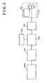
- Fig. 5 is a block diagram showing the case that the stabilizer actuator is connected to a motor drive circuit via a connector according to the first embodiment of the present invention.
- Fig. 6 is a diagram showing a system for an active roll restraint control according to the first embodiment of the present invention.
- Fig. 7 is a diagram showing a system of the active roll restraint control of Fig. 6 .
- Fig. 8 is a diagram showing a system of a motor control according to the first embodiment of the present invention.
- Fig. 9 is a flowchart showing a first failure judgment calculation according to the first embodiment of the present invention.
- Fig. 10 is a flowchart showing a second failure judgment calculation according to the first embodiment of the present invention.
- Fig. 13 is a graph showing characteristics of the stabilizer control device when the stabilizer control device assumes to be the failure after the generation of the roll angle of the vehicle and the vehicle travels maintaining the state.
- Fig. 14 is a graph showing characteristics when determining an initial value of a roll stiffness ratio for the front wheel.
- Fig. 15 is diagram showing a construction of a stabilizer actuator according to a second embodiment of the present invention.
- the stabilizer control device includes a stabilizer SBf for front wheel and a stabilizer SBr for rear wheel serving as torsion springs when the rolling motion is inputted to the vehicle.
- the stabilizer SBf for the front wheel and the stabilizer SBr for the rear wheel are constructed to variably control the respective torsional rigidity by stabilizer actuators FT, RT for restraining the vehicle body roll angle corresponding to the rolling motion of the vehicle body.
- a stabilizer control unit ECU 1 provided in an electronic control unit ECU controls the stabilizer actuators FT, RT.
- each wheel WHfr, WHfl, WHrr, WHrl is provided with each wheel speed sensor WSfr, WSfl, WSrr, WSrI: Front wheels WSfr, WSfl are steered by a EPS (Eelectric Power Steering).
- the wheel speed sensors WSfr, WSfl, WSrr, WSrl are connected to the electronic control unit ECU so that the pulse signals with the pulse number proportional to the wheel speed, that is, the rotational speed of each wheel, is inputted to the electronic control unit ECU.
- the electronic control unit ECU is connected to a steering angle sensor SA for detecting a steering angle ⁇ f of a steering wheel SW, a longitudinal acceleration sensor XG for detecting the longitudinal acceleration Gx of the vehicle, a lateral acceleration sensor YG for detecting the lateral acceleration Gy, and a yaw rate sensor YR for detecting the yaw rate Yr of the vehicle.
- the electronic control unit ECU includes the stabilizer control unit ECU1, a brake control unit ECU2, and a steering control unit ECU3.
- the control units ECU1-3 are connected to a communication bus via a communication unit including a CPU, a ROM, and a RAM for the communication respectively. Thus, the information used for each control system can be sent from other control system.
- the stabilizer SBf for the front wheel is halved into a stabilizer bar SBfr and a stabilizer bar SBfl.
- a first end of the stabilizer bar SBfr at the right is connected to a right front wheel.
- a first end of the stabilizer bar SBfl at the left is connected to a left front wheel.
- a second end of one of the stabilizer bar SBfr and the stabilizer bar SBfl is connected to a rotor RO of an electric motor M via a decelerator RD.
- a second end of the other of the stabilizer bar SBfr and the stabilizer bar SBfl is connected to a stator SR of the electric motor M.
- the stabilizer bar SBfr and the stabilizer bar SBfl are held at the vehicle body by holding means HLfr, HLfl.
- the electric motor M is energized, because the torsional force is generated relative to the stabilizer bar SBfr and the stabilizer bar SBfl to change the torsion spring characteristics of the stabilizer SBf for the front wheel on the surface, the roll stiffness of the vehicle body is controlled.
- the construction of the stabilizer actuator RT is likewise the construction of the stabilizer actuator FT.
- the electric motor M included in the stabilizer actuator FT at the stabilizer SBf for the front wheel is controlled to be driven by the stabilizer control unit ECU1.
- the stabilizer control unit ECU1 includes a relay drive circuit RC, a motor drive circuit MC, an electric current detection portion IS, a controller CT, and a constant voltage regulator.
- the driving electric current supplied from the motor drive circuit MC to the electric motor M is controlled by the controller CT.
- the driving electric current supplied from the motor drive circuit MC is detected by the electric current detection portion IS to be fed back to the controller CT along with a rotational angle signal of the electric motor M detected by a rotational angle detection means RS.
- the controller CT controls a roll restraint control, a motor servo control, and a failure judgment based on the signal including the steering angle ⁇ f by an operator and a vehicle motion state amount.
- the relay drive circuit RC and the motor drive circuit MC are controlled and a motor relay RY and the electric motor M are controlled.
- terminals of the electric motor M are short circuited by the motor relay RY. This generates the braking torque at the electric motor M using the counter electromotive force generated at the electric motor M. Accordingly, the sudden change of the vehicle body roll angle can be restrained.
- relays RLY1, RLY2, RLY3 configured to short-circuit terminals are provided between the three-phase electric motor M arranged to be connected in parallel with coils L1, L2, L3 of the electric motor M.
- the relays RLY1, RLY2, RLY3 are positioned to be able to short circuit each phase of a U-phase, a V-phase, and a W-phase at the electric motor M.
- One of the relays among the relays RLY1, RLY2, RLY3 may be omitted because all phases are short circuited by short circuiting any of two phases among three phases.
- the braking torque is obtained when the short circuit is attained between at least two phases out of the three phases, at least one motor relay is sufficient to serve for its function. In case the redundant is wanted as the system, it is preferable to position the motor relays between the all phases.
- a brush-less motor including three phases is applied for the electric motor M, the construction of the motor is not limited and the motor M including different phase numbers and a brush motor are applicable.
- the circuit of the relays RLY1, RLY2, RLY3 is short circuited. Because the relays RLY1, RLY2, RLY3 are the normal close type relays assuming to be short circuited at the non-energization state, the short circuit is formed at the coils L1, L2, L3 of the electric motor M. Thus, the electric current generated by the counter electromotive force generated by the rotation of the electric motor M flows in the short circuited relay circuit.
- the potential difference between the electric voltage of the ends of respective coils L1, L2, L3 of the electric motor M assumes to be absent so that the electric motor M operates to stop.
- the electric current by the counter electromotive force generated by the rotation of the electric motor M flows at the short circuit.
- the electric current by the counter electromotive force flows at the coils L1, L2, L3 to be consumed by the internal resistance of the circuit for gradually reducing the electric current value, which serves as the braking torque of the electric motor M functioning as applying the braking force to prevent the rotation by the external force (i.e., the vehicle body inertia force) relative to the electric motor M.
- the short circuit is formed by the motor relay RY including the relays RLY1, RLY2, RLY3, the braking torque is applied to the electric motor M by the counter electromotive force generated by the formation of the short circuit, and the vehicle body roll angle variation is restrained. Further, the desired deceleration relative to the electric motor M is performed so that the vehicle body roll angle variation includes the favorable characteristics.
- the opening and the closing of the short circuit of the relays RLY1, RLY2, RLY3 may be repeated periodically plural times and the timing for short circuiting each relay RLY1, RLY2, RLY3 and the operational time may be controlled in order to applied to the favorable patterns.
- the motor relay RY is short circuited immediately so that the electric voltage between each relay terminal assumes zero. Accordingly, the counter electromotive force is generated so that the braking torque is generated at the electric motor M to control the rotation of the electric motor M by the external force (i.e., the vehicle body inertia force).
- the external force i.e., the vehicle body inertia force
- the torsional action of the stabilizer is suddenly released when the failure is judged at a time T2 to stop the energization to the electric motor M is stopped.
- the vehicle body roll angle of the vehicle which is not applied with the stabilizer control device according to the embodiment of the present invention is suddenly diminished to provide the uncomfortable feeling to the operator.
- the stabilizer control device in case the failure is judged at the time T2, because the short circuit between the motor terminals is formed and the braking torque is applied to the electric motor M, the vehicle body roll angle gradually diminishes, which does not provide the uncomfortable feeling to the operator.
- the failure includes the failure of the power source system PW and the other failure.
- the failure of the power source system PW will be explained as follows. Even when the power is not supplied to the stabilizer actuator, the motor terminals have to be securely short-circuited.
- the normal close type relays short circuited at the non-energization state at which the electric power is not supplied is used for the relays RLY1, RLY2, RLY3 of Fig. 4 .
- each relay is driven from the closed position to the open position, the short circuit state between the motor terminals is canceled, and the energization to the electric motor M is conducted.
- the stabilizer actuator FT (or the stabilizer actuator RT) is connected to the motor drive circuit MC via a connector CN, as shown in Fig. 5 , it is preferable to position the motor relay RY at the electric motor M side relative to the connector CN in order to securely attain the short circuit state even when the connector of the motor relay RY is pulled away.
- the system of an active roll control shown in Fig. 5 will be explained referring to Fig. 6 .
- the information including the steering angle ⁇ f is detected by an operator's operation detection means M11, and the vehicle emotion state amount including the vehicle speed, the lateral acceleration, and the yaw rate is detected by a vehicle driving state detection means M12 at the steering operation by the operator.
- a vehicle active rolling moment target value for attaining the preferable rolling characteristics of the vehicle is calculated at a vehicle active rolling moment target value calculation portion at a vehicle active rolling moment target value calculation portion M13.
- the steering characteristic of the vehicle i.e., under-steer and over-steer
- the steering characteristic of the vehicle is judged based on the steering operation by the operator and the vehicle motion state amount at a vehicle behavior judging calculation portion M14.
- a target value of the roll stiffness ratio of the front wheels and the rear wheels is calculated in accordance with the calculated steering characteristics and the vehicle motions state at a front and rear wheels roll stiffness ratio target value calculation portion M15.
- a target value of the active rolling moment of the front wheels and the rear wheels is calculated based on the target value of the roll stiffness ratio and the active rolling moment at a front wheel and rear wheel active rolling moment target value calculation portion M16.
- the stabilizer actuator FT, RT at the front wheels and at the rear wheels is controlled based on the target values at an actuator servo control portion M17.
- the motor relay RY (shown in Fig. 5 ) is positioned between the terminals of the electric motor M for driving the actuator.
- the motor relay RY is controlled by a relay driving means M19.
- the relay driving means M19 is controlled from the open position to be the closed position for short circuiting between the relay terminals at the generation of the failure based on the judgment result of the failure judging means M18.
- the braking torque is applied to the electric motor M at the failure to restrain the sudden change of the vehicle body roll angle.
- An active rolling moment amount RMv used for restraining the rolling motion at the entire vehicle body is calculated based on the lateral acceleration Gy obtained from the signal from a lateral acceleration sensor YG, the lateral acceleration variation amount dGy attained by differentiating the lateral acceleration Gy with respect to time, the calculated lateral acceleration Gye calculated from the steering angle ⁇ f and the vehicle speed Vx, and the calculated lateral acceleration variation amount dGye attained by differentiating the calculated lateral acceleration Gye with respect to time at the vehicle active rolling moment target value calculation portion M13.
- the calculated lateral acceleration Gye is calculated as follows.
- Gye ( Vx 2 ⁇ ⁇ f ) / L ⁇ N ⁇ 1 + Kh ⁇ Vx 2
- L stands for a wheelbase
- N stand for a steering gear ratio
- Kh stands for a stability factor
- the active rolling moment Rmv to be applied to the entire vehicle for attaining the favorable rolling characteristics is obtained by a formula as follows.
- K1, K2, K3, K4 correspond to the control gain.
- the calculated lateral acceleration Gye and the calculated lateral acceleration variation amount dGye obtained from the steering angle ⁇ f and the vehicle speed Vx are considered.
- a target value of the roll stiffness ratio at front wheels and rear wheels is determined at the roll stiffness ratio target value calculation portion M15 for the front and rear wheels.
- Initial values Rsrfo, Rsrro of the roll stiffness ratio at the front wheel side and the rear wheel side are determined based on the vehicle speed Vx.
- the initial value Rsrfo of the roll stiffness ratio at the front wheel is determined to be high at the low vehicle speed and to be high at the high vehicle speed as shown in Fig. 14 .
- the initial value Rsrfo of the roll stiffness ratio at the front wheel is also determined to have a stronger under-steer tendency.
- the initial value Rsrro of the roll stiffness distribution ratio of the rear wheels is determined by subtracting the initial value Rsrfo of the roll stiffness ratio at the front wheel from one (i.e., 1-Rsrfo). Thereafter, a roll stiffness ratio correction value Rsra is calculated based on a yaw rate deviation ⁇ Yr calculated at the vehicle behavior judgment calculation portion M14.
- the yaw rate deviation ⁇ Yr is obtained by comparing an actual yaw rate Yr and a target yaw rate Yre calculated from the steering angle ⁇ f and the vehicle speed Vx for distinguishing the vehicle steering characteristics.
- the roll stiffness ratios are corrected so that the roll stiffness ratio at the front wheel side is declined and the roll stiffness ratio at the rear wheel side is increased.
- the roll stiffness is corrected so that the roll stiffness ratio at the front wheel side is increased and the roll stiffness ratio at the rear wheel side is declined.
- the active rolling moment target values Rmf and Rmr at the front wheel and the at the rear wheel are respectively determined based on the roll stiffness target value Rsrf at the front wheel and the roll stiffness ratio target value Rsrr at the rear wheel, and the vehicle active rolling moment target value Rmv at the active rolling moment target value calculation portion M16 for the front wheel and the rear wheel.
- the front wheel and the rear wheel active rolling moment target values, Rmf, Rmr are determined as shown in the following formulas.
- the torsional forcees to be generated at the stabilizer actuator FT for the front wheel and at the stabilizer actuator for the rear wheel RT are determined based on the active rolling moment target value Rmf for the front wheel and the on the active rolling moment target vale Rmr, thus to control the electric motor M.
- the electric motor M is controlled, for example, as shown in Fig, 8 .
- a target value of the motor output is calculated from the active rolling moment target value Rmf, Rmr at a motor output target value calculation portion M21.
- the obtained target value of the motor output is compared with the actual motor output to attain a motor output deviation at a motor output deviation calculation portion M22.
- a PWM output outputted to the electric motor M is determined based on the motor output deviation at a PWM output calculation portion M23 for controlling a switching element at the motor drive circuit MC.
- the sensor abnormality is judged when the inconsistency is generated between the vehicle state amounts at a predetermined relationship, and the abnormality flag is provided on the communication bus. For example, the failure is judged when the deviation between the lateral acceleration Gy and the yaw rate Yr multiplied by the vehicle speed Vx (i.e., the deviation between Gy and Yr .
- the current value Xn of the target value and the last value Xn-1 of the target value are not widely different.
- the increase of the absolute value of the deviation between the current value Xn of the target value and the last value Xn-1 of the target value shows the abnormality of the state amount for generating the deviation.
- the failure is judged at Step 105.
- the target value shown in Figs. 9-11 corresponds to the target value shown in Figs. 7-8 .
- the failure judgment calculation is initialized at Step 201.
- the target value Yt and the actual value Ya are read in at Step 202 and 203.
- the target value Yt and the actual value Ya are compared at Step 204.
- the failure is judged at Step 204 when the absolute value of the deviation between the target value Yt and the actual value Ya assumes equal to or greater than a predetermined value H2.
- the active roll control shown in Figs. 7-8 is basically conducted based on the deviation between the target value and the actual value. At the normal operation, the target value Yt and the actual value Ya are not widely different.
- the absolute value of the deviation between the target value Yt and the actual value Ya is increased due to the abnormality of the state amount for generating the target value Yt, the sensor for detecting the actual value Ya, and the calculation result, or the like.
- the failure is judged when the absolute value of the deviation between the target value Yt and the actual value Ya assumes equal to or greater than the predetermined value H2 at Step 205.
- the target value Yt and the actual value Ya correspond to the target value (the calculation value), the sensor value shown in Figs. 7-8 .
- the failure judgment calculation is initialized at Step 301.
- An actual value Za detected by the sensor is read in at Step 302.
- the actual value Za is compared with a predetermined value H3 at Step 303.
- the failure is judged when the actual value Za is equal to or greater than the predetermined value H3.
- the failure judgment is conducted when the overcurrent equal to or greater than the predetermined value is detected by the detecting of the motor drive electric current of the motor drive circuit MC of Fig. 3 .
- the actual value may have the top limitation value or may have the favorable value, or the like.
- the failure is judged at Step 304 when the rotational angle from a rotational angle detection means RS (shown in Fig. 3 ) assumes equal to or greater than a predetermined value, or equal to or less than a predetermined value H4 although the vehicle is at a predetermined turning state.
- a rotational angle detection means RS shown in Fig. 3
- Halved stabilizer bar SBfr, SBfl are positioned at ends of a stabilizer actuator SCA.
- the stabilizer bar SBfr, SBfl is supported by holding means HLfr, HLfl respectively.
- the stabilizer actuator SCA is connected to a suspension arm.
- An electric motor SM for providing the torsional rigidity is positioned on a shaft of one of the halved stabilizer bar, for example, the stabilizer bar SBfl.
- the electric motor SM includes a multi-polar brush-less motor and a hollow motor stator MS and a motor rotor MR positioned on the shaft of the stabilizer bar SBfl.
- the motor rotor MR includes a cylindrical member MH whose ends are supported by bearings. Multi-polar magnet is provided at the cylindrical member MH.
- the electric motor SM includes a rotational sensor RAS for detecting the shaft rotation of the stabilizer bar SBfl and SBfr approximate to the motor rotor MR.
- the rotational sensor RAS includes a magnet positioned in a ring configuration and include the same phase with the magnet of the motor rotor MR.
- the stabilizer actuator SCA includes a deceleration gear PGU including a Ferguson Mechanical Paradox including a sun gear, a plurality of planetary gears, and a plurality of ring gears for transmitting the driving force by the rotation of the electric motor SM after decelerating.
- the rotation of the electric motor SM is decelerated by the deceleration gear PGU to transmit the torsional force to the stabilizer bars SBfr, SBfl.
- the combination of the gears used for the deceleration gear PGU is determined considering the specification of the electric motor and the deceleration ratio of the gear. Accordingly, with the second embodiment of the present invention, the vehicle roll generated at the vehicle traveling can be restrained or reduced by controlling to actively provide the torsional rigidity relative to the stabilizer bar SBfr, SBfl by the stabilizer actuator SCA.
- the favorable roll characteristics can be maintained by short circuiting the motor relay when the electric power is not supplied to the electric motor and the failure of the stabilizer control device is judged without increasing the size of the actuator.
- the short circuit between the motor terminals is securely conducted.
- the desired vehicle body roll angle variation can be provided by controlling the short circuit time of the motor relay.
Landscapes
- Engineering & Computer Science (AREA)
- Mechanical Engineering (AREA)
- Vehicle Body Suspensions (AREA)
- Protection Of Generators And Motors (AREA)
Claims (4)
- Dispositif de contrôle pour barre antiroulis comportant :une paire de barres antiroulis (SBfr, SBfl) positionnée entre les roues droite et gauche d'un véhicule ;un actuateur (FT, RT) positionné entre ladite paire de barres antiroulis, l'actuateur comportant un moteur électrique (M) et générant une force de torsion à ladite paire de barres antiroulis;caractérisé en ce que le dispositif de contrôle de barre antiroulis comporte en outre :des moyens de contrôle (CT) pour contrôler le moteur électrique conformément à un état de braquage du véhicule ;un circuit d'entraînement de moteur (MC) contrôlé par les moyens de contrôle et relié aux bobines (L1, L2, L3) du moteur électrique par l'intermédiaire d'un connecteur (CN), le circuit d'entraînement de moteur délivrant un courant électrique d'entraînement au moteur électrique ;au moins un relais de moteur (RY, RLY1, RLY2, RLY3) positionné sur le côté du moteur électrique par rapport au connecteur et parallèle aux bobines du moteur électrique ; le relais du moteur étant court-circuité lorsqu'une énergie électrique est stoppée vers le moteur électrique pendant l'état de braquage du véhicule.
- Dispositif de contrôle pour barre antiroulis comportant :une paire de barres antiroulis (SBfr, SBf1) positionnée entre les roues droite et gauche d'un véhicule ;un actuateur (FT, RT) positionné entre ladite paire de barres antiroulis, l'actuateur comportant un moteur électrique (M) et générant une force de torsion à ladite paire de barres antiroulis;caractérisé en ce que le dispositif de contrôle de barre antiroulis comporte en outre :des moyens de contrôle (CT) pour contrôler le moteur électrique conformément à un état de braquage du véhicule ;un circuit d'entraînement de moteur (MC) contrôlé par les moyens de contrôle et relié aux bobines (L1, L2, L3) du moteur électrique par l'intermédiaire d'un connecteur (CN), le circuit d'entraînement de moteur délivrant un courant électrique d'entraînement au moteur électrique ;au moins un relais de moteur (RY, RLY1, RLY2, RLY3) positionné sur le côté du moteur électrique par rapport au connecteur et parallèle au nombre correspondant de bobines du moteur électrique ; etdes moyens d'estimation de panne (CT) pour estimer la panne du dispositif de contrôle de barre antiroulis pendant l'état de braquage du véhicule ; le relais de moteur étant court-circuité lorsque les moyens d'estimation de panne estiment la panne du dispositif de contrôle de barre antiroulis, et la panne comprenant celle du connecteur est écartée.
- Dispositif de contrôle de barre antiroulis selon la revendication 1-2, dans lequel le relais de moteur comprend un relais de type à fermeture normale pour former un court-circuit dans un état non excité.
- Dispositif de contrôle de barre antiroulis selon la revendication 1-2, dans lequel les moyens de contrôle contrôlent un temps de court-circuit du relais de moteur conformément à une variation de l'angle de roulis du corps du véhicule prédéterminé par rapport au véhicule.
Applications Claiming Priority (4)
| Application Number | Priority Date | Filing Date | Title |
|---|---|---|---|
| JP2003185600 | 2003-06-27 | ||
| JP2003185600 | 2003-06-27 | ||
| JP2003426396 | 2003-12-24 | ||
| JP2003426396A JP4438406B2 (ja) | 2003-06-27 | 2003-12-24 | スタビライザ制御装置 |
Publications (2)
| Publication Number | Publication Date |
|---|---|
| EP1491371A1 EP1491371A1 (fr) | 2004-12-29 |
| EP1491371B1 true EP1491371B1 (fr) | 2008-05-28 |
Family
ID=33422223
Family Applications (1)
| Application Number | Title | Priority Date | Filing Date |
|---|---|---|---|
| EP04014845A Expired - Lifetime EP1491371B1 (fr) | 2003-06-27 | 2004-06-24 | Régulation pour barre antiroulis |
Country Status (5)
| Country | Link |
|---|---|
| US (1) | US7322580B2 (fr) |
| EP (1) | EP1491371B1 (fr) |
| JP (1) | JP4438406B2 (fr) |
| CN (1) | CN100377952C (fr) |
| DE (1) | DE602004014069D1 (fr) |
Families Citing this family (45)
| Publication number | Priority date | Publication date | Assignee | Title |
|---|---|---|---|---|
| JP2006076377A (ja) * | 2004-09-08 | 2006-03-23 | Toyota Motor Corp | スタビライザ装置 |
| JP4455987B2 (ja) * | 2004-12-28 | 2010-04-21 | トヨタ自動車株式会社 | 車両用スタビライザシステム |
| JP4506522B2 (ja) * | 2005-03-16 | 2010-07-21 | トヨタ自動車株式会社 | サスペンションシステム |
| DE102005021673A1 (de) * | 2005-05-11 | 2006-11-16 | Bayerische Motoren Werke Ag | Geteilter elektromechanischer Kraftfahrzeugstabilisator mit Blockiereinrichtung und Verfahren zur Wankstabilisierung bei Ausfall oder Abschaltung des aktiven Kraftfahrzeugstabilisators |
| JP4240010B2 (ja) * | 2005-06-16 | 2009-03-18 | トヨタ自動車株式会社 | 車両用スタビライザシステム |
| JP4297085B2 (ja) * | 2005-06-16 | 2009-07-15 | トヨタ自動車株式会社 | 車両用スタビライザシステム |
| JP4404018B2 (ja) | 2005-06-16 | 2010-01-27 | トヨタ自動車株式会社 | 車両用スタビライザシステム |
| JP2007030575A (ja) * | 2005-07-25 | 2007-02-08 | Aisin Seiki Co Ltd | スタビライザ制御装置 |
| JP4770328B2 (ja) * | 2005-08-19 | 2011-09-14 | アイシン精機株式会社 | スタビライザ制御装置 |
| JP4341632B2 (ja) | 2006-02-21 | 2009-10-07 | トヨタ自動車株式会社 | スタビライザ制御装置 |
| JP4438763B2 (ja) * | 2006-03-20 | 2010-03-24 | トヨタ自動車株式会社 | 車両用スタビライザシステム |
| US7717410B2 (en) * | 2006-10-24 | 2010-05-18 | Wieslaw Julian Oledzki | Smooth non-linear springs, particularly smooth progressive rate steel springs, progressive rate vehicle suspensions and method |
| US7832739B2 (en) * | 2006-11-06 | 2010-11-16 | American Axle & Manufacturing, Inc. | Apparatus and method for coupling a disconnectable stabilizer bar |
| DE102007017242A1 (de) * | 2007-04-12 | 2008-10-16 | Dr. Ing. H.C. F. Porsche Aktiengesellschaft | Verfahren und Vorrichtung zur Wankstabilisierung eines Kraftfahrzeugs |
| DE102007040185A1 (de) | 2007-08-25 | 2009-02-26 | Bayerische Motoren Werke Aktiengesellschaft | Radaufhängung für Kraftfahrzeuge |
| US7887072B2 (en) * | 2008-10-09 | 2011-02-15 | American Axle & Manufacturing, Inc. | Stabilizer bar with disconnectable link |
| CA2801334C (fr) | 2010-06-03 | 2020-03-10 | Polaris Industries Inc. | Commande electronique du papillon des gaz |
| GB201014276D0 (en) * | 2010-08-26 | 2010-10-13 | Imp Innovations Ltd | Variable-geometry suspension apparatus and vehicle comprising such apparatus |
| DE102011002341A1 (de) | 2011-04-29 | 2012-10-31 | Benteler Automobiltechnik Gmbh | Verfahren zur Regelung und Steuerung eines semiaktiven Kraftfahrzeugstabilisators |
| JP2012253404A (ja) | 2011-05-31 | 2012-12-20 | Renesas Electronics Corp | 半導体装置 |
| DE102012107507B4 (de) * | 2012-08-16 | 2025-03-13 | Dr. Ing. H.C. F. Porsche Aktiengesellschaft | Stabilisatoranordnung für ein Fahrwerk eines Kraftfahrzeuges |
| US9205717B2 (en) | 2012-11-07 | 2015-12-08 | Polaris Industries Inc. | Vehicle having suspension with continuous damping control |
| DE102012110656B4 (de) * | 2012-11-07 | 2026-03-26 | Dr. Ing. H.C. F. Porsche Aktiengesellschaft | Stabilisatoranordnung für ein Fahrwerk eines Kraftfahrzeugs |
| DE102013223424B4 (de) * | 2013-07-17 | 2021-03-04 | Schaeffler Technologies AG & Co. KG | Verfahren für den Betrieb eines Kraftfahrzeugs zur Erkennung einer Überbeanspruchung eines Wankstabilisators |
| CN103568773A (zh) * | 2013-11-19 | 2014-02-12 | 浙江吉利汽车研究院有限公司 | 一种汽车的稳定杆装置 |
| CN107406094B (zh) | 2014-10-31 | 2020-04-14 | 北极星工业有限公司 | 用于控制车辆的系统和方法 |
| DE102015203907A1 (de) | 2015-03-05 | 2016-09-08 | Ford Global Technologies, Llc | Semi aktive Stabilisatoranordnung für ein Fahrwerk eines Fahrzeugs |
| DE102015203906A1 (de) | 2015-03-05 | 2016-09-08 | Ford Global Technologies, Llc | Semi-aktive Stabilisatoranordnung für ein Fahrwerk eines Fahrzeugs |
| DE202015101123U1 (de) | 2015-03-05 | 2015-03-13 | Ford Global Technologies, Llc | Semi aktive Stabilisatoranordnung für ein Fahrwerk eines Fahrzeugs |
| DE102016215004B4 (de) * | 2016-08-11 | 2018-12-27 | Schaeffler Technologies AG & Co. KG | Verfahren zum Betreiben eines elektrischen Stellmotors, Wankstabilisatoreinrichtung und Fahrzeug |
| US10618370B2 (en) * | 2016-09-02 | 2020-04-14 | Mando Corporation | Active roll stabilizer |
| CA3043481C (fr) | 2016-11-18 | 2022-07-26 | Polaris Industries Inc. | Vehicule a suspension reglable |
| JP6573082B2 (ja) * | 2017-04-03 | 2019-09-11 | トヨタ自動車株式会社 | 車両のロール制御装置 |
| US10406884B2 (en) | 2017-06-09 | 2019-09-10 | Polaris Industries Inc. | Adjustable vehicle suspension system |
| US10650620B2 (en) * | 2017-09-11 | 2020-05-12 | GM Global Technology Operations LLC | Systems and methods to determine abnormalities in a vehicle stabilizer system |
| JP7132703B2 (ja) * | 2017-09-12 | 2022-09-07 | 日立Astemo株式会社 | 車両運動状態推定装置、車両運動状態推定システム、車両運動制御装置および車両運動状態推定方法 |
| US10987987B2 (en) | 2018-11-21 | 2021-04-27 | Polaris Industries Inc. | Vehicle having adjustable compression and rebound damping |
| DE102019213280B4 (de) * | 2019-09-03 | 2023-03-30 | Zf Friedrichshafen Ag | Verfahren zum Betreiben eines verstellbaren Wankstabilisators |
| US12397878B2 (en) | 2020-05-20 | 2025-08-26 | Polaris Industries Inc. | Systems and methods of adjustable suspensions for off-road recreational vehicles |
| DE102020114570A1 (de) * | 2020-05-29 | 2021-12-02 | Bayerische Motoren Werke Aktiengesellschaft | Vorrichtung und Verfahren zum Betrieb eines Wankstabilisierungssystems |
| MX2022015902A (es) | 2020-07-17 | 2023-01-24 | Polaris Inc | Suspensiones ajustables y operacion de vehiculo para vehiculos recreativos todoterreno. |
| JP7288922B2 (ja) * | 2021-03-25 | 2023-06-08 | 本田技研工業株式会社 | 電動サスペンション装置 |
| GB2618367B (en) * | 2022-05-05 | 2024-07-31 | Jaguar Land Rover Ltd | Vehicle roll control |
| CN116001509B (zh) * | 2022-11-08 | 2023-09-19 | 江苏克瑞迪机车有限公司 | 一种便于调节的全地形车辆用的悬架及使用方法 |
| JP2025032496A (ja) * | 2023-08-28 | 2025-03-12 | トヨタ自動車株式会社 | サスペンション装置 |
Family Cites Families (11)
| Publication number | Priority date | Publication date | Assignee | Title |
|---|---|---|---|---|
| US4981309A (en) * | 1989-08-31 | 1991-01-01 | Bose Corporation | Electromechanical transducing along a path |
| US5028073A (en) * | 1990-01-08 | 1991-07-02 | General Electric Company | Dynamic vehicle suspension system including electronically commutated motor |
| US5441298A (en) * | 1993-10-22 | 1995-08-15 | Ford Motor Company | Apparatus for stabilizing an electric active suspension system upon interruption of the power supply |
| JP3161381B2 (ja) * | 1997-10-06 | 2001-04-25 | 株式会社豊田自動織機製作所 | 産業車両の揺動制御装置 |
| US6076837A (en) * | 1998-02-03 | 2000-06-20 | Ford Motor Company | Method and apparatus for improving quality of actuator motion in a vehicle active tilt control system |
| DE19846275A1 (de) * | 1998-06-25 | 1999-12-30 | Bosch Gmbh Robert | System und Verfahren zur Wankstabilisierung von Fahrzeugen |
| US6425585B1 (en) * | 1998-06-25 | 2002-07-30 | Robert Bosch Gmbh | Process and system for stabilizing vehicles against rolling |
| AU2002330900A1 (en) * | 2001-07-19 | 2003-03-03 | Stoneridge Control Devices, Inc. | Failsafe smart bar actuator |
| US6679504B2 (en) * | 2001-10-23 | 2004-01-20 | Liquidspring Technologies, Inc. | Seamless control of spring stiffness in a liquid spring system |
| DE10221716A1 (de) * | 2002-05-16 | 2003-11-27 | Bayerische Motoren Werke Ag | Regelsystem für ein Kraftfahrzeug mit Wankstabilisierung |
| DE10257211A1 (de) * | 2002-12-07 | 2004-06-24 | Bayerische Motoren Werke Ag | Geteilter elektromechanischer Kraftfahrzeugstabilisator und Verfahren zur Wankstabilisierung bei Ausfall oder Abschaltung des aktiven Kraftfahrzeugstabilisators |
-
2003
- 2003-12-24 JP JP2003426396A patent/JP4438406B2/ja not_active Expired - Fee Related
-
2004
- 2004-06-24 EP EP04014845A patent/EP1491371B1/fr not_active Expired - Lifetime
- 2004-06-24 US US10/874,536 patent/US7322580B2/en not_active Expired - Lifetime
- 2004-06-24 DE DE602004014069T patent/DE602004014069D1/de not_active Expired - Lifetime
- 2004-06-25 CN CNB2004100618373A patent/CN100377952C/zh not_active Expired - Fee Related
Also Published As
| Publication number | Publication date |
|---|---|
| JP2005035515A (ja) | 2005-02-10 |
| JP4438406B2 (ja) | 2010-03-24 |
| CN100377952C (zh) | 2008-04-02 |
| US7322580B2 (en) | 2008-01-29 |
| CN1576135A (zh) | 2005-02-09 |
| EP1491371A1 (fr) | 2004-12-29 |
| DE602004014069D1 (de) | 2008-07-10 |
| US20050023789A1 (en) | 2005-02-03 |
Similar Documents
| Publication | Publication Date | Title |
|---|---|---|
| EP1491371B1 (fr) | Régulation pour barre antiroulis | |
| US7311316B2 (en) | Stabilizer control apparatus | |
| US7384047B2 (en) | Stabilizer control apparatus | |
| EP1893425B1 (fr) | Systeme stabilisateur de vehicule | |
| US7501786B2 (en) | Stabilizer control apparatus | |
| JP4728363B2 (ja) | 操舵制御装置 | |
| JP2008137446A (ja) | 車両のロール剛性制御装置 | |
| JP4045445B2 (ja) | スタビライザ制御装置 | |
| JP4341632B2 (ja) | スタビライザ制御装置 | |
| US7301295B2 (en) | Stabilizer control device | |
| JP4294525B2 (ja) | スタビライザ制御装置 | |
| JP2005255012A (ja) | スタビライザ制御装置 | |
| WO2007040012A1 (fr) | Dispositif de commande de stabilisateur | |
| JP4457842B2 (ja) | 車輌のロール運動制御装置 | |
| WO2005049344A1 (fr) | Dispositif de controle de suspension | |
| JP2010052515A (ja) | 電磁式作動装置制御システム |
Legal Events
| Date | Code | Title | Description |
|---|---|---|---|
| PUAI | Public reference made under article 153(3) epc to a published international application that has entered the european phase |
Free format text: ORIGINAL CODE: 0009012 |
|
| AK | Designated contracting states |
Kind code of ref document: A1 Designated state(s): AT BE BG CH CY CZ DE DK EE ES FI FR GB GR HU IE IT LI LU MC NL PL PT RO SE SI SK TR |
|
| AX | Request for extension of the european patent |
Extension state: AL HR LT LV MK |
|
| 17P | Request for examination filed |
Effective date: 20050318 |
|
| AKX | Designation fees paid |
Designated state(s): DE FR GB |
|
| 17Q | First examination report despatched |
Effective date: 20061013 |
|
| GRAP | Despatch of communication of intention to grant a patent |
Free format text: ORIGINAL CODE: EPIDOSNIGR1 |
|
| GRAS | Grant fee paid |
Free format text: ORIGINAL CODE: EPIDOSNIGR3 |
|
| GRAA | (expected) grant |
Free format text: ORIGINAL CODE: 0009210 |
|
| AK | Designated contracting states |
Kind code of ref document: B1 Designated state(s): DE FR GB |
|
| REG | Reference to a national code |
Ref country code: GB Ref legal event code: FG4D |
|
| REF | Corresponds to: |
Ref document number: 602004014069 Country of ref document: DE Date of ref document: 20080710 Kind code of ref document: P |
|
| PLBE | No opposition filed within time limit |
Free format text: ORIGINAL CODE: 0009261 |
|
| STAA | Information on the status of an ep patent application or granted ep patent |
Free format text: STATUS: NO OPPOSITION FILED WITHIN TIME LIMIT |
|
| 26N | No opposition filed |
Effective date: 20090303 |
|
| PGFP | Annual fee paid to national office [announced via postgrant information from national office to epo] |
Ref country code: GB Payment date: 20130619 Year of fee payment: 10 |
|
| GBPC | Gb: european patent ceased through non-payment of renewal fee |
Effective date: 20140624 |
|
| PG25 | Lapsed in a contracting state [announced via postgrant information from national office to epo] |
Ref country code: GB Free format text: LAPSE BECAUSE OF NON-PAYMENT OF DUE FEES Effective date: 20140624 |
|
| REG | Reference to a national code |
Ref country code: FR Ref legal event code: PLFP Year of fee payment: 13 |
|
| REG | Reference to a national code |
Ref country code: FR Ref legal event code: PLFP Year of fee payment: 14 |
|
| REG | Reference to a national code |
Ref country code: FR Ref legal event code: PLFP Year of fee payment: 15 |
|
| PGFP | Annual fee paid to national office [announced via postgrant information from national office to epo] |
Ref country code: FR Payment date: 20220510 Year of fee payment: 19 Ref country code: DE Payment date: 20220505 Year of fee payment: 19 |
|
| REG | Reference to a national code |
Ref country code: DE Ref legal event code: R119 Ref document number: 602004014069 Country of ref document: DE |
|
| PG25 | Lapsed in a contracting state [announced via postgrant information from national office to epo] |
Ref country code: DE Free format text: LAPSE BECAUSE OF NON-PAYMENT OF DUE FEES Effective date: 20240103 |
|
| PG25 | Lapsed in a contracting state [announced via postgrant information from national office to epo] |
Ref country code: FR Free format text: LAPSE BECAUSE OF NON-PAYMENT OF DUE FEES Effective date: 20230630 |