EP1491388A2 - Elektrisch klappbarer Sitz - Google Patents
Elektrisch klappbarer Sitz Download PDFInfo
- Publication number
- EP1491388A2 EP1491388A2 EP04014646A EP04014646A EP1491388A2 EP 1491388 A2 EP1491388 A2 EP 1491388A2 EP 04014646 A EP04014646 A EP 04014646A EP 04014646 A EP04014646 A EP 04014646A EP 1491388 A2 EP1491388 A2 EP 1491388A2
- Authority
- EP
- European Patent Office
- Prior art keywords
- seat
- seat apparatus
- cushion
- link
- vehicle floor
- Prior art date
- Legal status (The legal status is an assumption and is not a legal conclusion. Google has not performed a legal analysis and makes no representation as to the accuracy of the status listed.)
- Withdrawn
Links
Images


Classifications
-
- B—PERFORMING OPERATIONS; TRANSPORTING
- B60—VEHICLES IN GENERAL
- B60N—SEATS SPECIALLY ADAPTED FOR VEHICLES; VEHICLE PASSENGER ACCOMMODATION NOT OTHERWISE PROVIDED FOR
- B60N2/00—Seats specially adapted for vehicles; Arrangement or mounting of seats in vehicles
- B60N2/24—Seats specially adapted for vehicles; Arrangement or mounting of seats in vehicles for particular purposes or particular vehicles
- B60N2/30—Non-dismountable or dismountable seats storable in a non-use position, e.g. foldable spare seats
- B60N2/3002—Non-dismountable or dismountable seats storable in a non-use position, e.g. foldable spare seats back-rest movements
- B60N2/3004—Non-dismountable or dismountable seats storable in a non-use position, e.g. foldable spare seats back-rest movements by rotation only
- B60N2/3009—Non-dismountable or dismountable seats storable in a non-use position, e.g. foldable spare seats back-rest movements by rotation only about transversal axis
- B60N2/3011—Non-dismountable or dismountable seats storable in a non-use position, e.g. foldable spare seats back-rest movements by rotation only about transversal axis the back-rest being hinged on the cushion, e.g. "portefeuille movement"
-
- B—PERFORMING OPERATIONS; TRANSPORTING
- B60—VEHICLES IN GENERAL
- B60N—SEATS SPECIALLY ADAPTED FOR VEHICLES; VEHICLE PASSENGER ACCOMMODATION NOT OTHERWISE PROVIDED FOR
- B60N2/00—Seats specially adapted for vehicles; Arrangement or mounting of seats in vehicles
- B60N2/02—Seats specially adapted for vehicles; Arrangement or mounting of seats in vehicles the seat or part thereof being movable, e.g. adjustable
- B60N2/0224—Non-manual adjustments, e.g. with electrical operation
- B60N2/02246—Electric motors therefor
- B60N2/02258—Electric motors therefor characterised by the mounting of the electric motor for adjusting the seat
-
- B—PERFORMING OPERATIONS; TRANSPORTING
- B60—VEHICLES IN GENERAL
- B60N—SEATS SPECIALLY ADAPTED FOR VEHICLES; VEHICLE PASSENGER ACCOMMODATION NOT OTHERWISE PROVIDED FOR
- B60N2/00—Seats specially adapted for vehicles; Arrangement or mounting of seats in vehicles
- B60N2/02—Seats specially adapted for vehicles; Arrangement or mounting of seats in vehicles the seat or part thereof being movable, e.g. adjustable
- B60N2/22—Seats specially adapted for vehicles; Arrangement or mounting of seats in vehicles the seat or part thereof being movable, e.g. adjustable the back-rest being adjustable
- B60N2/2213—Gear wheel driven mechanism
-
- B—PERFORMING OPERATIONS; TRANSPORTING
- B60—VEHICLES IN GENERAL
- B60N—SEATS SPECIALLY ADAPTED FOR VEHICLES; VEHICLE PASSENGER ACCOMMODATION NOT OTHERWISE PROVIDED FOR
- B60N2/00—Seats specially adapted for vehicles; Arrangement or mounting of seats in vehicles
- B60N2/24—Seats specially adapted for vehicles; Arrangement or mounting of seats in vehicles for particular purposes or particular vehicles
- B60N2/30—Non-dismountable or dismountable seats storable in a non-use position, e.g. foldable spare seats
- B60N2/3038—Cushion movements
- B60N2/3063—Cushion movements by composed movement
- B60N2/3065—Cushion movements by composed movement in a longitudinal-vertical plane
-
- B—PERFORMING OPERATIONS; TRANSPORTING
- B60—VEHICLES IN GENERAL
- B60N—SEATS SPECIALLY ADAPTED FOR VEHICLES; VEHICLE PASSENGER ACCOMMODATION NOT OTHERWISE PROVIDED FOR
- B60N2/00—Seats specially adapted for vehicles; Arrangement or mounting of seats in vehicles
- B60N2/24—Seats specially adapted for vehicles; Arrangement or mounting of seats in vehicles for particular purposes or particular vehicles
- B60N2/30—Non-dismountable or dismountable seats storable in a non-use position, e.g. foldable spare seats
- B60N2/3072—Non-dismountable or dismountable seats storable in a non-use position, e.g. foldable spare seats on a lower level of a multi-level vehicle floor
- B60N2/3075—Non-dismountable or dismountable seats storable in a non-use position, e.g. foldable spare seats on a lower level of a multi-level vehicle floor stowed in recess
-
- B—PERFORMING OPERATIONS; TRANSPORTING
- B60—VEHICLES IN GENERAL
- B60N—SEATS SPECIALLY ADAPTED FOR VEHICLES; VEHICLE PASSENGER ACCOMMODATION NOT OTHERWISE PROVIDED FOR
- B60N2/00—Seats specially adapted for vehicles; Arrangement or mounting of seats in vehicles
- B60N2/24—Seats specially adapted for vehicles; Arrangement or mounting of seats in vehicles for particular purposes or particular vehicles
- B60N2/30—Non-dismountable or dismountable seats storable in a non-use position, e.g. foldable spare seats
- B60N2/3088—Non-dismountable or dismountable seats storable in a non-use position, e.g. foldable spare seats characterised by the mechanical link
- B60N2/309—Non-dismountable or dismountable seats storable in a non-use position, e.g. foldable spare seats characterised by the mechanical link rods
Definitions
- the current invention relates to a vehicle seat apparatus. More particularly, the invention pertains to a structure whereby the vehicle seat apparatus can be stored within a concave storage compartment provided below the surface of a vehicle floor when the vehicle seat is unused.
- the vehicle seat apparatus includes a link mechanism for supporting a cushion as a seating portion of the seat on the vehicle floor. Such link mechanism limits the seat to be a retractable folded condition so that a user may move the seat within the concave storage compartment.
- the posture of the link mechanism is not determined until the seat apparatus is installed to the vehicle. Further, the seat apparatus needs to be fixed on the vehicle floor with bolts at a predetermined position to be moved freely. In this way, the structure of the known seat apparatus is very complicated.
- a seat apparatus comprising a seat back as a backrest portion, a seat cushion as a seating portion, a link mechanism for supporting the seat cushion on a vehicle floor, and a driving source for actuating the link mechanism to position the seat cushion between a seating position and a stored position, characterized in that the link mechanism is pivotally mounted on the vehicle floor for defining a posture thereof and fixing the link mechanism to the vehicle floor.
- the link mechanism is maintained at a predetermined position by stopping the driving device at a predetermined position.
- the seat apparatus can be kept in a predetermined posture before installed on the vehicle floor.
- Such seat apparatus being the predetermined posture can be easily installed on the floor by fitting holes thereof to be screwed with bolts to a preferable installed position on the floor, which can simplify the installing operation.
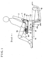
- a seat apparatus 1 according the current invention will be explained with reference to Fig. 1 through Fig.10.
- Fig. 1 through Fig.3 indicate a first embodiment according to the current invention.
- the seat apparatus 1 includes a seat back 2 and a seat cushion 3.
- cushion side frames 31 are provided to the seat cushion 3 at both right and left sides thereof in vehicle width direction as shown in Fig.2. Both cushion side frames 31 horizontally extend toward the front of the vehicle (leftward in Fig.1 and Fig.2). A front end portion of the left cushion side frames 31 is connected to a front end portion of the right cushion side frames 31 with a hollowed front connecting pipe 32.
- Each rear end portion of the cushion side frame 31 includes a projecting portion 31a extending upward, and a known angle adjustment mechanism 18 having a planetary gear mechanism 31b is attached to each projecting portion 31.
- the planetary gear mechanism provided to the right cushion side frame 31 interlocks with the planetary gear mechanism provided to the left cushion side frame 31.
- Back side frames 21 of the seat back 2 are attached to the angle adjustment mechanisms 18. Both angle adjusting mechanisms 18 are connected with an interlocking rod 24 for rotating in conjunction with each other.
- a second driving device 68 is attached to either one of the back side frames 21 for driving one angle adjustment mechanism 18.
- the second driving device 68 includes a motor and a decelerating mechanism, and such configuration is same as a first driving mechanism 61 (first driving source) as described later.
- the planetary gear mechanism of the angle adjusting mechanism 18 is actuated/rotated by a drive from the second driving device 68 (second driving source) for adjusting the angle of the seat back 2.
- the back side frames 21 provided on the right and left side of the seat back 2 in the vehicle width direction are connected with a upper connecting pipe 23 at the upper portions of the back side frames 21 for securing the strength thereof.
- the seat apparatus 1 includes link mechanisms 4 installed below the cushion side frames 31.
- the link mechanisms 4 include a paired front links 41 provided at the front of the seat apparatus 1 and a paired rear links 42 provided at the rear of the seat apparatus 1.
- one front link 41 is attached to the right cushion side frame 31, and the other front link 41 is attached to the left cushion side frame 31.
- Both front links 41 are provided at the outer side of the cushion side frames 31 in the vehicle width direction and connected each other with a rotation shaft 41a extending and penetrating through the hollowed front connecting pipe 32 provided between the front portions of the cushion side frames 31 so that the links are interlocked.
- one rear link 42 is attached to the right cushion side frame 31, and the other rear link 42 is attached to the left cushion side frame 31.
- Both rear links 42 are provided at the inner sides of the cushion side frames 31 in the vehicle width direction and connected with a rotation shaft 42a extending and penetrating through a hollowed rear connecting pipe 33 provided between the rear portions of the cushion side frames 31 so that the links are interlocked.
- the rear links 42 are rotatably supported at the cushion side frames 31 by the rotation shaft 42a penetrating through the rear connecting pipe 33.
- the rear links 42 extend approximately straight downward to be longer than the front links 41.
- Each front link 41 and each rear link 42 attached to the same cushion side frame 31 are connected with a supporting bracket 43 at the lower end of each link.
- the front link 41 is rotatably attached to the supporting bracket 43 with a rotating shaft 41b
- the rear link 42 is rotatably attached to the supporting bracket 43 with a rotating shaft 42b. In this configuration, the front link 41 and the rear link 42 are rotated at the same time even if the seat apparatus 1 is not installed on the vehicle floor 11.
- the supporting bracket 43 is molded to fit the stepped portion of the vehicle floor 11 as described later and fixed to the vehicle floor 11 with bolts (not shown) screwed into a hole 43a and a hole 43b. Such supporting bracket 43 installed in this manner can also reinforce the vehicle floor 11. Specifically, the supporting bracket 43 can reduce a deformation of the vehicle floor 11 when an excessive load transmits from the seat apparatus 1 to the vehicle floor 11 upon a collision.
- the first driving mechanism 61 is mounted to one of either right or left cushion side frame 31 at the inner side thereof in the vehicle width direction.
- the first driving mechanism 61 includes a motor 62 and a deceleration mechanism 63 for rotating a pinion 64 extending outwardly and penetrating through a hole (not shown) formed on the cushion side frame 31.
- the pinion 64 meshes with a gear 65 fixed to the rotating shaft 41a at the outer side of the cushion side frame 31 at which the first driving mechanism is attached.
- a drive from the first driving mechanism 61 transmits through the pinion 64 and the gear 65 to the front link 41, so that the front link is actuated/rotated relative to the cushion side frame 31.
- the rotation and positioning of the front link 41 relative to the cushion side frame 31 can be limited when the first driving mechanism 61 is not actuated.
- the link mechanism 4, which is pivotally mounted on the vehicle floor 11, has a so-called four link configuration, comprising the front link 41, the rear link 42, the cushion side frame 31 and the supporting bracket 43, and the link mechanisms 4 are provided at both right and left sides of the cushion side frame 31.
- the link mechanisms 4 provided both sides of the cushion side frame 31 are connected with the rotation shaft.
- the vehicle floor 11 includes a concave storage compartment 12 below the level of the vehicle floor 11 being normal height.
- the seat apparatus 1 is installed to the vehicle floor 11 as follows; the rear portion of the supporting bracket 43 at which the rear link 42 is supported by the rotation shaft 42b fits the bottom of the concave storage compartment 12, and the front portion of the supporting bracket 43 at which the front link 41 is supported by the rotation shaft 41b fits the surface of the vehicle floor 11.
- the front link 41 is rotated by the drive from the first driving mechanism 61 to be in a position shown in a chain double-dashed line in Fig.1 keeping the posture of the cushion side frame 31 approximately horizontally.
- the aforementioned first driving mechanism 61 and the second driving mechanism 68 are controlled by a control device 8 and an operation switch 9.
- the control device 8 and the operation switch 9 are wired to the first driving mechanism 61 and the second driving mechanism 68 as shown in Fig.4.
- the first driving mechanism 61 and the second driving mechanism 68 are actuated by operating the operation switch 9.
- An angle adjusting switch 9a of the operation switch 9 is operated by an occupant to adjust the angle of the seat back 2 to be seating position.
- the second driving mechanism 68 is actuated, the seat back 2 is tilted in front or rear direction, then the second driving mechanism 68 is stopped for maintaining the adjusted posture of the seat back 2.
- a storing switch 9b is moved to, for example, a "storing" side for opening the place where the seat apparatus 1 is located in seating position. Then, the first driving mechanism 61 is actuated by the controlling device 8, and the seat apparatus 1 is moved to the concave storage compartment 12 by the drive from the first driving mechanism 61, at the same time, the seat back 2 is rotated to be folded upon the seat cushion 3 upon the operation of the control device 8. In this way, the seat apparatus 1 is stored within the concave storage compartment 12 as shown in the chain double-dashed line in Fig.1. On the other hand, the storing switch 9b is moved to, for example, a "restore" side to restore the seat apparatus 1 within the concave storage compartment 12 to the original seating position.
- the seat apparatus 1 is kept in the predetermined posture because of the behavior of the link mechanism 4 while the seat apparatus 1 is moved between the seating position thereof and the stored position thereof so that the user can store the seat apparatus 1 within the concave storage compartment 12 or restore to the seating position without supporting the seat apparatus 1 manually.
- Such seat apparatus can be controlled even if the user is away from the seat apparatus 1. Further, there is no need to follow a complicated operational sequence to move the seat apparatus 1, as a result, the storing operation becomes simple and easy.
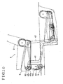
- Fig. 5 indicates a second embodiment according to the current invention.
- the seat apparatus 1 includes the seat back 2 as the backrest portion for a passenger and the seat cushion 3 as the seating portion.
- the seat back 2 being in seating position as shown in a solid line in Fig.5 is folded as shown in a chain double-dashed line and stored within the concave storage compartment 12 provided below the surface of the vehicle floor 11.
- the seat apparatus 1 includes the link mechanism 4 for supporting the seat cushion 3 to the vehicle floor 11 and the first driving device 61 for rotating the link mechanism 4.
- the first driving device 61 including the motor 62 is operated by the instruction from the operation switch 9.
- the seat apparatus 1 also includes the angle adjustment mechanism 18 for folding the seat back 2 on the seat cushion 3 and the second driving device 68 for rotating the angle adjustment mechanism 18.
- the second driving device 68 rotates the angle adjustment mechanism 18 corresponding to the rotation of the link mechanism 4 while the seat apparatus 1 is moved between the stored position thereof and the seating position thereof.
- Fig.5 indicates only one link mechanism 4 provided on one side of the seat apparatus 1 in the vehicle width direction; however, another link mechanism 4 is also provided at the other side of the seat apparatus 1.
- the first driving mechanism 61 is provided at either one of the right or left side of the seat apparatus 1 for rotating both link mechanisms 4 in conjunction with each other, at the same time, such configuration can secure the strength of the seat apparatus 1.
- the link mechanism 4 includes the front link 41and the rear link 42.
- the top end of the front link 41 is rotatably fixed to the seat cushion 3 with the rotation shaft 41a.
- the lower end of the front link 41 is rotatably fixed to a groove 11a formed on the vehicle floor 11 and being slightly lower than the vehicle flour 11 being normal height with the rotating shaft 41b.
- each front link 41 and rear link 42 are connected to the seat cushion 3 and the vehicle floor 11 with the rotation shafts, and such configuration is know as the four link mechanism.
- the seat apparatus 1 can be moved between the stored position thereof and the seating position thereof, where the seat cushion 3 is kept in horizontal.
- the gear 65 is fixed to one front link 41 for rotating integrally.
- a drive from the first driving device 61 transmits to the front link 41 through the gear 65 meshing with the pinion 64 of the first driving device 61 for rotating the front link 41 relative to the seat cushion 3 so that the link mechanism 4 can be rotated.
- a lock mechanism 5 is attached to the lower portion of the front link 41 being bended to fit to the vehicle floor 11.
- the lock mechanism 5 includes a housing 51 in which a latch 52 being rotatable relative to a shaft 52a and a pawl 53 being rotatable relative to a shaft 53a.
- the latch 52 includes a hook portion 52d being engagable with a striker 56 fixed to the groove 11a of the vehicle floor 11.
- An engaging portion 53b formed at the pawl 53 is engaged with a engaging portion 52b formed at the latch 52 as shown in Fig.6 to limit the rotation of the latch 52, as a result, the engagement between the hook portion 52d and the striker 56 is maintained so that the link mechanism 4 is fixed at the vehicle floor 11.
- the engagement between the latch 52 and the pawl 53 is maintained by a force of an extended spring 54 provided between a pin 52c mounted to a side surface of the latch 52 and a pin 53c mounted to a side surface of the pawl 53.
- a movable end 57a of an operating cable 57 is attached to the pin 53c of the pawl 53, and the other end of the operating cable 57 is attached to the housing 51.
- the seat apparatus 1 may included another driving device for folding the seat back 2, for moving the seat cushion 3 and for releasing the lock mechanism 5.
- Such driving device may be automatically operated by an operator using a control device such as a remote controller.
- a third embodiment according to the current invention is indicated in Fig.7.
- the seat apparatus 1 in the third embodiment also includes the four link mechanism comprising the front link 41, the rear link 42, the seat cushion 3 and the vehicle floor 11, however, the aforementioned lock mechanism 5 is mounted on the rear link 43 for engaging with the striker 56 fixed within the groove 11a of the vehicle floor 11.
- the link mechanism 4 according to the third embodiment includes same structure as the link mechanism 4 according to the second embodiment, wherein at least two links are connected each other to maintain the posture of the link mechanism 4 when the seat apparatus 1 is in seating position.
- FIG.8 A fourth embodiment according to the current invention is shown in Fig.8.
- the rear link 42 includes a lever portion 42c being projecting upwardly from the rotation shaft 42a, and the upper end of the lever portion 42c is rotatably connected to one end of a connecting link 44 provided between the lever portion 42c and a bracket 70.
- the other end of the connecting link 44 is connected to the bracket 70.
- the bracket 70 is rotatably supported to the rotation shaft 41a mounted on the upper end of the front link and extending vertically downward.
- the bracket 70 houses the lock mechanism 5 at the lower end thereof, and such lock mechanism 5 includes the latch 52 and the pawl 53 as mentioned above, wherein the latch 52 is engagable with the striker 56 provided on the groove 11a.
- the seat apparatus 1 according to the fourth embodiment also includes the fourth link mechanism, and the seat cushion 3 and the vehicle floor 11 are locked by the bracket 4 fixed with the lock mechanism 5. On this account, the posture of the link mechanism 4 is maintained in seating position.
- the posture of the link mechanism 4 can be maintained by locking at least two elements of the link mechanism 4 each other.
- the configuration of the link mechanism 4 is not limited to such embodiments, specifically, the lock mechanism 5 and the striker 56 may be provided between any elements of the link mechanism 4.
- the seat apparatus 1 includes the motor 62 for moving the seat apparatus 1 between the seating position and the stored position. Specifically, the motor 62 moves the seat apparatus 1 to the seating positions shown in solid lines in Fig.5, 7 and 8, where the lock mechanism 5 is surely engaged with the vehicle floor 11. Further, an elastic stopper (not shown) may be attached, for example, between the latch and the striker to prevent clattering of the seat apparatus being seating position. In such configuration, the motor 62 rotates for outputting a drive enough to push the seat apparatus 1 to the elastic stopper and secure the engaging condition of the lock mechanism at any time.
- the seat apparatus 1 includes the lock mechanism 5 to support the seat apparatus 1 at the seating position; however, another lock mechanism may be provided to the seat apparatus 1 for support the seat apparatus 1 at the stored position so that clattering of the stored seat can be prevented.
- the lock mechanism 5 includes a projecting portion 53d at the pawl 53, and a detecting sensor 81 including a switch mechanism is attached to the bracket 70 to be engaged or disengaged relative to the projecting portion 53d.
- the detecting sensor 81 outputs an electrical "on” signal when the lock mechanism 5 is engaged with the striker 56, and the detecting sensor 81 is engaged with the projecting portion 53d.
- the sensor outputs an electrical "off” signal when the lock mechanism 5 is disengaged from the striker 56, and the detecting sensor 81 is disengaged from the projecting portion 53d.
- the detecting sensor 81 directly detecting the locking condition of the lock mechanism 5 assures the engaging condition of the seat apparatus 1 more firmly.
- Such signals from the detecting sensor 81 can be used as inputs for the control device for controlling the movement of the seat apparatus 1 automatically.
- the seat apparatus 1 according to the sixth embodiment includes the aforementioned detecting sensor 81 and another detecting sensor 82 (second detecting sensor).
- the second detecting sensor 82 is mounted on the seat cushion 3 and being engagable with a projecting portion 43c formed at the bracket 70.
- the second detecting sensor 2 outputs "on" signal when the bracket 70 moves to be at a predetermined position relative to the seat cushion 3.
- the seat apparatus 1 can be controlled to be locked more precisely by detecting the position of the seat apparatus 1 based on the "on” and “off” signal from the detecting sensor 82.
- the detecting sensor 82 can be mounted to the seat apparatus 1 being manually controlled. Specifically, with the detecting sensor 82, the seat apparatus 1 can be locked at the predetermined seating position even if the seat apparatus 1 is not rotated by the motor.
Landscapes
- Engineering & Computer Science (AREA)
- Aviation & Aerospace Engineering (AREA)
- Transportation (AREA)
- Mechanical Engineering (AREA)
- Seats For Vehicles (AREA)
Applications Claiming Priority (4)
| Application Number | Priority Date | Filing Date | Title |
|---|---|---|---|
| JP2003179628A JP2005014670A (ja) | 2003-06-24 | 2003-06-24 | シート装置 |
| JP2003179628 | 2003-06-24 | ||
| JP2003185599 | 2003-06-27 | ||
| JP2003185599A JP2005014843A (ja) | 2003-06-27 | 2003-06-27 | シート装置 |
Publications (2)
| Publication Number | Publication Date |
|---|---|
| EP1491388A2 true EP1491388A2 (de) | 2004-12-29 |
| EP1491388A3 EP1491388A3 (de) | 2005-10-19 |
Family
ID=33422195
Family Applications (1)
| Application Number | Title | Priority Date | Filing Date |
|---|---|---|---|
| EP04014646A Withdrawn EP1491388A3 (de) | 2003-06-24 | 2004-06-23 | Elektrisch klappbarer Sitz |
Country Status (2)
| Country | Link |
|---|---|
| US (1) | US20050006920A1 (de) |
| EP (1) | EP1491388A3 (de) |
Cited By (4)
| Publication number | Priority date | Publication date | Assignee | Title |
|---|---|---|---|---|
| FR2896459A1 (fr) * | 2006-01-25 | 2007-07-27 | Faurecia Sieges Automobile | Systeme d'escamotage de siege de vehicule |
| DE202007001735U1 (de) | 2007-02-07 | 2008-06-19 | Brose Fahrzeugteile Gmbh & Co. Kommanditgesellschaft, Coburg | Fahrzeugklappsitz |
| CN103144558A (zh) * | 2011-12-07 | 2013-06-12 | 现代自动车株式会社 | 用于多功能车辆的后座椅的存储装置 |
| EP3680126A1 (de) * | 2019-01-08 | 2020-07-15 | Toyota Boshoku Kabushiki Kaisha | Fahrzeugsitzvorrichtung |
Families Citing this family (16)
| Publication number | Priority date | Publication date | Assignee | Title |
|---|---|---|---|---|
| JP4494314B2 (ja) * | 2005-08-30 | 2010-06-30 | アイシン精機株式会社 | シート装置 |
| US7600801B2 (en) * | 2006-12-20 | 2009-10-13 | Globe Motors, Inc. | Seat storage actuator |
| JP5341914B2 (ja) * | 2008-12-26 | 2013-11-13 | シロキ工業株式会社 | 格納式車両用シート |
| DE112011103970B4 (de) | 2010-11-30 | 2017-06-22 | Ts Tech Co., Ltd. | Automobilklappsitzvorrichtung |
| CA2937735A1 (en) * | 2014-01-31 | 2015-08-06 | Bombardier Recreational Products Inc. | Off-road wheeled side-by-side vehicle |
| JP6780454B2 (ja) * | 2016-11-09 | 2020-11-04 | トヨタ紡織株式会社 | 乗物シート用バックフレーム |
| DE102017215913A1 (de) | 2017-09-08 | 2019-03-14 | Brose Fahrzeugteile Gmbh & Co. Kg, Coburg | Fahrzeugsitz mit einem um eine einzige Schwenkachse schwenkbaren Sitzteil |
| DE102017215914A1 (de) * | 2017-09-08 | 2019-03-14 | Brose Fahrzeugteile Gmbh & Co. Kg, Coburg | Fahrzeugsitz mit einem schwenkbaren Sitzteil und einer Funktionseinheit |
| WO2021187496A1 (ja) * | 2020-03-17 | 2021-09-23 | テイ・エス テック株式会社 | 乗物用シート |
| US11904732B2 (en) | 2020-11-09 | 2024-02-20 | Ford Global Technologies, Llc | Vehicular system capable of adjusting a passenger compartment from a first arrangement to a child care arrangement |
| US11772517B2 (en) | 2020-11-09 | 2023-10-03 | Ford Global Technologies, Llc | Vehicular system capable of adjusting a passenger compartment from a child seat arrangement to a second arrangement |
| US11731535B2 (en) | 2020-11-09 | 2023-08-22 | Ford Global Technologies, Llc | Vehicular system capable of adjusting a passenger compartment from a child care arrangement to a second arrangement |
| US11772520B2 (en) | 2020-11-09 | 2023-10-03 | Ford Global Technologies, Llc | Remote notification and adjustment of a passenger compartment arrangement |
| US12257932B2 (en) | 2020-11-09 | 2025-03-25 | Ford Global Technologies, Llc | Exterior imager utilized in adjusting a passenger compartment arrangement |
| US12077068B2 (en) | 2020-11-09 | 2024-09-03 | Ford Global Technologies, Llc | Authorization-based adjustment of passenger compartment arrangement |
| US11772519B2 (en) | 2020-11-09 | 2023-10-03 | Ford Global Technologies, Llc | Vehicular system capable of adjusting a passenger compartment from a first arrangement to a child seat arrangement |
Family Cites Families (18)
| Publication number | Priority date | Publication date | Assignee | Title |
|---|---|---|---|---|
| JP4019456B2 (ja) * | 1997-07-31 | 2007-12-12 | マツダ株式会社 | 車両用シート構造 |
| US5890758A (en) * | 1997-08-19 | 1999-04-06 | Chrysler Corporation | Seat assembly for a motor vehicle retractable below the vehicle floor |
| US6234553B1 (en) * | 1998-10-02 | 2001-05-22 | Johnson Controls Technology Company | Flexible seat system |
| JP3635292B2 (ja) * | 1999-08-10 | 2005-04-06 | トヨタ紡織株式会社 | 車両用リヤシート |
| US6270141B2 (en) * | 1999-11-22 | 2001-08-07 | Visteon Global Technologies, Inc. | Power assisted seat folding mechanism |
| US6644730B2 (en) * | 2000-06-08 | 2003-11-11 | Takashimaya Nippatsu Kogyo Co., Ltd. | Storage type seat for automobile and seat storage structure |
| US6499787B2 (en) * | 2000-07-26 | 2002-12-31 | Lear Corporation | Collapsible vehicle seat assemblies |
| US6572171B1 (en) * | 2000-11-17 | 2003-06-03 | General Motors Corporation | Motor vehicle seat system |
| CA2364711C (en) * | 2000-12-11 | 2009-02-03 | Magna Seating Systems Inc. | Fold flat seat assembly |
| JP4431800B2 (ja) * | 2000-12-29 | 2010-03-17 | テイ・エス テック株式会社 | インターロック装置並びに折畳み自在シート |
| US6676198B2 (en) * | 2001-12-07 | 2004-01-13 | Faurecia Automotive Seating Canada Limited | Mounting system and vehicle seat assembly including the same |
| KR20030074162A (ko) * | 2002-03-14 | 2003-09-19 | 마쯔다 가부시키가이샤 | 차량용 시트 장치 |
| JP3706093B2 (ja) * | 2002-09-04 | 2005-10-12 | 本田技研工業株式会社 | 車両の後部構造 |
| US6746083B2 (en) * | 2002-09-27 | 2004-06-08 | Lear Corporation | Vehicle seat assembly |
| JP2004196163A (ja) * | 2002-12-19 | 2004-07-15 | Aisin Seiki Co Ltd | シート装置 |
| EP1575800B1 (de) * | 2002-12-26 | 2009-08-26 | Honda Motor Co., Ltd. | Elektrisches verstausystem für fahrzeugsitze |
| JP4269714B2 (ja) * | 2003-02-25 | 2009-05-27 | アイシン精機株式会社 | シート装置 |
| DE602004010372T2 (de) * | 2003-02-25 | 2008-11-13 | Intier Automotive Inc., Newmarket | Sitzanordnung mit einem kraftrefraktionssystem für eine verstauung im boden |
-
2004
- 2004-06-23 EP EP04014646A patent/EP1491388A3/de not_active Withdrawn
- 2004-06-23 US US10/873,227 patent/US20050006920A1/en not_active Abandoned
Cited By (7)
| Publication number | Priority date | Publication date | Assignee | Title |
|---|---|---|---|---|
| FR2896459A1 (fr) * | 2006-01-25 | 2007-07-27 | Faurecia Sieges Automobile | Systeme d'escamotage de siege de vehicule |
| DE202007001735U1 (de) | 2007-02-07 | 2008-06-19 | Brose Fahrzeugteile Gmbh & Co. Kommanditgesellschaft, Coburg | Fahrzeugklappsitz |
| EP1955891A2 (de) | 2007-02-07 | 2008-08-13 | Brose Fahrzeugteile GmbH & Co. Kommanditgesellschaft, Coburg | Fahrzeugklappsitz |
| CN103144558A (zh) * | 2011-12-07 | 2013-06-12 | 现代自动车株式会社 | 用于多功能车辆的后座椅的存储装置 |
| CN103144558B (zh) * | 2011-12-07 | 2016-09-28 | 现代自动车株式会社 | 用于多功能车辆的后座椅的存储装置 |
| EP3680126A1 (de) * | 2019-01-08 | 2020-07-15 | Toyota Boshoku Kabushiki Kaisha | Fahrzeugsitzvorrichtung |
| US11065985B2 (en) | 2019-01-08 | 2021-07-20 | Toyota Boshoku Kabushiki Kaisha | Vehicle seat device |
Also Published As
| Publication number | Publication date |
|---|---|
| EP1491388A3 (de) | 2005-10-19 |
| US20050006920A1 (en) | 2005-01-13 |
Similar Documents
| Publication | Publication Date | Title |
|---|---|---|
| EP1491388A2 (de) | Elektrisch klappbarer Sitz | |
| US7063368B2 (en) | Electric vehicle seat stowing structure | |
| EP2261078B1 (de) | Vorrichtung zur verhinderung von fehlerhafter bedienung und umklappbarer sitz für ein fahrzeug | |
| EP1944192B1 (de) | Sitz | |
| JP5291373B2 (ja) | 誤操作防止装置及び車両用格納シート | |
| JP5746336B2 (ja) | 電気機械プッシュボタン車両座席作動機構 | |
| CN100434307C (zh) | 用于车辆座椅的电动收纳系统 | |
| WO2006104288A1 (ja) | 自動車用シ-トの高さ調整装置 | |
| US7472963B2 (en) | Recliner lever assembly for a front seat of a vehicle | |
| US8511750B2 (en) | Vehicle seat device | |
| CN107962986B (zh) | 动力提升和调角器释放/折叠装置 | |
| CN104039590B (zh) | 锁定和斜度调整组件 | |
| JP4720394B2 (ja) | 車両用シート装置 | |
| CN101474984B (zh) | 安全带装置 | |
| JP4566152B2 (ja) | 車両用シート装置 | |
| CN1576092B (zh) | 车辆用座椅的电动收纳系统 | |
| JP4517882B2 (ja) | 車両用シート | |
| JP2006282019A (ja) | 自動車用シートの高さ調整装置 | |
| JP4517883B2 (ja) | 車両用シート | |
| JP2005014843A (ja) | シート装置 | |
| JPH0633538U (ja) | リクライニングシート | |
| JP2006315623A (ja) | 車両用シート | |
| JP4622772B2 (ja) | 車両用シート装置 | |
| JP2000025502A (ja) | シートリフター構造 | |
| JP4278496B2 (ja) | 車両のシート構造 |
Legal Events
| Date | Code | Title | Description |
|---|---|---|---|
| PUAI | Public reference made under article 153(3) epc to a published international application that has entered the european phase |
Free format text: ORIGINAL CODE: 0009012 |
|
| AK | Designated contracting states |
Kind code of ref document: A2 Designated state(s): AT BE BG CH CY CZ DE DK EE ES FI FR GB GR HU IE IT LI LU MC NL PL PT RO SE SI SK TR |
|
| AX | Request for extension of the european patent |
Extension state: AL HR LT LV MK |
|
| PUAL | Search report despatched |
Free format text: ORIGINAL CODE: 0009013 |
|
| AK | Designated contracting states |
Kind code of ref document: A3 Designated state(s): AT BE BG CH CY CZ DE DK EE ES FI FR GB GR HU IE IT LI LU MC NL PL PT RO SE SI SK TR |
|
| AX | Request for extension of the european patent |
Extension state: AL HR LT LV MK |
|
| RIC1 | Information provided on ipc code assigned before grant |
Ipc: 7B 60N 2/015 B Ipc: 7B 60N 2/30 B Ipc: 7B 60N 2/22 B Ipc: 7B 60N 2/02 A |
|
| 17P | Request for examination filed |
Effective date: 20051202 |
|
| AKX | Designation fees paid |
Designated state(s): DE FR GB TR |
|
| STAA | Information on the status of an ep patent application or granted ep patent |
Free format text: STATUS: THE APPLICATION IS DEEMED TO BE WITHDRAWN |
|
| 18D | Application deemed to be withdrawn |
Effective date: 20080103 |