EP1491710A2 - Volet roulant - Google Patents
Volet roulant Download PDFInfo
- Publication number
- EP1491710A2 EP1491710A2 EP04014913A EP04014913A EP1491710A2 EP 1491710 A2 EP1491710 A2 EP 1491710A2 EP 04014913 A EP04014913 A EP 04014913A EP 04014913 A EP04014913 A EP 04014913A EP 1491710 A2 EP1491710 A2 EP 1491710A2
- Authority
- EP
- European Patent Office
- Prior art keywords
- slat
- slats
- condition
- fin
- longitudinal
- Prior art date
- Legal status (The legal status is an assumption and is not a legal conclusion. Google has not performed a legal analysis and makes no representation as to the accuracy of the status listed.)
- Withdrawn
Links
- 230000000295 complement effect Effects 0.000 claims description 9
- 239000003351 stiffener Substances 0.000 claims description 5
- 239000007769 metal material Substances 0.000 claims description 3
- 239000006260 foam Substances 0.000 claims description 2
- 239000011810 insulating material Substances 0.000 claims description 2
- 230000013011 mating Effects 0.000 claims description 2
- 239000002184 metal Substances 0.000 claims description 2
- 230000007246 mechanism Effects 0.000 description 7
- 229910000831 Steel Inorganic materials 0.000 description 3
- 239000010959 steel Substances 0.000 description 3
- 239000000428 dust Substances 0.000 description 2
- 238000009434 installation Methods 0.000 description 2
- 238000012423 maintenance Methods 0.000 description 2
- 238000004804 winding Methods 0.000 description 2
- 230000004888 barrier function Effects 0.000 description 1
- 230000008878 coupling Effects 0.000 description 1
- 238000010168 coupling process Methods 0.000 description 1
- 238000005859 coupling reaction Methods 0.000 description 1
- 238000000605 extraction Methods 0.000 description 1
- 238000003780 insertion Methods 0.000 description 1
- 230000037431 insertion Effects 0.000 description 1
- 238000009413 insulation Methods 0.000 description 1
- 238000004519 manufacturing process Methods 0.000 description 1
- 239000000463 material Substances 0.000 description 1
- 238000000034 method Methods 0.000 description 1
- 230000010355 oscillation Effects 0.000 description 1
- 230000002441 reversible effect Effects 0.000 description 1
- XLYOFNOQVPJJNP-UHFFFAOYSA-N water Substances O XLYOFNOQVPJJNP-UHFFFAOYSA-N 0.000 description 1
Images




Classifications
-
- E—FIXED CONSTRUCTIONS
- E06—DOORS, WINDOWS, SHUTTERS, OR ROLLER BLINDS IN GENERAL; LADDERS
- E06B—FIXED OR MOVABLE CLOSURES FOR OPENINGS IN BUILDINGS, VEHICLES, FENCES OR LIKE ENCLOSURES IN GENERAL, e.g. DOORS, WINDOWS, BLINDS, GATES
- E06B9/00—Screening or protective devices for wall or similar openings, with or without operating or securing mechanisms; Closures of similar construction
- E06B9/02—Shutters, movable grilles, or other safety closing devices, e.g. against burglary
- E06B9/08—Roll-type closures
- E06B9/11—Roller shutters
- E06B9/15—Roller shutters with closing members formed of slats or the like
-
- E—FIXED CONSTRUCTIONS
- E06—DOORS, WINDOWS, SHUTTERS, OR ROLLER BLINDS IN GENERAL; LADDERS
- E06B—FIXED OR MOVABLE CLOSURES FOR OPENINGS IN BUILDINGS, VEHICLES, FENCES OR LIKE ENCLOSURES IN GENERAL, e.g. DOORS, WINDOWS, BLINDS, GATES
- E06B9/00—Screening or protective devices for wall or similar openings, with or without operating or securing mechanisms; Closures of similar construction
- E06B9/56—Operating, guiding or securing devices or arrangements for roll-type closures; Spring drums; Tape drums; Counterweighting arrangements therefor
- E06B9/58—Guiding devices
Definitions
- the present invention relates to roller shutters for buildings and particularly it refers to a roller shutter device of burglar-resistant type and provided with shading fins, each thereof rotating on its axis.
- roller shutter devices constituted by slats sideways sliding along suitable vertical guides, between a shut condition and an open condition, by unwinding and winding round a roller.
- the slats can swivel or partially rotate on respective axes, assuring a partial and adjustable opening, likewise to the venetian blinds.
- the rotation is carried out by means of suitable mechanisms that are integral with the slats, with which said mechanisms translate when they are moved.
- a drawback of said known roller shutters with swiveling slats consists in that they comprise many components and they include mechanisms for moving the slats which are complex and require long times and skilled labour for their manufacturing, assemblage and installation.
- An object of the present invention is to propose a roller shutter device provided with rotating shading fin elements and constituted by a small number of components, which can be easily manufactured and assembled.
- Further object is to propose a device having a safe and reliable operation, requiring a minimal maintenance and guarantying a high resistance against the attempts of burglary and effraction, in any operational condition.
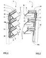
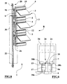
- numeral 1 indicates a roller shutter device provided with a plurality of slats 2, sideways sliding between two uprights 30 between an opening condition of said device, in which the slats 2 are wound round a revolving shaft and a closing condition, in which the slats 2 are partially or totally unwound from said revolving shaft.
- Each upright 30 consists of a tubular hollow section bar provided with a longitudinal opening 30a, which is almost entirely engaged by the ends of each slat 2, in order to reduce the clearance therebetween, that is to say to minimize the passage of light and/or dust and/or rain through said opening 30a.
- slats 2 comprise hooking means 7 fit to slidingly bear against abutment surfaces 30b of respective upright 30 in order to prevent the slat 2 from coming out from said upright 30, both accidentally and in consequence of attempts of burglary and effraction.
- each slat 2 is constituted by a fin element 3, two support elements, first 4 and second 5 and two link elements 6.
- the fin element 3 has an extended and flat shape, is rotatably on a respective longitudinal axis and is coupled to adjacent fin elements 3 of respective slats 2 at one or both side edges thereof by rotating means 20.
- the fin elements 3 in the closing condition of device 1 are rotated by rotating means 20 between a shut condition T and a rotated condition R, in which the fin elements 3 are respectively almost coplanar and rotated with respect to the uprights 30.
- the support elements, first 4 and second 5 have a prismatic and extended shape and are positioned parallel at a prearranged distance.
- Said support element 4, 5, at the respective side ends, are rotatably and removably connected by corresponding link elements 6, having a prismatic and extended shape as well, in such a way to form a kind of quadrangular frame, whose central opening thus can be closed by the fin element 3.
- Each link element 6 has side portions 6a fit for mating the edges of the longitudinal opening 30a of the corresponding upright 30 to minimize the opening inside the upright 30.
- the width of opening 30a is between 1 and 4 mm bigger than the width of the cross section of each link element 6 or than the distance between opposed side portions 6a of the latter.
- each slat 2 are fixed to the corresponding link elements 6 and, in the preferred embodiment, they substantially consist of a couple of stop protuberances 7, approximately "L" shaped, which can slide against abutment surfaces 30b carried out in each upright 30, near the longitudinal opening 30a.
- Said protrusions 7 prevent each link element 6 from coming out unintentionally or by force from the inside of upright 30, so guaranteeing a high safety degree with respect to burglary and effraction, both when the fin elements 3 are in rotated condition R and the device is in the full closing condition and when the fin elements 3 are in the shut condition T and the shutter device is partially wound.
- each first support element 4 has respectively a first seat 8 and a shaped protrusion 10.
- the latter in an assemblage condition of device 1, is rotatably and removably housed in a second seat 26 of complementary shape, carried out on a longitudinal edge of a second element 4.
- the first seat 8 rotatably and removably accommodates a respective longitudinal and complementary shaped edge 9 of the respective fin element 3.
- the first seat 8 and second seat 26 are preferably rectilinear grooves having a concave section with circular sector shape.
- the shaped protrusion 10 and the complementary shaped edge 9 have convex sections with circular sector shape.
- Each link element 6 has a shaped projection 11 for the abutment with the corresponding fin element 3 in the shut condition T.
- each second support element 5 has a first abutment portion 12 fit to mate, in the shut condition T, a second abutment portion 14, which has complementary shape and is carried out in the corresponding fin element 3.
- the rotating means 20 include a plurality of connecting rod means 16, inserted inside one or both the uprights 30 and each of the connecting rod means 16 is connected to a corresponding prismatic tang 13, fixed to one of the two ends of the longitudinal complementary shaped edge 9 of each fin element 3.
- each fin element 3 has two opposed tang 13, made integrally in single body with the fin element 3.
- the connecting rod means 16 are reciprocally connected by flexible means 21 consisting of a inestensibile cable or a chain or a belt, which can be operated by manual or motorized control means, known and not shown.
- the flexible means are fixed to the connecting rod means 16, at the end thereof which is opposed to the end coupled to the tang 13 and they are partially wound round counter pivots 17, fixed to the side edges of first support elements 4.
- the counter pivots 17 are inserted inside suitable holes 18, carried out in the shaped protrusion 10 of first support element 4 and each pivot 17 has a race 19 fit to guide and to maintain in position the flexible means 21 during the operation.
- Each fin element 3 has an approximately rectangular section and has one or more longitudinal cavities 15 capable to house inner stiffener elements, made of high strength metal, preferably steel, and constituted by plates or by cutproof revolving rods.
- the longitudinal cavities 15 of the fin elements 3 can be filled with foams or insulating materials, which provide acoustic and heat insulation and increase the stiffness and the cut resistance of the fin elements 3.
- the support elements 4 and 5 can be internally provided with high strength stiffener elements, such as bars or revolving rods made of cutproof steel, longitudinally positioned for the whole length of said elements.
- each slat 2 can be manufactured integrally in a single body.
- the slats 2 are made of plastic and/or metallic material.
- the fin elements 3 can have a face made of plastic material and the other face made of metallic material in order to carry out a fire barrier function.
- the device can include one or more conventional slats 2 that are unprovided with fin elements 3 and constituted by a single extended flat element, whose longitudinal edges are respectively provided with the first seat 8 and the shaped protrusion 10.
- Such slats 2 can be interposed as much as one likes between the slats 2 provided with fm elements 3, in order to create portions of the device 1 which cannot be opened.
- roller shutter device 1 of the present invention provides that in the closing condition of device 1, by driving the rotating means 20 it is possible to rotate the fin elements 3, at the same time and maintaining the parallelism thereof, moving from the shut condition T to the rotated condition R and vice versa.
- the rotating means 20 inserted in each upright 30 include a rod means 22, to which the connecting rod means 16 are rotatably connected.
- the rod means 22 consists of an extended section bar, with a longitudinal groove 23, in which roller means 24 are slidably housed, each thereof being rotatably fixed to a corresponding connecting rod 16.
- One or both the ends of the rod means 22 are connected to link rods 25, in order to constitute, with the connecting rod means 16, an articulated quadrilateral, which can be operated by manual or motorized control means, known and not shown.
- the variant further includes seal means 34 fixed to each upright 30 at both sides of the opening 30a and constituted for instance by linear lip gaskets, which bear against the side portions 6a of the link elements 6.
- the seal means 34 prevent water, dust and foreign matter from entering the uprights 30.
- roller means 24 which can slide inside the groove 23, allow the free vertical movement of slats 2 in the winding/unwinding phases and, at the same time, they allow driving the connecting rod means 16, for the rotation of fin elements 3 from the shut condition T to the rotated condition R and vice versa.
- the rotating means 20 include a plurality of lever means 35; a first end of each lever means 35 is rotatably coupled to a side edge of the respective fin element 3, while the remaining end is rotatably coupled to the adjacent lever means 35, by linking means 36, slidably supported by the upright 30.
- the linking means 36 include a rod or an extended section bar or a flexible inextensible element 37, for instance a steel cable to which guide elements 38 are connected, each thereof being rotatably coupled to a respective lever means 35.
- the connection between the guide element 38 and the flexible element 37 can be carried out also by interposing elastic means, such as springs or similar, which allow a relative and reversible translation of said guide element 38 with respect to the flexible element 37. Said translation, of predefined dimension, is useful to recover possible assemblage clearance of the device and to damp sudden oscillations of the fin element 3, due for instance to hits, wind, etc.
- the guide elements 38 are slidably housed inside suitable prismatic seats 39 carried out in the link elements 6.
- the figure 12 to 14 show a further variant of the roller shutter device 1 wherein the hooking means 7 of each link element 6 consists of a double "C” channel portion engaging the abutment surfaces 30b of a "T" section rib 30c.
- each slat 2 includes one or more rib elements 27, which interconnects the support element 4, 5 in order to stiffen said slat 2.
- An advantage of the present invention is to provide a roller shutter device provided with rotating fin elements and constituted by a small number of components, which can be easily manufactured and assembled.
Landscapes
- Engineering & Computer Science (AREA)
- Structural Engineering (AREA)
- Architecture (AREA)
- Civil Engineering (AREA)
- Operating, Guiding And Securing Of Roll- Type Closing Members (AREA)
Applications Claiming Priority (2)
| Application Number | Priority Date | Filing Date | Title |
|---|---|---|---|
| ITBO20030400 | 2003-06-27 | ||
| ITBO20030400 ITBO20030400A1 (it) | 2003-06-27 | 2003-06-27 | Dispositivo a persiana avvolgibile |
Publications (2)
| Publication Number | Publication Date |
|---|---|
| EP1491710A2 true EP1491710A2 (fr) | 2004-12-29 |
| EP1491710A3 EP1491710A3 (fr) | 2005-02-02 |
Family
ID=33398043
Family Applications (1)
| Application Number | Title | Priority Date | Filing Date |
|---|---|---|---|
| EP04014913A Withdrawn EP1491710A3 (fr) | 2003-06-27 | 2004-06-25 | Volet roulant |
Country Status (2)
| Country | Link |
|---|---|
| EP (1) | EP1491710A3 (fr) |
| IT (1) | ITBO20030400A1 (fr) |
Cited By (1)
| Publication number | Priority date | Publication date | Assignee | Title |
|---|---|---|---|---|
| EP2146044A1 (fr) * | 2008-07-17 | 2010-01-20 | Bubendorff | Tablier de dispositif d'occultation, notamment de volet roulant |
Family Cites Families (2)
| Publication number | Priority date | Publication date | Assignee | Title |
|---|---|---|---|---|
| FR1129755A (fr) * | 1955-08-10 | 1957-01-25 | Store à lames orientables | |
| IT1282282B1 (it) * | 1995-02-21 | 1998-03-16 | Quinto Giovannetti | Serrande di sicurezza multifunzionali per l'edilizia e altri impieghi |
-
2003
- 2003-06-27 IT ITBO20030400 patent/ITBO20030400A1/it unknown
-
2004
- 2004-06-25 EP EP04014913A patent/EP1491710A3/fr not_active Withdrawn
Cited By (1)
| Publication number | Priority date | Publication date | Assignee | Title |
|---|---|---|---|---|
| EP2146044A1 (fr) * | 2008-07-17 | 2010-01-20 | Bubendorff | Tablier de dispositif d'occultation, notamment de volet roulant |
Also Published As
| Publication number | Publication date |
|---|---|
| EP1491710A3 (fr) | 2005-02-02 |
| ITBO20030400A1 (it) | 2004-12-28 |
Similar Documents
| Publication | Publication Date | Title |
|---|---|---|
| EP2398993B1 (fr) | Volet roulant à persienne | |
| FI70978B (fi) | Lamellgardin | |
| US20180044977A1 (en) | Rolling door construction for controlling air leakage | |
| KR101950588B1 (ko) | 창문 차양 | |
| KR102647581B1 (ko) | 차양 및 그에 따른 스프링 구동 시스템 | |
| CA2805215A1 (fr) | Systeme de fermeture structurel porteur | |
| US6453972B1 (en) | Roll-up shutter | |
| EP2307654B1 (fr) | Volet roulant à lattes inclinables | |
| EP2294275B1 (fr) | Volet roulant présentant un moyen d'entraînement et un élément d'entraînement sous la forme d'une courroie crantée | |
| WO2007122506A2 (fr) | Volet roulant | |
| EP3581753B1 (fr) | Dispositif d'écran coulissant | |
| JP2011508116A (ja) | 空気を取り入れるが光を遮断する窓用ブラインド | |
| PL205871B1 (pl) | Zespół elementu nośnego i elementu dystansowego do szyny głównej zasłony architektonicznej, szyna główna do zasłony architektonicznej i zasłona architektoniczna | |
| EP3049604B1 (fr) | Élément de déplacement de moustiquaires, rideaux et similaires | |
| DK2660409T3 (en) | Closure device. | |
| JP2009035893A (ja) | ルーバー装置および建具 | |
| KR100484089B1 (ko) | 루버시스템 작동 장치 | |
| IE41430B1 (en) | Ventilators | |
| EP3527774B1 (fr) | Rideau facile à monter et méthode relative pour monter | |
| JPH08114073A (ja) | 後付け面格子 | |
| US4073224A (en) | Ventilators | |
| RU164163U1 (ru) | Жалюзи | |
| WO2021070003A1 (fr) | Volet roulant à lames orientables doté d'un moyen simplifié de rotation angulaire | |
| JP4317159B2 (ja) | 建具 | |
| EP4372197A1 (fr) | Volet roulant |
Legal Events
| Date | Code | Title | Description |
|---|---|---|---|
| PUAI | Public reference made under article 153(3) epc to a published international application that has entered the european phase |
Free format text: ORIGINAL CODE: 0009012 |
|
| PUAL | Search report despatched |
Free format text: ORIGINAL CODE: 0009013 |
|
| AK | Designated contracting states |
Kind code of ref document: A2 Designated state(s): AT BE BG CH CY CZ DE DK EE ES FI FR GB GR HU IE IT LI LU MC NL PL PT RO SE SI SK TR |
|
| AX | Request for extension of the european patent |
Extension state: AL HR LT LV MK |
|
| AK | Designated contracting states |
Kind code of ref document: A3 Designated state(s): AT BE BG CH CY CZ DE DK EE ES FI FR GB GR HU IE IT LI LU MC NL PL PT RO SE SI SK TR |
|
| AX | Request for extension of the european patent |
Extension state: AL HR LT LV MK |
|
| 17P | Request for examination filed |
Effective date: 20050627 |
|
| AKX | Designation fees paid |
Designated state(s): ES IT |
|
| REG | Reference to a national code |
Ref country code: DE Ref legal event code: 8566 |
|
| 17Q | First examination report despatched |
Effective date: 20051020 |
|
| STAA | Information on the status of an ep patent application or granted ep patent |
Free format text: STATUS: THE APPLICATION IS DEEMED TO BE WITHDRAWN |
|
| 18D | Application deemed to be withdrawn |
Effective date: 20070116 |