EP1491745A2 - Système de contrôle pour aéronef - Google Patents
Système de contrôle pour aéronef Download PDFInfo
- Publication number
- EP1491745A2 EP1491745A2 EP04090217A EP04090217A EP1491745A2 EP 1491745 A2 EP1491745 A2 EP 1491745A2 EP 04090217 A EP04090217 A EP 04090217A EP 04090217 A EP04090217 A EP 04090217A EP 1491745 A2 EP1491745 A2 EP 1491745A2
- Authority
- EP
- European Patent Office
- Prior art keywords
- power
- engine
- control system
- limiting
- data cube
- Prior art date
- Legal status (The legal status is an assumption and is not a legal conclusion. Google has not performed a legal analysis and makes no representation as to the accuracy of the status listed.)
- Granted
Links
- 238000000605 extraction Methods 0.000 claims abstract description 10
- 239000000446 fuel Substances 0.000 claims abstract description 5
- 230000009467 reduction Effects 0.000 abstract description 6
- 230000006870 function Effects 0.000 description 4
- 241001136792 Alle Species 0.000 description 2
- 238000004364 calculation method Methods 0.000 description 2
- 230000001105 regulatory effect Effects 0.000 description 2
- 230000008859 change Effects 0.000 description 1
- 238000013500 data storage Methods 0.000 description 1
- 230000003247 decreasing effect Effects 0.000 description 1
- 230000001419 dependent effect Effects 0.000 description 1
- 238000011161 development Methods 0.000 description 1
- 230000018109 developmental process Effects 0.000 description 1
- 230000004044 response Effects 0.000 description 1
- 238000005070 sampling Methods 0.000 description 1
Images

Classifications
-
- F—MECHANICAL ENGINEERING; LIGHTING; HEATING; WEAPONS; BLASTING
- F02—COMBUSTION ENGINES; HOT-GAS OR COMBUSTION-PRODUCT ENGINE PLANTS
- F02C—GAS-TURBINE PLANTS; AIR INTAKES FOR JET-PROPULSION PLANTS; CONTROLLING FUEL SUPPLY IN AIR-BREATHING JET-PROPULSION PLANTS
- F02C9/00—Controlling gas-turbine plants; Controlling fuel supply in air- breathing jet-propulsion plants
- F02C9/26—Control of fuel supply
- F02C9/28—Regulating systems responsive to plant or ambient parameters, e.g. temperature, pressure, rotor speed
-
- F—MECHANICAL ENGINEERING; LIGHTING; HEATING; WEAPONS; BLASTING
- F02—COMBUSTION ENGINES; HOT-GAS OR COMBUSTION-PRODUCT ENGINE PLANTS
- F02C—GAS-TURBINE PLANTS; AIR INTAKES FOR JET-PROPULSION PLANTS; CONTROLLING FUEL SUPPLY IN AIR-BREATHING JET-PROPULSION PLANTS
- F02C9/00—Controlling gas-turbine plants; Controlling fuel supply in air- breathing jet-propulsion plants
-
- Y—GENERAL TAGGING OF NEW TECHNOLOGICAL DEVELOPMENTS; GENERAL TAGGING OF CROSS-SECTIONAL TECHNOLOGIES SPANNING OVER SEVERAL SECTIONS OF THE IPC; TECHNICAL SUBJECTS COVERED BY FORMER USPC CROSS-REFERENCE ART COLLECTIONS [XRACs] AND DIGESTS
- Y02—TECHNOLOGIES OR APPLICATIONS FOR MITIGATION OR ADAPTATION AGAINST CLIMATE CHANGE
- Y02T—CLIMATE CHANGE MITIGATION TECHNOLOGIES RELATED TO TRANSPORTATION
- Y02T50/00—Aeronautics or air transport
- Y02T50/60—Efficient propulsion technologies, e.g. for aircraft
Definitions
- the invention relates to an electronic engine control system for setting a maximum possible power based on flight condition data stored in a data cube for different engine power levels and a plurality of power limiting thermodynamic and mechanical engine parameters.
- the maximum power provided by an aircraft engine without exceeding its thermal and mechanical capacity depends largely on the flight condition, which is sufficiently defined firstly by the altitude, secondly by the outside temperature and thirdly by the aircraft power.
- turbine engine temperature control is known to be used to determine a maximum thrust corresponding to the particular outside air temperature but limited by the critical turbine gas temperature, based on a constant aircraft power factor and constant ambient pressure.
- the engine power is sufficiently high in a low outside temperature range and the maximum thrust limited by the turbine gas temperature is reached only at a certain level of the outside temperature and steadily decreasing from this kink point, the corresponding power control data is used.
- a function generator For power control via the fuel supply is provided starting from a certain position of the thrust lever, depending on the altitude defined by altitude, Flugmachiere and outside temperature flight condition, as described for example in US 5315819, for each engine power level, a function generator.
- the function generators are supplied with input signals for the altitude, the Mach number and the outside temperature. Respective output signals are provided in response to the respective input signal, with the output signals varying as the flight condition changes.
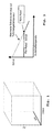
- Each function generator comprises a three-dimensional table (data cube), the functional area of which is defined by the flying machine number (MN), by the outside temperature in the form of the difference from the ISA temperature (DTAMB) and the altitude (ALT) in the form of a pressure associated therewith.
- the three-dimensional table indicates a target power based on the input Mach, altitude, and outside temperature signals, and each function generator, if the input signals fall between the values uniquely defined by the table (interpolation points) performs a triple interpolation to obtain the corresponding target power (target torque ).
- the data storage takes place in the data cube assigned to the corresponding engine power stage such that different altitude tables are created, which map the Mach number over the outside temperature.
- all height tables have exactly the same interpolation points (discrete values) between which interpolation is required if the input signals of the outside temperature, the Mach number and the altitude do not correspond to the interpolation points in order to determine intermediate values of the power.
- the thrust course is - provided that the maximum thrust on the basis of only a single power limiter, here the turbine gas temperature, in relation to the outside temperature at constant Mach number and altitude - determined by a minimum of three nodes, namely coldest day, the kink point and the hottest day, clearly defined.
- the number of support points can be kept low. Since exactly one kink point is defined for all engine heights for each engine power stage and a power limiter, the number of data points stored in a data cube moves in narrow limits that are manageable with regard to memory expenditure and storage capacity.
- the invention has for its object to provide a control system for achieving maximum engine performance on the basis of a plurality of power-limiting engine parameters, which requires a small storage capacity with reduced amount of data and time-constrained under the security aspect.
- three-dimensional data sets are created on the basis of the flight altitude, the outside temperature and the aircraft power and stored in the control system based on a plurality of power-limiting parameters for each of these power limiters.
- a comparator determines the lowest value on the basis of which the fuel supply to the engine is regulated.
- second three-dimensional data sets are stored which reduce the performance of the respective first data cube (three-dimensional data set) take into account the maximum performance due to air extraction for cabin and de-icing air. This means that only if air extraction actually leads to the exceeding of a maximum limiting and relevant to the flight condition limiter, the corresponding power is reduced. As long as no limiter is affected at the flight performance calculated by the control system, the full guaranteed power of the engine can still be provided when the air is removed.
- a constant maximum value of the power is stored in the control system for each engine power level, which maps the maximum guaranteed engine power per flight condition.
- the individual (first) data L11, L12, L13 and L14 compiled in the three abovementioned engine power levels for the various power-limiting parameters are each provided with a second (first) power output stage in the same engine power level and for the same power-limiting engine parameter (limiters L1 to L4) )
- Data cube L21, L22, L23 and L24 namely an air sampling data cube, immediately downstream, which takes into account in the control system a temperature and the speed increasing air extraction at the high pressure compressor for providing cabin air, by power reduction (bleed debit).
- the accessory data cube L21 to L24 in the embodiment according to FIG. 2 comprises the altitude (ALT), the outside temperature (DTAMB) and the air extraction related data.
- a maximum power limiter L5 is stored, which is constant regardless of the flight condition and represents a guaranteed maximum power. 2 also shows that with the present control system it is also possible to use the same first and second data cube, here by way of example L14 and L24, for two or more engine power levels for the power levels “cruise power" and "climb power". In the present embodiment, this relates to the maximum medium-pressure shaft speed (L4), which is the same for the relevant engine power levels. However, it could equally affect the limiting parameters of "high pressure speed” or “compressor pressure ratio” as well as other parameters. This further reduces both the required storage capacity and the effort required to create the data cube.
- a corresponding (maximum possible) power value LW1 to LW4 if necessary by the power extraction for air extraction corrected, read out.
- These power values LW1 to LW4, together with the power value LW5 set by the maximum power limiter L5, are input to a comparator V which selects the smallest (most critical) power value as the final power output of the control system to use this value to control the maximum possible power of the engine through the fuel control adjust.
Landscapes
- Engineering & Computer Science (AREA)
- Chemical & Material Sciences (AREA)
- Combustion & Propulsion (AREA)
- Mechanical Engineering (AREA)
- General Engineering & Computer Science (AREA)
- Feedback Control In General (AREA)
- Combined Controls Of Internal Combustion Engines (AREA)
- Control Of Eletrric Generators (AREA)
- Control Of Turbines (AREA)
Applications Claiming Priority (2)
| Application Number | Priority Date | Filing Date | Title |
|---|---|---|---|
| DE10329252 | 2003-06-25 | ||
| DE10329252A DE10329252A1 (de) | 2003-06-25 | 2003-06-25 | Regelsystem für ein Flugtriebwerk |
Publications (3)
| Publication Number | Publication Date |
|---|---|
| EP1491745A2 true EP1491745A2 (fr) | 2004-12-29 |
| EP1491745A3 EP1491745A3 (fr) | 2007-04-18 |
| EP1491745B1 EP1491745B1 (fr) | 2008-11-05 |
Family
ID=33395047
Family Applications (1)
| Application Number | Title | Priority Date | Filing Date |
|---|---|---|---|
| EP04090217A Expired - Lifetime EP1491745B1 (fr) | 2003-06-25 | 2004-06-04 | Système de contrôle électronique d'aéronef |
Country Status (3)
| Country | Link |
|---|---|
| US (1) | US7471996B2 (fr) |
| EP (1) | EP1491745B1 (fr) |
| DE (2) | DE10329252A1 (fr) |
Cited By (1)
| Publication number | Priority date | Publication date | Assignee | Title |
|---|---|---|---|---|
| US10683099B2 (en) | 2017-02-08 | 2020-06-16 | Pratt & Whitney Canada Corp. | Methods and systems for controlling operation of aircraft engines |
Families Citing this family (16)
| Publication number | Priority date | Publication date | Assignee | Title |
|---|---|---|---|---|
| DE10329252A1 (de) * | 2003-06-25 | 2005-01-13 | Rolls-Royce Deutschland Ltd & Co Kg | Regelsystem für ein Flugtriebwerk |
| FR2866109B1 (fr) * | 2004-02-05 | 2006-04-07 | Airbus France | Procede et dispositif de verification d'une valeur de temperature a une altitude de destination d'un aeronef. |
| FR2890939B1 (fr) * | 2005-09-22 | 2007-10-19 | Airbus Sas | Procede et dispositif pour fournir a un pilote d'un aeronef multimoteur des informations relatives auxdits moteurs |
| US8437941B2 (en) | 2009-05-08 | 2013-05-07 | Gas Turbine Efficiency Sweden Ab | Automated tuning of gas turbine combustion systems |
| US9354618B2 (en) | 2009-05-08 | 2016-05-31 | Gas Turbine Efficiency Sweden Ab | Automated tuning of multiple fuel gas turbine combustion systems |
| US9267443B2 (en) | 2009-05-08 | 2016-02-23 | Gas Turbine Efficiency Sweden Ab | Automated tuning of gas turbine combustion systems |
| US9671797B2 (en) | 2009-05-08 | 2017-06-06 | Gas Turbine Efficiency Sweden Ab | Optimization of gas turbine combustion systems low load performance on simple cycle and heat recovery steam generator applications |
| FR2992354B1 (fr) * | 2012-06-20 | 2015-09-18 | Snecma | Procede et dispositif d'ajustement d'une valeur de consigne d'un parametre influencant une poussee d'un moteur a turbine a gaz |
| EP2904251B1 (fr) * | 2012-10-01 | 2019-06-26 | United Technologies Corporation | Procédé de définition de calibres de réglage d'un moteur à turbines à gaz |
| US20140182297A1 (en) * | 2013-01-03 | 2014-07-03 | General Electric Company | Gas turbine and method of controlling a gas turbine at part-load condition |
| US10351255B2 (en) * | 2016-01-18 | 2019-07-16 | Pratt & Whitney Canada Corp. | Digital communications between aircraft computer and engine computer |
| EP3282110B1 (fr) * | 2016-08-08 | 2019-10-16 | Rolls-Royce PLC | Procédé de fonctionnement d'un moteur et d'un générateur |
| US11214380B2 (en) | 2017-05-31 | 2022-01-04 | General Electric Company | Intelligent mission thermal management system |
| US11391218B2 (en) | 2019-03-22 | 2022-07-19 | Pratt & Whitney Canada Corp. | Method and system for setting power of an aircraft engine |
| US12399507B2 (en) * | 2021-11-15 | 2025-08-26 | Beta Air Llc | Systems and methods for controlling a flight boundary of an aircraft |
| CN117131610A (zh) * | 2023-10-25 | 2023-11-28 | 北京蓝天航空科技股份有限公司 | 发动机推力的计算方法、装置、电子设备及介质 |
Family Cites Families (28)
| Publication number | Priority date | Publication date | Assignee | Title |
|---|---|---|---|---|
| DE68928159T2 (de) * | 1988-09-20 | 1997-10-30 | United Technologies Corp | Steuervorrichtung für Gasturbinenanlagen |
| EP0427952A1 (fr) * | 1989-11-16 | 1991-05-22 | Westinghouse Electric Corporation | Appareil et méthode pour limiter un excès de carburant dans une turbine à combustion avec générateur |
| US5175710A (en) * | 1990-12-14 | 1992-12-29 | Hutson William H | Multi-dimensional data processing and display |
| US5315819A (en) * | 1991-09-17 | 1994-05-31 | Allied-Signal Inc. | Power management system for turbine engines |
| US5285634A (en) * | 1991-12-09 | 1994-02-15 | United Technologies Corporation | Aircraft gas turbine engine control |
| US5586026A (en) * | 1991-12-20 | 1996-12-17 | Schlumberger Technology Corporation | Method of seismic migration using a massively parallel computer |
| US5349527A (en) * | 1991-12-20 | 1994-09-20 | Schlumberger Technology Corporation | Method of seismic time migration using a massively parallel computer |
| US5832475A (en) * | 1996-03-29 | 1998-11-03 | International Business Machines Corporation | Database system and method employing data cube operator for group-by operations |
| US5732546A (en) * | 1996-07-19 | 1998-03-31 | General Electric Company | Transient turbine overtemperature control |
| US5694760A (en) * | 1996-07-19 | 1997-12-09 | General Electric Company | Cumbustor lean flameout control |
| US5926820A (en) * | 1997-02-27 | 1999-07-20 | International Business Machines Corporation | Method and system for performing range max/min queries on a data cube |
| US5978788A (en) * | 1997-04-14 | 1999-11-02 | International Business Machines Corporation | System and method for generating multi-representations of a data cube |
| US5890151A (en) * | 1997-05-09 | 1999-03-30 | International Business Machines Corporation | Method and system for performing partial-sum queries on a data cube |
| US6853452B1 (en) * | 1999-03-17 | 2005-02-08 | University Of Virginia Patent Foundation | Passive remote sensor of chemicals |
| US6209821B1 (en) * | 1999-09-14 | 2001-04-03 | The United States Of America As Represented By The Administrator Of The National Aeronautics And Space Administration | Apparatus and method for measuring air temperature ahead of an aircraft for controlling a variable inlet/engine assembly |
| US6341247B1 (en) * | 1999-12-17 | 2002-01-22 | Mcdonell Douglas Corporation | Adaptive method to control and optimize aircraft performance |
| US6389816B1 (en) * | 2000-07-25 | 2002-05-21 | Honeywell International, Inc. | Simplified fuel system for jet engines |
| US6633828B2 (en) * | 2001-03-21 | 2003-10-14 | Honeywell International Inc. | Speed signal variance detection fault system and method |
| EP1423804A4 (fr) * | 2001-08-10 | 2006-11-08 | Datavine Res Services | Procede et appareil permettant l'acces, l'integration, et l'analyse de sources de donnees heterogenes par la manipulation d'objets de metadonnees |
| US6748744B2 (en) * | 2001-11-21 | 2004-06-15 | Pratt & Whitney Canada Corp. | Method and apparatus for the engine control of output shaft speed |
| WO2003078813A1 (fr) * | 2002-03-20 | 2003-09-25 | Ebara Corporation | Dispositif a turbine a gaz |
| US6778884B2 (en) * | 2002-06-11 | 2004-08-17 | Honeywell International, Inc. | System and method for generating consolidated gas turbine control tables |
| GB2397395B (en) * | 2003-01-16 | 2006-04-05 | Rolls Royce Plc | Controlling the fuel supply to a combustor of a gas turbine engine |
| US7058640B2 (en) * | 2003-02-05 | 2006-06-06 | International Business Machines Corporation | Systems, methods, and computer program products to efficiently update multidimensional databases |
| DE10329252A1 (de) * | 2003-06-25 | 2005-01-13 | Rolls-Royce Deutschland Ltd & Co Kg | Regelsystem für ein Flugtriebwerk |
| US7194392B2 (en) * | 2003-10-23 | 2007-03-20 | Taner Tuken | System for estimating model parameters |
| TWI264686B (en) * | 2004-12-30 | 2006-10-21 | Ind Tech Res Inst | Method and system with multiple purpose and functions for alarm performance assessment |
| US7120535B2 (en) * | 2005-01-14 | 2006-10-10 | Delphi Technologies, Inc. | Method and apparatus to evaluate an intake air temperature monitoring circuit |
-
2003
- 2003-06-25 DE DE10329252A patent/DE10329252A1/de not_active Withdrawn
-
2004
- 2004-06-04 DE DE502004008383T patent/DE502004008383D1/de not_active Expired - Lifetime
- 2004-06-04 EP EP04090217A patent/EP1491745B1/fr not_active Expired - Lifetime
- 2004-06-25 US US10/875,684 patent/US7471996B2/en not_active Expired - Fee Related
Cited By (1)
| Publication number | Priority date | Publication date | Assignee | Title |
|---|---|---|---|---|
| US10683099B2 (en) | 2017-02-08 | 2020-06-16 | Pratt & Whitney Canada Corp. | Methods and systems for controlling operation of aircraft engines |
Also Published As
| Publication number | Publication date |
|---|---|
| US7471996B2 (en) | 2008-12-30 |
| EP1491745B1 (fr) | 2008-11-05 |
| EP1491745A3 (fr) | 2007-04-18 |
| DE10329252A1 (de) | 2005-01-13 |
| DE502004008383D1 (de) | 2008-12-18 |
| US20040267414A1 (en) | 2004-12-30 |
Similar Documents
| Publication | Publication Date | Title |
|---|---|---|
| EP1491745B1 (fr) | Système de contrôle électronique d'aéronef | |
| DE3871971T2 (de) | Uebergangsregelsystem fuer einen gasturbinenmotor. | |
| DE68906898T2 (de) | Kraftstoffsteuerungssystem. | |
| DE69923441T2 (de) | Einhebelleistungsregler für bemannte und unbemannte flugzeuge | |
| DE2432930A1 (de) | Selbstkorrigierende, rueckgekoppelte steuerung | |
| DE2516900A1 (de) | Steuersystem fuer triebwerkanlagen | |
| EP1215383A1 (fr) | Procédé de réglage d'une turbine à gaz pour aéronef | |
| DE3028574A1 (de) | Schubsteuerungssystem fuer ein gasturbinen-strahltriebwerk | |
| DE2909825A1 (de) | Steuersystem fuer einen mehrstufigen axialstroemungskompressor eines gasturbinentriebwerks | |
| DE3023550A1 (de) | Steuersystem zur steuerung der kraftstoffzufuhr bei einer gasturbine | |
| EP0089482B1 (fr) | Procédé pour la commande électronique de l'àdmission de carburant dans un moteur à combustion à auto-allumage | |
| DE3436338C2 (fr) | ||
| EP1970542B1 (fr) | Décalage d'aube en fonction d'étranglement dans des turbomachines | |
| DE2214338A1 (de) | Drehmoment-Regelsystem für eine Gasturbine | |
| DE69007922T2 (de) | Dynamische Kompensation des Beschleunigungsprogrammes. | |
| EP1043483B1 (fr) | Méthode de régulation de la lubrification en particulier pour un moteur à combustion interne et dispositif selon cette méthode | |
| DE69100985T2 (de) | Brennstoffversorgungssystem für einen Turbomotor. | |
| DE3429672A1 (de) | Drehzahlregelsystem fuer brennkraftmaschinen | |
| DE2827581A1 (de) | Mit einer hilfssteuereinrichtung versehene steuereinrichtung fuer ein gasturbinentriebwerk | |
| DE2850625A1 (de) | Vorrichtung und verfahren zur temperaturanzeige | |
| EP1802859A1 (fr) | Procede pour faire fonctionner un systeme d'injection de carburant en particulier d'un vehicule automobile | |
| DE3541148C2 (fr) | ||
| WO2009092409A1 (fr) | Procédé pour régler une turbomachine | |
| DE102014211394A1 (de) | Geschwindigkeitskontrolleinrichtung für einen hydrostatischen Antrieb | |
| EP0358139A2 (fr) | Système et méthode de régulation |
Legal Events
| Date | Code | Title | Description |
|---|---|---|---|
| PUAI | Public reference made under article 153(3) epc to a published international application that has entered the european phase |
Free format text: ORIGINAL CODE: 0009012 |
|
| AK | Designated contracting states |
Kind code of ref document: A2 Designated state(s): AT BE BG CH CY CZ DE DK EE ES FI FR GB GR HU IE IT LI LU MC NL PL PT RO SE SI SK TR |
|
| AX | Request for extension of the european patent |
Extension state: AL HR LT LV MK |
|
| RIN1 | Information on inventor provided before grant (corrected) |
Inventor name: BARTEL, MATTHIAS |
|
| PUAL | Search report despatched |
Free format text: ORIGINAL CODE: 0009013 |
|
| AK | Designated contracting states |
Kind code of ref document: A3 Designated state(s): AT BE BG CH CY CZ DE DK EE ES FI FR GB GR HU IE IT LI LU MC NL PL PT RO SE SI SK TR |
|
| AX | Request for extension of the european patent |
Extension state: AL HR LT LV MK |
|
| 17P | Request for examination filed |
Effective date: 20070525 |
|
| AKX | Designation fees paid |
Designated state(s): DE FR GB |
|
| GRAP | Despatch of communication of intention to grant a patent |
Free format text: ORIGINAL CODE: EPIDOSNIGR1 |
|
| RTI1 | Title (correction) |
Free format text: ELECTRONIC AIRCRAFT ENGINE CONTROL SYSTEM |
|
| GRAS | Grant fee paid |
Free format text: ORIGINAL CODE: EPIDOSNIGR3 |
|
| GRAA | (expected) grant |
Free format text: ORIGINAL CODE: 0009210 |
|
| AK | Designated contracting states |
Kind code of ref document: B1 Designated state(s): DE FR GB |
|
| REG | Reference to a national code |
Ref country code: GB Ref legal event code: FG4D Free format text: NOT ENGLISH |
|
| REF | Corresponds to: |
Ref document number: 502004008383 Country of ref document: DE Date of ref document: 20081218 Kind code of ref document: P |
|
| PLBE | No opposition filed within time limit |
Free format text: ORIGINAL CODE: 0009261 |
|
| STAA | Information on the status of an ep patent application or granted ep patent |
Free format text: STATUS: NO OPPOSITION FILED WITHIN TIME LIMIT |
|
| 26N | No opposition filed |
Effective date: 20090806 |
|
| REG | Reference to a national code |
Ref country code: DE Ref legal event code: R082 Ref document number: 502004008383 Country of ref document: DE |
|
| REG | Reference to a national code |
Ref country code: FR Ref legal event code: PLFP Year of fee payment: 13 |
|
| REG | Reference to a national code |
Ref country code: FR Ref legal event code: PLFP Year of fee payment: 14 |
|
| REG | Reference to a national code |
Ref country code: FR Ref legal event code: PLFP Year of fee payment: 15 |
|
| PGFP | Annual fee paid to national office [announced via postgrant information from national office to epo] |
Ref country code: FR Payment date: 20190625 Year of fee payment: 16 |
|
| PGFP | Annual fee paid to national office [announced via postgrant information from national office to epo] |
Ref country code: GB Payment date: 20190627 Year of fee payment: 16 Ref country code: DE Payment date: 20190627 Year of fee payment: 16 |
|
| REG | Reference to a national code |
Ref country code: DE Ref legal event code: R119 Ref document number: 502004008383 Country of ref document: DE |
|
| GBPC | Gb: european patent ceased through non-payment of renewal fee |
Effective date: 20200604 |
|
| PG25 | Lapsed in a contracting state [announced via postgrant information from national office to epo] |
Ref country code: FR Free format text: LAPSE BECAUSE OF NON-PAYMENT OF DUE FEES Effective date: 20200630 Ref country code: GB Free format text: LAPSE BECAUSE OF NON-PAYMENT OF DUE FEES Effective date: 20200604 |
|
| PG25 | Lapsed in a contracting state [announced via postgrant information from national office to epo] |
Ref country code: DE Free format text: LAPSE BECAUSE OF NON-PAYMENT OF DUE FEES Effective date: 20210101 |