EP1491760A1 - Soupape d'injection de carburant - Google Patents
Soupape d'injection de carburant Download PDFInfo
- Publication number
- EP1491760A1 EP1491760A1 EP04009262A EP04009262A EP1491760A1 EP 1491760 A1 EP1491760 A1 EP 1491760A1 EP 04009262 A EP04009262 A EP 04009262A EP 04009262 A EP04009262 A EP 04009262A EP 1491760 A1 EP1491760 A1 EP 1491760A1
- Authority
- EP
- European Patent Office
- Prior art keywords
- fuel
- injection valve
- fuel injection
- valve according
- actuator
- Prior art date
- Legal status (The legal status is an assumption and is not a legal conclusion. Google has not performed a legal analysis and makes no representation as to the accuracy of the status listed.)
- Granted
Links
- 239000000446 fuel Substances 0.000 title claims abstract description 81
- 238000002347 injection Methods 0.000 claims description 27
- 239000007924 injection Substances 0.000 claims description 27
- 239000012528 membrane Substances 0.000 claims description 8
- 238000002485 combustion reaction Methods 0.000 claims description 7
- 229910000831 Steel Inorganic materials 0.000 claims description 6
- 239000010959 steel Substances 0.000 claims description 6
- 238000007789 sealing Methods 0.000 claims description 4
- 238000011144 upstream manufacturing Methods 0.000 abstract description 2
- 238000011161 development Methods 0.000 description 5
- 230000018109 developmental process Effects 0.000 description 5
- 238000004519 manufacturing process Methods 0.000 description 4
- 239000007921 spray Substances 0.000 description 3
- 238000006243 chemical reaction Methods 0.000 description 2
- 238000012790 confirmation Methods 0.000 description 2
- 230000000694 effects Effects 0.000 description 2
- 238000000034 method Methods 0.000 description 2
- 238000003466 welding Methods 0.000 description 2
- 238000005452 bending Methods 0.000 description 1
- 238000010276 construction Methods 0.000 description 1
- 238000009434 installation Methods 0.000 description 1
- 238000005304 joining Methods 0.000 description 1
- 230000001050 lubricating effect Effects 0.000 description 1
- 239000007787 solid Substances 0.000 description 1
- 238000005507 spraying Methods 0.000 description 1
Images

Classifications
-
- F—MECHANICAL ENGINEERING; LIGHTING; HEATING; WEAPONS; BLASTING
- F02—COMBUSTION ENGINES; HOT-GAS OR COMBUSTION-PRODUCT ENGINE PLANTS
- F02M—SUPPLYING COMBUSTION ENGINES IN GENERAL WITH COMBUSTIBLE MIXTURES OR CONSTITUENTS THEREOF
- F02M51/00—Fuel-injection apparatus characterised by being operated electrically
- F02M51/06—Injectors peculiar thereto with means directly operating the valve needle
- F02M51/0603—Injectors peculiar thereto with means directly operating the valve needle using piezoelectric or magnetostrictive operating means
-
- F—MECHANICAL ENGINEERING; LIGHTING; HEATING; WEAPONS; BLASTING
- F02—COMBUSTION ENGINES; HOT-GAS OR COMBUSTION-PRODUCT ENGINE PLANTS
- F02M—SUPPLYING COMBUSTION ENGINES IN GENERAL WITH COMBUSTIBLE MIXTURES OR CONSTITUENTS THEREOF
- F02M61/00—Fuel-injectors not provided for in groups F02M39/00 - F02M57/00 or F02M67/00
- F02M61/04—Fuel-injectors not provided for in groups F02M39/00 - F02M57/00 or F02M67/00 having valves, e.g. having a plurality of valves in series
- F02M61/08—Fuel-injectors not provided for in groups F02M39/00 - F02M57/00 or F02M67/00 having valves, e.g. having a plurality of valves in series the valves opening in direction of fuel flow
Definitions
- the invention relates to a fuel injector according to the preamble of the main claim.
- a fuel injection valve with an actuation line with an actuator, a valve needle, a hydraulic conversion device and a return spring that actuate a valve closing body is known.
- the conversion device is used to convert a small actuator stroke to a larger valve needle stroke and to compensate for different, temperature-related changes in length of components.
- the corrugated tubular design of the flexible sections is intended to prevent the flexible sections subjected to fuel pressure on one side from exerting axial forces on the actuating strand.
- a disadvantage of this known prior art is that the flexible sections acting as a seal are very have to be elaborately manufactured in order to achieve a satisfactory fatigue strength. In order to withstand the radially acting forces of the fuel pressure, however, they must also have a corresponding radial rigidity. This radial stiffness further increases the manufacturing effort and the manufacturing costs and has a disadvantageous effect on the valve dynamics due to the accompanying axial stiffness. The space of such seals and the surface area exposed to the fuel pressure is increased.
- the fuel injector according to the invention with the characterizing features of the main claim has the advantage that it is possible to dispense with disadvantageously large, error-prone flexible sections or seals which have a negative effect on the valve dynamics and are expensive to produce.
- the manufacturing cost of the fuel injector is significantly reduced, the size can be reduced without functional losses and the reliability of the fuel injector is increased.
- the forces of the fuel pressure acting in opposite axial directions can advantageously be used to support or take over functional processes in the fuel injector.
- a spring element that only prestresses the actuator which, for example, runs around the actuator as a tubular spring, can be dimensioned with a lower pretensioning force or can be omitted entirely.
- the actuator module can thus be assembled and assembled more easily.
- the actuation train has a hydraulic coupler to compensate for temperature-related changes in length of the actuator and / or other components and / or to convert the stroke, the coupler being arranged on the inflow side of the actuator in a further development.
- the fuel injector can be designed in a particularly reliable and simple manner.
- the coupler cylinder can be arranged in a particularly simple manner, for example in the valve housing.
- the hydraulic coupler has an equalization space, a leakage gap and a membrane space, the leakage gap connecting the equalization space with the membrane space, the hydraulic coupler is constructed in a particularly simple manner.
- the hydraulic coupler is advantageously completely filled with a hydraulic medium and a third flexible section separates or seals the hydraulic medium from fuel.
- the coupler can in particular be made more durable and reliable, since the properties of the hydraulic medium can be chosen largely independently of the choice of fuel. In this way, for example, the viscosity and the lubricating properties of the hydraulic medium can be freely selected.
- the third flexible section is advantageously designed in such a way that it largely transmits the fuel pressure applied to it on one side to the hydraulic medium.
- the fuel pressure can thus be used in a particularly simple and advantageous manner to keep the compensation space filled with hydraulic medium.
- the flexible sections have a perforated plate shape and are essentially U-shaped in cross section. The flexibility will thereby increased, the flexible sections can be joined more easily and are easy to manufacture.
- the fuel injector can be manufactured in a particularly compact manner.
- the individual flexible sections are advantageously connected to the actuating strand via flanges.
- the flexible sections can be connected to the actuating strand in a particularly simple manner. In particular, this increases the safety and durability of the joint between the flexible sections and the actuating strand, as well as the ease of installation of the flexible sections.
- the first flexible section and the second flexible section are advantageously arranged in such a way that the fuel pressure acting directly and indirectly on the valve closing body is canceled out by force in the axial direction of the actuation line.
- the spring force of a biasing spring acting on the actuating strand can be selected to be significantly smaller. Due to the reduced spring force of the biasing spring acting counter to the confirmation direction of the actuator, a smaller and less expensive actuator can be used. The power requirement of the actuator is reduced and the heat development in the actuator and in the control unit is reduced.
- the coupler Due to the reduced spring force acting on the coupler, the coupler can very quickly compensate for temperature-related linear expansions in cold start phases, in which the valve opening times are usually extended, which also enables cold start phases with reduced fuel pressure.
- the fuel injection valve 1 according to the invention shown schematically in FIG. 1 is particularly suitable as a fuel injection valve 1 for fuel injection systems for mixture-compressing, spark-ignited internal combustion engines for the direct injection of fuel into the combustion chamber of the internal combustion engine.
- the fuel injection valve 1 comprises in particular a piezoelectric, magnetostrictive or electrostrictive actuator 2, which is arranged in an actuator module 22.
- the actuator 2 or the actuator module 22 is part of a confirmation line, which in this exemplary embodiment also has a hydraulic coupler 3 arranged on the inflow side of the actuator module 22 and a valve needle 4 arranged on the outflow side of the actuator module 22.
- the actuator module 22, the hydraulic coupler 3 and the valve needle 4 are arranged coaxially in a valve housing 6.
- the valve housing 6 has at its downstream end a nozzle body 5 through which the valve needle 4 coaxially grips and at its downstream end a valve seat body 10 formed integrally with the nozzle body 5 and having a spray opening 7 is arranged.
- a valve seat surface 9 formed on the valve seat body 10 interacts with a valve closing body 8 formed on the spray-side end of the valve needle 4 to form a sealing seat.
- the fuel injection valve 1 opens to the outside.
- the valve housing 6 On the inflow side, the valve housing 6 has an upper valve part 33.
- the upper valve part 33 lies hermetically sealed on the inflow end of the valve housing 6 with a first shoulder 34, is integrally joined to the valve housing 6 there, for example, and engages with the outflow end of the valve housing 6.
- the leakage gap 24 connects a compensating chamber 31 formed at the top between the coupler cylinder 23 and the compensating piston 21 and a diaphragm chamber 32 oriented at the bottom towards the actuator module 22.
- the diaphragm chamber 32 is closed or sealed on the downstream side by a third flexible section 28.
- the membrane-like and perforated plate-shaped third flexible section 28 is hermetically sealed in the region of the outer circumference with the downstream end of the valve upper part 33 engaging in the actuator housing 6 below a diameter-reducing second shoulder 35, for example by welding or other material-fitting joining methods.
- the third flexible section 28 is hermetically sealed and integrally joined to the compensating piston 21, which tapers towards the actuator module 22 and penetrates the third flexible section 28.
- the third flexible section 28 which is made of steel or a steel government, has a U-shaped or undulating profile in cross section. The third flexible section 28 is thereby not subjected to tension, but advantageously to bending.
- the coupler cylinder 23, the compensating piston 21, the compensating chamber 31, the leakage gap 24 and the membrane chamber 32 form the hydraulic coupler 3 in this exemplary embodiment.
- the hydraulic coupler 3, or the compensating chamber 31, the leakage gap 24 and the membrane chamber 32 are completely one Hydraulic medium 30 filled.
- the hydraulic medium 30 is a highly heat-conducting and highly viscous oil.
- the electrical connection 15 extends further in the valve housing 6 in order to enter the actuator module 22 at the same level.
- a perforated plate-shaped, essentially U-shaped cross-section and made of steel is made of steel and its outer circumference is integrally and hermetically sealed with its outer circumference.
- the latter is cohesively and hermetically sealed on the upper side of a third flange 29, which surrounds the end of the compensating piston 21 tapering in diameter.
- the downstream flange of the third flange 29 engages in a conical recess 27 arranged in the top of the actuator module 22 in an actuator foot 13, with which it is ideally in constant contact.
- An annular groove 36 belonging to the first fuel channel 17 is arranged directly below the second shoulder 35 and above the outer circumference of the third flexible section 28.
- the fuel injector 1 is in operation the space between the first flexible section 25 and the third flexible section 28 is completely filled with fuel via the first fuel channel 17.
- the fuel presses on one side of each of the first flexible section 25 and third flexible section 28.
- Fuel pressure in this way acts on the hydraulic medium 30 that is softer, in particular thinner, than the first flexible section 25 on the hydraulic medium 30
- Fuel pressure prevailing in the third flexible section 28 and the first flexible section 25 also acts on the first flexible section 25 such that the actuator module 22 is loaded from above via the third flange 29 on the actuator foot 13 with a prestress acting in the spraying direction.
- valve needle 4 is biased against the spray direction by a biasing spring 11 which engages the valve needle 4 via a second flange 20.
- the valve closing body 8 is thereby pulled into the sealing seat and the conically shaped, upstream end of the valve needle 4 is pressed into a second recess 37 arranged in an actuator head 12.
- a first flange 19 is integrally connected to the valve needle 4, for example by welding.
- a second flexible section 26 is integrally and hermetically sealed to the underside of the first flange 19. In the area of the outer circumference of the second flexible section 26, the latter is connected to the nozzle body 5 in a cohesive and hermetically sealed manner.
- the second flexible section 26 can also be joined to the valve housing 6 in the region of its outer circumference. Coming under pressure in the second fuel channel 18 in the valve housing 6 from the actuator module 22 and the biasing spring 11, the fuel, coming from below, is flushed around the biasing spring 11 and the second flange 20 to the second flexible section 26. The one-sided on the second Flexible section 26 acting fuel pressure presses the valve needle 4 in the axial direction towards the actuator module 22 against the spray direction via the first flange 19.
- a spring element 14 belonging to the actuator module 22 tensions the actuator foot 13 against the actuator head 12, so that the actuator 2 is under prestress.
- the actuator 2 If the actuator 2 is excited via the electrical connection 15, it expands in the axial direction and acts on the compensating piston 21 via the actuator foot 13. Due to the speed of the movement of the actuator 2 and the relatively narrow leakage gap 24, the hydraulic medium 30 behaves similarly to a solid body. The changes in length of the actuator 2 can thereby be almost completely transferred to the valve needle 4, whereby the valve closing body 8 lifts off the valve seat surface 9 and fuel is injected into the combustion chamber, not shown, of the internal combustion engine, not shown. When the actuator 2 moves slowly, for example as a result of thermal influences, the hydraulic medium 30 is displaced into the membrane space 32 through the leakage gap 24, as a result of which an arbitrary opening of the fuel injection valve 1 is prevented.
- the first flexible section 25 and the second flexible section 26 are dimensioned and arranged such that the forces of the fuel pressure acting axially, centrally and directly on the valve closing body 8 essentially cancel each other out.
- the fuel injection valve 1 can thereby be operated at different fuel pressures without, for example, the spring force of the biasing spring 11 having to be designed adaptively by means of complex measures.
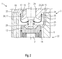
- FIG. 2 shows a schematic illustration of a second exemplary embodiment of a fuel injection valve 1 according to the invention in the region of the actuator head 12, similar to the first exemplary embodiment from FIG. 1
- the third flexible section 28 used in the first exemplary embodiment There is no difference in the third flexible section 28 used in the first exemplary embodiment.
- the fuel guided through the first fuel channel 17 and the annular groove 36 fills the hydraulic coupler 3 in this exemplary embodiment, with the result that the hydraulic medium 30 consists of fuel.
- the structure of the fuel injector 1 is simplified.
- the invention is not limited to the exemplary embodiments shown and is also suitable for any other construction of fuel injection valves 1, in particular fuel injection valves opening inwards.
Landscapes
- Engineering & Computer Science (AREA)
- Chemical & Material Sciences (AREA)
- Combustion & Propulsion (AREA)
- Mechanical Engineering (AREA)
- General Engineering & Computer Science (AREA)
- Fuel-Injection Apparatus (AREA)
Applications Claiming Priority (2)
| Application Number | Priority Date | Filing Date | Title |
|---|---|---|---|
| DE10328573A DE10328573A1 (de) | 2003-06-25 | 2003-06-25 | Brennstoffeinspritzventil |
| DE10328573 | 2003-06-25 |
Publications (2)
| Publication Number | Publication Date |
|---|---|
| EP1491760A1 true EP1491760A1 (fr) | 2004-12-29 |
| EP1491760B1 EP1491760B1 (fr) | 2006-09-27 |
Family
ID=33394978
Family Applications (1)
| Application Number | Title | Priority Date | Filing Date |
|---|---|---|---|
| EP20040009262 Expired - Lifetime EP1491760B1 (fr) | 2003-06-25 | 2004-04-20 | Soupape d'injection de carburant |
Country Status (2)
| Country | Link |
|---|---|
| EP (1) | EP1491760B1 (fr) |
| DE (2) | DE10328573A1 (fr) |
Families Citing this family (1)
| Publication number | Priority date | Publication date | Assignee | Title |
|---|---|---|---|---|
| DE102008041544B4 (de) * | 2008-08-26 | 2016-05-12 | Robert Bosch Gmbh | Ventil zur Zumessung eines flüssigen oder gasförmigen Mediums |
Citations (14)
| Publication number | Priority date | Publication date | Assignee | Title |
|---|---|---|---|---|
| US4725002A (en) * | 1985-09-17 | 1988-02-16 | Robert Bosch Gmbh | Measuring valve for dosing liquids or gases |
| US5896845A (en) * | 1996-04-19 | 1999-04-27 | Futaba Denshi Kogyo K.K. | Engine for models and method for controlling engine for models |
| EP1079099A2 (fr) * | 1999-08-24 | 2001-02-28 | Siemens Aktiengesellschaft | Soupape de dosage |
| EP1111230A2 (fr) * | 1999-12-22 | 2001-06-27 | Siemens Aktiengesellschaft | Dispositif hydraulique pour transmettre le mouvement d'un actuateur |
| DE10039543A1 (de) * | 2000-08-12 | 2002-02-28 | Daimler Chrysler Ag | Einspritzventil |
| DE10141136A1 (de) * | 2001-04-07 | 2002-10-10 | Continental Teves Ag & Co Ohg | Ventil.insbesondere für hydraulische Kraftfahrzeugbremsen |
| US6467460B1 (en) * | 1999-03-20 | 2002-10-22 | Robert Bosch Gmbh | Fuel injection valve |
| US20020153429A1 (en) * | 2000-01-28 | 2002-10-24 | Friedrich Boecking | Injection nozzle |
| US6478013B1 (en) * | 1999-01-18 | 2002-11-12 | Robert Bosch Gmbh | Fuel injection valve and method for operating a fuel injection valve |
| DE10129375A1 (de) * | 2001-06-20 | 2003-01-02 | Mtu Friedrichshafen Gmbh | Injektor mit Piezo-Aktuator |
| DE10159749A1 (de) * | 2001-12-05 | 2003-06-12 | Bosch Gmbh Robert | Brennstoffeinspritzventil |
| WO2003048559A1 (fr) * | 2001-11-30 | 2003-06-12 | Robert Bosch Gmbh | Soupape d'injection de carburant |
| US6626373B1 (en) * | 1999-09-30 | 2003-09-30 | Robert Bosch Gmbh | Fuel injection valve |
| US6712289B1 (en) * | 1999-11-12 | 2004-03-30 | Robert Bosch Gmbh | Fuel injection valve |
Family Cites Families (2)
| Publication number | Priority date | Publication date | Assignee | Title |
|---|---|---|---|---|
| DE19928916B4 (de) * | 1999-06-24 | 2017-12-14 | Robert Bosch Gmbh | Brennstoffeinspritzventil |
| DE10007733A1 (de) * | 2000-02-19 | 2001-08-23 | Daimler Chrysler Ag | Einspritzventil |
-
2003
- 2003-06-25 DE DE10328573A patent/DE10328573A1/de not_active Withdrawn
-
2004
- 2004-04-20 DE DE200450001567 patent/DE502004001567D1/de not_active Expired - Lifetime
- 2004-04-20 EP EP20040009262 patent/EP1491760B1/fr not_active Expired - Lifetime
Patent Citations (14)
| Publication number | Priority date | Publication date | Assignee | Title |
|---|---|---|---|---|
| US4725002A (en) * | 1985-09-17 | 1988-02-16 | Robert Bosch Gmbh | Measuring valve for dosing liquids or gases |
| US5896845A (en) * | 1996-04-19 | 1999-04-27 | Futaba Denshi Kogyo K.K. | Engine for models and method for controlling engine for models |
| US6478013B1 (en) * | 1999-01-18 | 2002-11-12 | Robert Bosch Gmbh | Fuel injection valve and method for operating a fuel injection valve |
| US6467460B1 (en) * | 1999-03-20 | 2002-10-22 | Robert Bosch Gmbh | Fuel injection valve |
| EP1079099A2 (fr) * | 1999-08-24 | 2001-02-28 | Siemens Aktiengesellschaft | Soupape de dosage |
| US6626373B1 (en) * | 1999-09-30 | 2003-09-30 | Robert Bosch Gmbh | Fuel injection valve |
| US6712289B1 (en) * | 1999-11-12 | 2004-03-30 | Robert Bosch Gmbh | Fuel injection valve |
| EP1111230A2 (fr) * | 1999-12-22 | 2001-06-27 | Siemens Aktiengesellschaft | Dispositif hydraulique pour transmettre le mouvement d'un actuateur |
| US20020153429A1 (en) * | 2000-01-28 | 2002-10-24 | Friedrich Boecking | Injection nozzle |
| DE10039543A1 (de) * | 2000-08-12 | 2002-02-28 | Daimler Chrysler Ag | Einspritzventil |
| DE10141136A1 (de) * | 2001-04-07 | 2002-10-10 | Continental Teves Ag & Co Ohg | Ventil.insbesondere für hydraulische Kraftfahrzeugbremsen |
| DE10129375A1 (de) * | 2001-06-20 | 2003-01-02 | Mtu Friedrichshafen Gmbh | Injektor mit Piezo-Aktuator |
| WO2003048559A1 (fr) * | 2001-11-30 | 2003-06-12 | Robert Bosch Gmbh | Soupape d'injection de carburant |
| DE10159749A1 (de) * | 2001-12-05 | 2003-06-12 | Bosch Gmbh Robert | Brennstoffeinspritzventil |
Also Published As
| Publication number | Publication date |
|---|---|
| DE10328573A1 (de) | 2005-01-13 |
| DE502004001567D1 (de) | 2006-11-09 |
| EP1491760B1 (fr) | 2006-09-27 |
Similar Documents
| Publication | Publication Date | Title |
|---|---|---|
| EP1115970B1 (fr) | Soupape d'injection de carburant | |
| DE102007028490A1 (de) | Koppler zur Hubübertragung mittels Scherkraft, Injektor, sowie Verfahren zur Hubübertragung | |
| EP1421271B1 (fr) | Soupape d'injection de carburant | |
| DE10039424A1 (de) | Dosierventil mit einem hydraulischen Übertragungselement | |
| EP1456526B1 (fr) | Soupape d'injection de carburant | |
| EP1378657B1 (fr) | Injecteur de carburant | |
| DE10217594A1 (de) | Brennstoffeinspritzventil | |
| DE10149914A1 (de) | Brennstoffeinspritzventil | |
| EP1454056B1 (fr) | Soupape d'injection de carburant | |
| EP1431568B1 (fr) | Soupape d'injection de carburant | |
| EP1144848B1 (fr) | Soupape d'injection de carburant | |
| EP1519036B1 (fr) | Injecteur de carburant | |
| DE10213858A1 (de) | Brennstoffeinspritzventil | |
| EP1538331B1 (fr) | Soupape d'injection de carburant | |
| EP1491760B1 (fr) | Soupape d'injection de carburant | |
| EP1714026B1 (fr) | Soupape d'injection de carburant | |
| DE10353641B4 (de) | Brennstoffeinspritzventil | |
| EP2899393A1 (fr) | Vanne pour l'ajout de fluide | |
| EP1519035A1 (fr) | Soupape d'injection de combustible | |
| DE102016007121A1 (de) | Injektor für Reduktionsmittel | |
| EP1519034B1 (fr) | Soupape d'injection de carburant | |
| EP2317117B1 (fr) | Module d'actionneur et soupape d'injection de carburant | |
| DE102006017927A1 (de) | Brennstoffeinspritzventil | |
| EP1406006B1 (fr) | Soupape d'injection de carburant | |
| DE10152253B4 (de) | Ventil zum Steuern von Flüssigkeiten |
Legal Events
| Date | Code | Title | Description |
|---|---|---|---|
| PUAI | Public reference made under article 153(3) epc to a published international application that has entered the european phase |
Free format text: ORIGINAL CODE: 0009012 |
|
| AK | Designated contracting states |
Kind code of ref document: A1 Designated state(s): AT BE BG CH CY CZ DE DK EE ES FI FR GB GR HU IE IT LI LU MC NL PL PT RO SE SI SK TR |
|
| AX | Request for extension of the european patent |
Extension state: AL HR LT LV MK |
|
| 17P | Request for examination filed |
Effective date: 20050629 |
|
| AKX | Designation fees paid |
Designated state(s): DE FR GB IT |
|
| GRAP | Despatch of communication of intention to grant a patent |
Free format text: ORIGINAL CODE: EPIDOSNIGR1 |
|
| GRAS | Grant fee paid |
Free format text: ORIGINAL CODE: EPIDOSNIGR3 |
|
| GRAA | (expected) grant |
Free format text: ORIGINAL CODE: 0009210 |
|
| AK | Designated contracting states |
Kind code of ref document: B1 Designated state(s): DE FR GB IT |
|
| PG25 | Lapsed in a contracting state [announced via postgrant information from national office to epo] |
Ref country code: IT Free format text: LAPSE BECAUSE OF FAILURE TO SUBMIT A TRANSLATION OF THE DESCRIPTION OR TO PAY THE FEE WITHIN THE PRESCRIBED TIME-LIMIT;WARNING: LAPSES OF ITALIAN PATENTS WITH EFFECTIVE DATE BEFORE 2007 MAY HAVE OCCURRED AT ANY TIME BEFORE 2007. THE CORRECT EFFECTIVE DATE MAY BE DIFFERENT FROM THE ONE RECORDED. Effective date: 20060927 |
|
| REG | Reference to a national code |
Ref country code: GB Ref legal event code: FG4D Free format text: NOT ENGLISH |
|
| REF | Corresponds to: |
Ref document number: 502004001567 Country of ref document: DE Date of ref document: 20061109 Kind code of ref document: P |
|
| ET | Fr: translation filed | ||
| GBV | Gb: ep patent (uk) treated as always having been void in accordance with gb section 77(7)/1977 [no translation filed] |
Effective date: 20060927 |
|
| PLBE | No opposition filed within time limit |
Free format text: ORIGINAL CODE: 0009261 |
|
| STAA | Information on the status of an ep patent application or granted ep patent |
Free format text: STATUS: NO OPPOSITION FILED WITHIN TIME LIMIT |
|
| 26N | No opposition filed |
Effective date: 20070628 |
|
| PG25 | Lapsed in a contracting state [announced via postgrant information from national office to epo] |
Ref country code: GB Free format text: LAPSE BECAUSE OF FAILURE TO SUBMIT A TRANSLATION OF THE DESCRIPTION OR TO PAY THE FEE WITHIN THE PRESCRIBED TIME-LIMIT Effective date: 20060927 |
|
| PGFP | Annual fee paid to national office [announced via postgrant information from national office to epo] |
Ref country code: FR Payment date: 20070418 Year of fee payment: 4 |
|
| PGFP | Annual fee paid to national office [announced via postgrant information from national office to epo] |
Ref country code: IT Payment date: 20080426 Year of fee payment: 5 |
|
| PGRI | Patent reinstated in contracting state [announced from national office to epo] |
Ref country code: IT Effective date: 20080601 |
|
| REG | Reference to a national code |
Ref country code: FR Ref legal event code: ST Effective date: 20081231 |
|
| PG25 | Lapsed in a contracting state [announced via postgrant information from national office to epo] |
Ref country code: FR Free format text: LAPSE BECAUSE OF NON-PAYMENT OF DUE FEES Effective date: 20080430 |
|
| PG25 | Lapsed in a contracting state [announced via postgrant information from national office to epo] |
Ref country code: IT Free format text: LAPSE BECAUSE OF NON-PAYMENT OF DUE FEES Effective date: 20090420 |
|
| PGFP | Annual fee paid to national office [announced via postgrant information from national office to epo] |
Ref country code: DE Payment date: 20140626 Year of fee payment: 11 |
|
| REG | Reference to a national code |
Ref country code: DE Ref legal event code: R119 Ref document number: 502004001567 Country of ref document: DE |
|
| PG25 | Lapsed in a contracting state [announced via postgrant information from national office to epo] |
Ref country code: DE Free format text: LAPSE BECAUSE OF NON-PAYMENT OF DUE FEES Effective date: 20151103 |