EP1491764A2 - Système de démarrage d'un moteur - Google Patents
Système de démarrage d'un moteur Download PDFInfo
- Publication number
- EP1491764A2 EP1491764A2 EP20040012462 EP04012462A EP1491764A2 EP 1491764 A2 EP1491764 A2 EP 1491764A2 EP 20040012462 EP20040012462 EP 20040012462 EP 04012462 A EP04012462 A EP 04012462A EP 1491764 A2 EP1491764 A2 EP 1491764A2
- Authority
- EP
- European Patent Office
- Prior art keywords
- gear
- idle gear
- ring gear
- pinion
- idle
- Prior art date
- Legal status (The legal status is an assumption and is not a legal conclusion. Google has not performed a legal analysis and makes no representation as to the accuracy of the status listed.)
- Withdrawn
Links
Images









Classifications
-
- F—MECHANICAL ENGINEERING; LIGHTING; HEATING; WEAPONS; BLASTING
- F02—COMBUSTION ENGINES; HOT-GAS OR COMBUSTION-PRODUCT ENGINE PLANTS
- F02N—STARTING OF COMBUSTION ENGINES; STARTING AIDS FOR SUCH ENGINES, NOT OTHERWISE PROVIDED FOR
- F02N15/00—Other power-operated starting apparatus; Component parts, details, or accessories, not provided for in, or of interest apart from groups F02N5/00 - F02N13/00
- F02N15/02—Gearing between starting-engines and started engines; Engagement or disengagement thereof
- F02N15/04—Gearing between starting-engines and started engines; Engagement or disengagement thereof the gearing including disengaging toothed gears
-
- F—MECHANICAL ENGINEERING; LIGHTING; HEATING; WEAPONS; BLASTING
- F02—COMBUSTION ENGINES; HOT-GAS OR COMBUSTION-PRODUCT ENGINE PLANTS
- F02N—STARTING OF COMBUSTION ENGINES; STARTING AIDS FOR SUCH ENGINES, NOT OTHERWISE PROVIDED FOR
- F02N11/00—Starting of engines by means of electric motors
- F02N11/08—Circuits specially adapted for starting of engines
- F02N11/0851—Circuits specially adapted for starting of engines characterised by means for controlling the engagement or disengagement between engine and starter, e.g. meshing of pinion and engine gear
- F02N11/0855—Circuits specially adapted for starting of engines characterised by means for controlling the engagement or disengagement between engine and starter, e.g. meshing of pinion and engine gear during engine shutdown or after engine stop before start command, e.g. pre-engagement of pinion
-
- F—MECHANICAL ENGINEERING; LIGHTING; HEATING; WEAPONS; BLASTING
- F02—COMBUSTION ENGINES; HOT-GAS OR COMBUSTION-PRODUCT ENGINE PLANTS
- F02N—STARTING OF COMBUSTION ENGINES; STARTING AIDS FOR SUCH ENGINES, NOT OTHERWISE PROVIDED FOR
- F02N11/00—Starting of engines by means of electric motors
- F02N11/08—Circuits specially adapted for starting of engines
- F02N11/0814—Circuits specially adapted for starting of engines comprising means for controlling automatic idle-start-stop
Definitions
- the present invention relates to the technical field of an engine starting system.
- a pinion driven by a starter motor is moved in the axial direction by using an actuator such as a solenoid, and is meshed with the ring gear of an outer gear integral with a crankshaft.
- the pinion is driven to rotate the ring gear and crankshaft, thus starting the engine (for example, see Japanese Patent Laid-Open No. 2002-303236).
- the pinion moves in the axial direction, sometimes a tooth of the pinion and that of the ring gear collide against each other to generate abnormal noise.
- the issue of collision noise occurs not only in an ordinary vehicle but is obvious in an idling stop vehicle in which the engine is started often.
- a silent start technique for eliminating the collision noise is known. For example, it has been proposed to mesh the pinion with a ring while slightly rotating the pinion. This technique requires fine electrical control and is difficult to apply to a DC motor which is widely used as a starter motor.
- a belt-driven starter in which tooth-to-tooth meshing is not needed has also been proposed. Namely, the pulley of the starter motor and the pulley of a crankshaft are connected to each other through a belt.
- the starter is disposed in one end (e.g., the front portion) of an engine main body together with other auxiliary machineries and equipments that are also connected to the crankshaft through belts and driven by it. Accordingly, the length of the engine in the direction of the cylinder train (the axial direction of the crankshaft) inevitably increases by the widths of the pulley and belts.
- the idling stop vehicle sometimes employs a pinion preset method for the purpose of a quick start or restarting the engine quickly (for example, see Japanese Patent Laid-Open No. 2002-257014). More specifically, as soon as the engine is stopped automatically, the pinion is meshed with the ring gear to prepare for the next start.
- the actuator such as a solenoid
- the actuator must be kept on for a long period of time for the purpose of keeping the pinion to mesh with the ring gear throughout idling stop. This increases energy consumption and is not preferable.
- Japanese Patent Publication No. 06-097023 discloses a starting system in which a starter motor is swung manually to mesh with a ring gear.
- the starter motor since the starter motor itself is swung, the wiring reliability is low, and the support structure for the heavy starter motor becomes complicated. Also, since the movable portion has a large mass, loud collision noise is produced.
- the system disclosed in this reference cannot be applied to a vehicle starting system because the starter motor is swung manually.
- the present invention has been made to solve the above problems of the prior art, and has as its object to provide an engine starting system that can realize a silent start without hindering downsizing of an engine and a quick start without increasing energy consumption.
- an engine starting system for starting an engine by rotating a crankshaft characterized by comprising:
- Fig. 1 is a view for explaining the arrangement of an engine 1 to which the engine starting system according to this embodiment can be applied.
- the engine 1 is vertically arranged in an engine room at the front portion of the car body such that a cylinder train and crankshaft extend in the back-and-forth direction.
- An automatic transmission 2 is connected to the rear portion of the engine main body.
- the engine 1 is arranged vertically in Fig. 1, the engine starting system according to this embodiment can be applied also to a horizontal engine in, e.g., an FF vehicle.
- the engine 1 is mounted on an idling stop vehicle.
- the engine 1 is automatically stopped when predetermined conditions are satisfied during standing, and is restarted automatically when the vehicle is to start next.
- the engine 1 is frequently stopped and started.
- a starter 3 used for starting the engine 1 is arranged, in the rear portion of the engine main body, at the connecting portion (more particularly, the connecting portion with a torque converter) of the engine main body and automatic transmission 2.
- the starter 3 is attached to the side surface of a cylinder block, and faces a ring gear 5 of an outer gear formed on the outer portion of a flywheel 4 located between the engine 1 and automatic transmission 2.
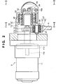
- a starter motor 11 and solenoid 12 form a unit in a single case 13.
- the case 13 includes a housing 14 and cover 15.
- the starter motor 11 is attached to the housing 14, and the solenoid 12 is attached to the cover 15.
- the starter motor 11 has a planetary gear type reduction mechanism 11c between an incorporated rotating shaft 11a and outwardly projecting output shaft 11b.
- a pinion 16 is integrally fixed to the output shaft 11b.
- An idle gear 17 constantly meshes with the pinion 16.
- the idle gear 17 is formed of two coaxial parallel gears 18 and 19, as will be described later in detail, and is rotatably supported by a shaft 21 projecting vertically from a swing arm 20.
- the swing arm 20 has a cylindrical boss 22.
- the boss 22 is rotatably supported by the cover 15 through bearings 23, so that the swing arm 20 can swing about the boss 22 as the center. In this case, the rotation center of the boss 22 and the rotation center of the output shaft 11b of the starter motor 11 coincide with each other.
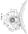
- the idle gear 17, while meshing with the pinion 16 moves around the pinion 16 as it forms an arcuate locus about the rotation center of the pinion 16 as the center.
- An arrow X shown in Figs. 3 to 5 indicates the rotational direction of the ring gear 5.
- a point A shown in Figs. 4 and 5 indicates the position of the pin 25, that is, the connecting point of the cylindrical boss 22 and plunger 24.
- a projection 20a is formed on the swing arm 20.
- the projection 20a abuts against a stopper portion 30 provided to the housing 14, any further swing of the swing arm 20 is regulated.
- the stopper portion 30 is formed of the end of a bolt threadably engaging with a nut fixed to the housing 14.
- the meshing position (meshing degree) of the idle gear 17 with the ring gear 5 can be adjusted.
- the idle gear 17 driven by the starter motor 11 is moved in the radial direction of the ring gear 5 from outside the ring gear 5, so that it meshes with the ring gear 5. Tooth collision occurs at a lower probability than in a conventional case wherein the pinion 16 is moved in the axial direction and is meshed with the ring gear 5. The impact of collision decreases, so that collision noise decreases. In this case, only the idle gear 17 needs to be moved in the radial direction V from outside the ring gear 5. Therefore, complicated and fine electrical control of the starter motor 11 of meshing the pinion 16 with the ring gear 5 while rotating the pinion 16 for a small amount, as in the conventional case, need not be performed.
- the idle gear 17 is moved along the arcuate path.
- the present invention is not limited this, and the idle gear 17 may be moved along, e.g., a linear path.
- the starter motor 11 need not have a movable structure.
- the present invention is not limited to this.
- the idle gear 17 may not be employed, and the pinion 16 which is directly driven by the starter motor 11 may be moved in the radial direction from outside the ring gear 5, so that the pinion 16 meshes with the ring gear 5.
- the idle gear 17 When the idle gear 17 is to be moved in the direction of the arrow V to mesh with the ring gear 5, it is moved in such a direction that its teeth bite those of the ring gear 5. Even if the solenoid (actuator) 12 is turned off after the two gears 17 and 5 mesh with each other, they do not disengage from each other. Thus, when the idle gear 17 is to be preset for a quick start, the solenoid 12 need not be kept on for a long period of time for the purpose of keeping the idle gear 17 to mesh with the ring gear 5 throughout idling stop. Hence, an increase in energy consumption is avoided.
- the idle gear 17 meshing with the ring gear 5 receives the rotation of the ring gear 5 and is sprung back by it to naturally disengage from it in the direction of an arrow W.
- the solenoid 12 need not move the idle gear 17 in the direction W to disengage from the ring gear 5. An increase in energy consumption is avoided in this respect as well.
- the starter motor 11 and solenoid 12 form a unit in the single case 13, and the resultant unit is attached to the side surface of the cylinder block at the connecting portion of the engine main body and the automatic transmission 2. Therefore, the starter unit 3 can be arranged in the rear portion of the engine main body in an ordinary manner.
- the length of the engine 1 in the vertical direction (the direction of the cylinder train or the axial direction of the crankshaft) does not increase, and downsizing of the engine 1 is not hindered.
- the idle gear 17 employs a so-called scissors gear including two gears, i.e., the first and second gears 18 and 19.
- a relatively narrow pitch P2 is formed between the teeth of the first gear (main body gear) 18 and the teeth of the second gear (auxiliary gear) 19.
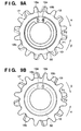
- the idle gear 17 is formed of two gears, i.e., the main body gear 18 and auxiliary gear 19 that are coaxially, rotatably mounted on the shaft 21, as shown in Fig. 2 and Figs. 9A and 9B in detail.
- the auxiliary gear 19 on the rear side of the starter 3 has almost the same shape as that of the main body gear 18, but its teeth lack alternately.
- the two gears 18 and 19 are biased by an annular leaf spring 50 in rotational directions ⁇ and ⁇ , respectively.
- the leaf spring 50 is interposed between the opposing surfaces of the two gears 18 and 19.
- the two ends of the leaf spring 50 are respectively locked by pins 18a and 19a vertically extending from the opposing surfaces of the two gears 18 and 19, respectively.
- the leaf spring 50 exerts its biasing force in a direction to reduce its diameter, so that the pins 18a and 19a may come close to each other.
- the teeth of the two gears 18 and 19 cause a phase shift in the circumferential directions.
- the teeth of the auxiliary gear 19 project from those of the main body gear 18 by a predetermined amount and forms the narrow-pitch portion P2. That portion of the auxiliary gear 19 where a tooth lacks remains as a wide-pitch portion P1.
- the idle gear 17 has regulating means for determining the projecting amount (phase shift amount) of the teeth of the auxiliary gear 19.
- the regulating means is formed of a step or the like formed in the own gear and functions to abut against the pin of the opponent gear, so the opponent gear will not rotate any further.
- the relatively wide pitch P1 formed by the teeth of the main body gear 18 is substantially the same as the pitch of the ring gear 5.
- both of the two gears 18 and 19 of the idle gear 17 mesh with the ring gear 5, but the pinion 16 meshes with only the main body gear 18.
- a meshing portion adjusting means 40 is provided.
- the meshing portion adjusting means 40 adjusts the phase (rotational posture) of the idle gear 17 while the idle gear 17 is being moved toward the ring gear 5 along the arcuate path, such that the idle gear 17 always encounters and meshes with the ring gear 5 at the relatively-small-pitch portion P2 formed by the tooth of the main body gear 18 and that of the auxiliary gear 19.
- the means 40 includes a baffle lever (baffle plate) 41 which abuts against the idle gear 17, moving in the direction V toward the ring gear 5, and determines the phase of the idle gear 17.
- the lever 41 has advanced to the arcuate path of the idle gear 17 and is scarcely in contact with the tooth peak of the idle gear 17.
- the baffle lever 41 is rotatably attached to the housing 14 through a pin 43. As shown in Figs. 11 and 12 as well, the baffle lever 41 is biased in a direction to advance to the arcuate moving path of the idle gear 17 by a coil spring 44 wound around the pin 43.
- a stopper pin 42 which regulates the advancement of the baffle lever 41 to the moving path exceeding a predetermined amount extends from an appropriate portion (e.g., a cylinder block).
- the baffle lever 41 is arranged on a side comparatively close to the front side of the starter 3, and can abut against only the main body gear 18 (in more detail, the teeth of the main body gear 18) of the idle gear 17.
- every other tooth of the main body gear 18 forms a notch 18b, and the baffle lever 41 abuts against every other tooth of the main body gear 18.
- the notches 18b are formed in those teeth of the main body gear 18 for which corresponding teeth of the auxiliary gear 19 exist.
- the baffle lever 41 passes by those teeth of the main body gear 18 which have notches 18b, and abuts against those teeth of the main body gear 18 which have no notches 18b (those teeth of the main body gear 18 for which corresponding teeth of the auxiliary gear 19 do not exist).
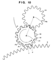
- the idle gear 17 receives a rotation force in the direction of the arrow f from the baffle lever 41 due to the swing propulsive in the direction V, so that its phase is adjusted (its rotational posture is corrected).
- rotation of the pinion 16 in a direction e which is exerted by the idle gear 17 when the idle gear 17 abuts against the baffle lever 41 while it moves in the direction V toward the ring gear 5, is allowed.
- the idle gear 17 is pressed by the baffle lever 41 and rotates reliably before it meshes with the ring gear 5, and its phase is adjusted.
- the idle gear 17 swings in the direction V while it turns again in the direction g from the adjusted phase (rotational posture) as the start point.
- the idle gear 17 when meshing with the ring gear 5, the idle gear 17 always encounters the ring gear 5 at the relatively-narrow-pitch portion P2 formed by a tooth of the main gear 18 and that of the gear 19.
- smooth, good meshing is achieved.
- a one-way clutch 60 provided between the pinion 16, with which the idle gear 17 meshes, and the starter motor 11 will be described from Fig. 13.
- the one-way clutch 60 is locked when rotation is transmitted from the starter motor 11 side (rotating shaft 11a side) to the pinion 16 side (output shaft 11b) in the direction of start of the engine 1, and is set free when rotation is transmitted from the pinion 16 side to the starter motor 11 side in the direction of start of the engine 1. More specifically, the one-way clutch 60 is originally provided to prevent excessive rotation of the starter motor 11, upon reception of high-speed rotation of the engine 1, after complete explosion occurs in the engine 1 and the engine 1 is started, so that the durability of the starter motor 11 is improved.
- the one-way clutch 60 is provided to the planetary gear type reduction mechanism 11c provided between the pinion 16 (output shaft 11b) and starter motor 11 (rotating shaft 11a).
- the sun gear of the reduction mechanism 11c is connected to the rotating shaft 11a of the starter motor 11.
- a plurality of planetary gears mesh with the sun gear and an internal gear (inner tooth ring gear) 11d, and the carrier of the planetary gears is connected to the output shaft 11b of the starter motor 11 and the pinion 16.
- the sun gear 11a rotates in the direction of an arrow a .
- the planetary gears turn in the direction of an arrow b, and the internal gear 11d tends to rotate in the direction of an arrow c.
- the one-way clutch 60 regulates rotation of the internal gear 11d in the direction of the arrow c.
- the carrier or pinion 16 rotates in the direction of an arrow e.
- the idle gear 17 rotates in the direction f.
- the ring gear 5 of the crankshaft rotates in the direction of the arrow X.
- the idle gear 17 swings in the direction V from the phase (rotational posture) at the time point when abutment is canceled as the start point, while it rotates in the direction of the arrow g again, as shown in Fig. 16.
- the rotating shaft 11a of the starter motor 11 does not receive high-speed rotation from the engine 1 side, and its durability is secured. This is an operation effected when the idle gear 17 abuts against the baffle lever 41 in the direction W while it is kept rotatably driven by the ring gear 5 at speed higher than the rotational speed with which it is rotatably driven by the motor 11.
- a return spring having change points on a side to bias the swing arm 20 in the direction V and on a side to bias the swing arm 20 in the direction W, respectively, may be provided to the swing arm 20, so that the idle gear 17 is stably kept at the meshing position even after the solenoid 12 is turned off. Note that the return spring should not interfere with the movement of the swing arm 20 in the separating direction W.
- an engine starting system in which complicated electrical control of the starter motor is avoided and which can realize a silent start that does not hinder downsizing of the engine and a quick start that does not increase energy consumption.
- This system has a wide industrial applicability in the technical field of the engine starting system as a whole, e.g., an idling stop vehicle.
- the gear driven by the starter motor is moved in the radial direction of the ring gear from outside the ring gear, so that it meshes with the ring gear. Tooth collision occurs at a lower probability than in a conventional case wherein the driven gear is moved in the axial direction and is meshed with the ring gear. The impact of collision decreases, so that collision noise decreases. In this case, only the driven gear needs to be moved in the radial direction from outside the ring gear. Therefore, complicated and fine electrical control of the starter motor of meshing the driven gear with the ring gear while rotating the driven gear for a small amount, as in the conventional case, need not be performed.
- the driven gear may be a pinion directly driven by the starter motor, or an idle gear or intermediate gear rotated by the pinion.
- the movement of the driven gear in the radial direction may draw a linear locus, an arcuate locus, or the like.
- the idle gear rotated as the driven gear by the pinion is employed, and the idle gear is moved in the radial direction to draw an arcuate locus.
- the starter motor need not have a movable structure.
- the idle gear meshing with the ring gear naturally disengages from the ring gear.
- the actuator need not move the idle gear in the direction to disengage from the ring gear.
- the idle gear when the idle gear is to mesh with the ring gear, the idle gear is moved in such a direction that its tooth bites in the tooth of the ring gear.
- the actuator such as a solenoid need not be kept on for a long period of time for the purpose of keeping the idle gear to mesh with the ring gear throughout idling stop. Therefore, energy consumption does not increase.
- the idle gear and auxiliary gear forms a so-called scissors gear structure. Portions having different tooth pitches are formed in the idle gear.
- the idle gear encounters the ring gear and meshes with it at a relatively-narrow-pitch portion. Thus, a tooth of the idle gear and a corresponding tooth of the ring gear mesh reliably and smoothly.
- the phase of the idle gear is adjusted on the arcuate moving path.
- a tooth of the idle gear and a corresponding tooth of the ring gear mesh more reliably and smoothly.
- the idle gear Because of the propulsive generated when the idle gear moves toward the ring gear, the idle gear is pressed by the abutting member and rotates, so that its phase is adjusted.
- Rotation of the pinion is regulated and allowed in the above manner by utilizing the one-way clutch which is originally provided between the pinion and starter motor in order to prevent the starter motor from rotating excessively due to the high-speed rotation of the engine after engine start.
- a dedicated mechanism for regulating and allowing rotation of the pinion can be omitted, and accordingly the number of components and cost can be decreased.
- the starter unit can be disposed in the rear portion of the engine main body in the ordinary manner, the length of the engine in the direction of the cylinder train (axial direction of the crankshaft) does not increase, and downsizing of the engine is not hindered.
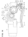
- Fig. 18 is a view for explaining the arrangement of the starting system according to this embodiment.
- a pinion gear 16 is caused to mesh with a ring gear 5 through an idle gear 17 which moves in the radial direction toward the ring gear 5.
- a lever-like baffle member 140 is provided as a means for adjusting the phase (rotational posture) in the rotational direction of the idle gear 17 while the idle gear 17 is moved toward the ring gear 5 along an arcuate path, so that the idle gear 17 abuts against and meshes with the ring gear 5 reliably in a phase-set state with the ring gear 5.
- the baffle member 140 has first arm portion 142 and second arm portion 143 which form a predetermined angle about a support shaft 141 (support portion) as the center, and is rotatably supported by the support shaft 141.
- the first and second arm portions 142 and 143 can integrally swing about the support shaft 141 as the center.
- the baffle member 140 has a double-spring-structure spring-back mechanism constituted by a first spring 144 (coil spring), pin-like first spring stopper 145, and second spring 146 (coil spring).
- the first spring 144 biases the baffle member 140 in a direction to separate from the ring gear 5, so that the baffle member 140 is returned to the retreat position and held at the retreat position.
- the first spring stopper 145 abuts against the first spring 144 and prohibits the baffle member 140 from being moved in the counter ring gear direction over the retreat position by the spring force (biasing force) of the first spring 144.
- the second spring 146 biases the baffle member 140 in a direction to abut against the ring gear 5 with a spring force smaller than that of the first spring 144.
- the first and second springs 144 and 146 are arranged such that they are wound around the support shaft 141 in opposite directions with their ends extending in the radial direction.
- the first spring stopper 145 is fixed to a bracket 6 that attaches a case 13 of a starter 3 to the engine main body.
- a pin-like second spring stopper 147 is fixed to the bracket 6.
- a pin-like third spring stopper 148 is fixed to the first arm portion 142 of the baffle member 140.
- the respective ends of the first spring 144 which extend in the radial direction abut against the second and third spring stoppers 147 and 148 from the ring gear 5 side.
- the respective ends of the second spring 146 which extend in the radial direction abut against the second and third spring stoppers 147 and 148 from the counter ring gear 5 side.
- the distal end of the first arm portion 142 can abut against the tooth surface of the idle gear 17. While the first arm portion 142 is in abutment against the tooth surface of the idle gear 17, when the baffle member 140 rotates as it is pressed by the idle gear 17 moving toward the ring gear 5, the second arm portion 143 can abut against the tooth surface of the ring gear 5.
- auxiliary arm member 149 is pivotally supported, through a shaft pin 150, on the main body portion of the second arm portion 143 which rotates together with the first arm portion 142.
- the auxiliary arm member 149 is biased by a spring 151 (coil spring) in such a direction that it becomes integral with the main body portion.
- the idle gear 17 has a main body gear portion 18 which can mesh with the pinion gear 16 and ring gear 5, and an auxiliary gear portion 19 which is coaxial with the main body gear portion 18, has substantially the same diameter and almost the same tooth form as those of the main body gear portion 18, but lacks every other tooth.
- the main body gear portion 18 and auxiliary gear portion 19 form a so-called scissors gear.
- the main body gear portion 18 and auxiliary gear portion 19 are biased by a biasing means (not shown; a leaf spring or the like) such that they are relatively shifted from each other by a predetermined phase in the rotational direction.
- the teeth of the auxiliary gear portion 19 project in the circumferential direction by a predetermined amount while they partially overlap every other tooth of the main body gear portion 18, so that they each form a relatively-short-pitch portion with respect to that next tooth of the main body gear portion 18 which does not overlap the auxiliary gear portion 19.
- the portion between that tooth of the main body gear portion 18 which does not overlap the auxiliary gear portion 19 and the next tooth of the auxiliary gear portion 19 forms a relatively-long-pitch portion.
- the repetition of the relatively-short-pitch portion and relatively-long-pitch portion forms alternate relatively-long-tooth-pitch portion and relatively-short-tooth-pitch portion in the idle gear 17 as a whole.
- the relatively long pitch between the teeth of the main body gear portion 18 is substantially the same as the pitch of the teeth of the ring gear 5.
- main body gear portion 18 and auxiliary gear portion 19 mesh with the ring gear 5, and the pinion gear 16 meshes with only the main body gear portion 18.
- the baffle member 140 (in more detail, the first arm portion 142) abuts against only the main body gear portion 18 of the idle gear 17.
- every other tooth of the main body gear portion 18 of the idle gear 17 forms a notch 18b that clears abutment with the baffle member 140.
- the notches 18b are formed in those teeth of the main body gear portion 18 which partially overlap the teeth of the auxiliary gear portion 19.
- the pinion gear 16 integral with an output shaft 11b of a starter motor 11 is meshed with the ring gear 5 integral with the output shaft (crankshaft) of an engine 1, so that the engine 1 is started.
- the starter motor 11 and a solenoid 12 are not energized.
- the idle gear 17 is located at a retreat position remote from the ring gear 5 in the radial direction.
- the baffle member 140 is separated from the ring gear 5.
- the solenoid 12 When the engine 1 is stopped, the solenoid 12 is energized immediately and its plunger 24 is pulled in. Thus, a swing arm 20 swings in a direction to come close to the solenoid 12. Accordingly, as shown in Fig. 19, the idle gear 17 moves from the retreat position (T1) toward the ring gear 5 in the stopped state, meshes with the stopped pinion gear 16, and swings while rotating (turning) in one direction (clockwise in Fig. 19).
- the baffle member 140 rotates such that the first arm portion 142 passes by that tooth of the main body gear portion 18 of the idle gear 17 which has a notch 18b, and abuts against that tooth (a tooth which partially overlaps the auxiliary gear portion 19) of the main body gear portion 18 which does not have a notch 18b, until a position where the second arm portion 143 abuts against the tooth surface of the ring gear 5, as shown in Fig. 19.
- the idle gear 17 After the second arm portion 143 of the baffle member 140 abuts against the tooth surface of the ring gear 5, the idle gear 17 further moves toward the ring gear 5, and the first arm portion 142 of the baffle member 140 abuts against the tooth surface of that tooth (a tooth which partially overlaps the auxiliary gear portion 19) of the main body gear portion 18 of the idle gear 17 which does not have a notch 18b.
- the idle gear 17 rotates (turns) in the reverse direction (counterclockwise in Fig. 19) while rotating the pinion gear 16 in a direction to rotate freely (clockwise in Fig. 19), and is adjusted to have such a phase that it can reliably mesh with the ring gear 5.
- ⁇ 1 denotes the angle of a certain tooth of the idle gear 17, when it finally meshes with the ring gear 5, with reference to a line A that connects the center of the idle gear 17 and that of the ring gear 5.
- Reference symbol ⁇ 1 denotes the angle (phase) of the tooth (that tooth of the main body gear portion 18 which does not have a notch 18b), at a preceding time point where the phase of the idle gear 17 is adjusted, which abuts against the first arm portion 142 of the baffle member 140 with reference to a line B that connects the center of the pinion gear 16 and that of the idle gear 17.
- the angle of a certain tooth of the idle gear 17, when it finally meshes with the ring gear 5, with reference to the line A that connects the center of the idle gear 17 and that of the ring gear 5 differs each time.
- the angle (phase) of the tooth that tooth of the main body gear portion 18 which does not have a notch 18b
- the angle (phase) of the tooth which abuts against the first arm portion 142 of the baffle member 140, at a time point where the phase of the idle gear 17 is adjusted by the operation of the baffle member 140, with reference to the line B that connects the center of the pinion gear 16 and that of the idle gear 17 changes to ⁇ 2.
- the idle gear 17 swings toward the ring gear 5 while it rotates (turns) again in the initial direction from the adjusted phase as the start point.
- the idle gear 17 encounters the ring gear 5 at the relatively-short-pitch portion between the tooth of the main body gear portion 18 and the corresponding tooth of the auxiliary gear portion 19, and meshes with it reliably and smoothly.
- the swing arm 20 abuts against a stopper portion (not shown) provided to the housing 14, so that its swing is regulated at a predetermined position.
- the positional relationship among the support shaft 141 and first and second arm portions 142 and 143 of the baffle member 140 is set such that, after the second arm portion 143 abuts against the tooth surface of the ring gear 5, when the first arm portion 142 presses the tooth surface of that tooth of the main body gear portion 18 of the idle gear 17 which does not have a notch 18b, the first arm portion 142 swings while rotating (turning) the idle gear 17 in the reverse direction, so the main body gear portion 18 may encounter the ring gear 5 at a relatively-short-pitch portion.
- the planetary gear type reduction mechanism 11c provided between the rotating shaft 11a and output shaft 11b of the starter motor 11 has a one-way clutch (not shown).
- the one-way clutch is locked when rotation is transmitted from the starter motor 11 side (rotating shaft 11a side) to the pinion 16 side (output shaft 11b) in the direction of start of the engine 1, and is set free when rotation is transmitted from the pinion 16 side to the starter motor 11 side in the direction of start of the engine 1.
- the operation that the baffle member 140, after abutting against the ring gear 5, presses the tooth surface of the idle gear 17 to rotate (turn) it in the reverse direction utilizes this one-way clutch.
- rotation of the pinion gear 16 is regulated in the direction of the rotation force which is applied by the idle gear 17 when the idle gear 17 moves toward the ring gear 5.
- Rotation of the pinion gear 16 is allowed in the direction of the rotation force which is applied by the idle gear 17, when the first arm portion 142 of the baffle member 140 abuts against the tooth surface of the idle gear 17 and the second arm portion 143 of the baffle member 140 abuts against the tooth surface of the ring gear 5, while the idle gear 17 moves toward the ring gear 5.
- the idle gear 17 encounters the ring gear 5 at the relatively-short-pitch portion of the main body gear portion 18. Even if the teeth that encounter the first abut against each other with their tooth peaks, when the idle gear 17 further moves, a long-pitch portion comes next, and the tooth peak of the ring gear fits in the tooth space of the idle gear and meshes with it reliably. In this manner, the tooth of the idle gear 17 and that of the ring gear 5 can be meshed more reliably and smoothly.
- the idle gear 17 can prevent backlash due to the original function of the scissors gear. Thus, tooth striking noise can be further decreased.
- the rotation center (the center of the pin 21) of the idle gear 17 is located on the more front side in a rotational direction X of the ring gear 5 than a line L that connects the rotation center (the center of the output shaft 11b) of the pinion gear 16 and that of the ring gear 5.
- the idle gear 17 is swung clockwise in Fig. 19 or 20 to mesh with the ring gear 5, it is moved in such a direction that its tooth bites the tooth of the ring gear 5.
- the second arm portion 143 of the baffle member 140 has the auxiliary arm member 149 as described above.
- the main body portion of the second arm portion 143 and the auxiliary arm member 149 function integrally, as shown in Fig. 21A.
- the auxiliary arm member 149 is pressed by the tooth of the ring gear 5 and pivots with respect to the main body portion of the second arm portion 143, as shown in Fig. 21C, and leaves the tooth space of the ring gear 5, as shown in Fig. 21D. Therefore, defective return caused by interference with the ring gear 5, which occurs when the baffle member 140 returns to the retreat position, can be prevented.
- the idle gear is located at the retreat position remote from the ring gear in the radial direction, and the baffle member is separated from the ring gear.
- the swing mechanism actuates to move the idle gear from the retreat position toward the ring gear in the stopped state.
- the baffle member moves until a position where the second arm portion abuts against the tooth surface of the ring gear, while the first arm portion abuts against the tooth surface of the idle gear. After the second arm portion of the baffle member abuts against the tooth surface of the ring gear, the idle gear further moves toward the ring gear.
- the first arm member of the baffle member which has stopped when the second arm portion abuts against the tooth surface of the ring gear, presses the tooth surface of the idle gear, and rotates (turns) the idle gear.
- the idle gear is adjusted through the baffle member such that it has a predetermined phase in the rotational direction with respect to the ring gear.
- the phase of the idle gear is set, the idle gear abuts against the ring gear and meshes with it.
- pinion gear and ring gear are meshed with each other through the idle gear that moves in the radial direction toward the ring gear, they mesh more smoothly than in a conventional case wherein the pinion gear is moved in the axial direction to mesh with the ring gear, and collision noise is decreased.
- Phase setting of the gear can be realized by a low-cost mechanical means that does not require complicated electrical control, so that the pinion gear and ring gear can be meshed reliably.
- the entire length of the engine is not increased as in a belt-driven starter, so that downsizing of the engine is not hindered.
- a starter motor has a built-in reduction gear such as a planetary gear mechanism.
- the baffle member can be normally abutted against the ring gear mechanically, while it is retreated from the ring gear to ensure durability, by utilizing the movement of the idle gear.
- the mechanism for setting the gear phase can be simplified.
- the main body gear portion and auxiliary gear portion form a so-called scissors gear.
- a relatively-long-tooth-pitch portion and relatively-short-tooth-pitch portion alternate.
- the idle gear encounters the ring gear at the relatively-short-tooth-pitch portion. Even if the teeth that encounter at first abut against each other with their tooth peaks, when the idle gear further moves, a long-pitch portion comes next, and the tooth peak of the ring gear fits in the tooth space of the idle gear and meshes with it reliably. In this manner, the tooth of the idle gear and that of the ring gear can be meshed more reliably and smoothly. Also, backlash can be prevented by the original function of the scissors gear. Thus, tooth striking noise can be further decreased.
- the starting system When the starting system is built as a module on the bracket, the building accuracies of the respective portions of the starting system can be increased, and the starting system can be attached to the engine main body well.
- the baffle member can be reliably restored to the retreat position without interfering with the return of the idle gear, and can be held at the retreat position until restart after the next vehicle standing.
- the baffle member can be reliably abutted against the tooth surface of the idle gear and can be pivoted toward the ring gear, so that the baffle member can be abutted against the tooth surface of the ring gear reliably.
- the retreat position of the baffle member might not be stable.
- the baffle member is regulated by the spring stopper, it is stably held at the retreat position.
- the idle gear swings, it abuts against the baffle member reliably.
- the baffle member has only one second arm portion, when the engine is started, the idle gear is sprung aside, and the baffle member is to separate from the ring gear with the spring force, sometimes the distal end of the second arm portion that has been abutting against the tooth surface of the ring gear is caught by the next tooth of the ring gear on the other side, and cannot return to the retreat position easily.
- the auxiliary arm member is provided, when the baffle member pivots in the direction to abut against the tooth surface of the ring gear, the main body portion and auxiliary arm member of the second arm portion function integrally.
- the idle gear swings while rotating (turning) in one direction.
- the baffle member rotates such that the first arm portion passes by that tooth of the main body gear portion of the idle gear which has a notch, and abuts against that tooth of the main body gear portion which does not have a notch.
- the second arm portion of the baffle member abuts against the tooth surface of the ring gear.
- the pinion gear is then allowed to rotate in the reverse direction, and the first arm portion of the baffle member abuts against the tooth surface of that tooth of the main body gear portion of the idle gear which does not have a notch.
- the idle gear rotates (turns) in the reverse direction while it rotates the pinion gear in a direction (a direction opposite to one direction described above) in which the pinion gear is allowed to rotate freely, and is adjusted to have such a phase that it can reliably mesh with the ring gear.
Landscapes
- Engineering & Computer Science (AREA)
- Chemical & Material Sciences (AREA)
- Combustion & Propulsion (AREA)
- Mechanical Engineering (AREA)
- General Engineering & Computer Science (AREA)
- Connection Of Motors, Electrical Generators, Mechanical Devices, And The Like (AREA)
- Control Of Vehicle Engines Or Engines For Specific Uses (AREA)
Applications Claiming Priority (4)
| Application Number | Priority Date | Filing Date | Title |
|---|---|---|---|
| JP2003179420A JP3901132B2 (ja) | 2003-06-24 | 2003-06-24 | エンジンの始動装置 |
| JP2003179420 | 2003-06-24 | ||
| JP2004021252 | 2004-01-29 | ||
| JP2004021252A JP2005214067A (ja) | 2004-01-29 | 2004-01-29 | エンジンの始動装置 |
Publications (2)
| Publication Number | Publication Date |
|---|---|
| EP1491764A2 true EP1491764A2 (fr) | 2004-12-29 |
| EP1491764A3 EP1491764A3 (fr) | 2008-08-06 |
Family
ID=33422191
Family Applications (1)
| Application Number | Title | Priority Date | Filing Date |
|---|---|---|---|
| EP04012462A Withdrawn EP1491764A3 (fr) | 2003-06-24 | 2004-05-26 | Système de démarrage d'un moteur |
Country Status (1)
| Country | Link |
|---|---|
| EP (1) | EP1491764A3 (fr) |
Cited By (7)
| Publication number | Priority date | Publication date | Assignee | Title |
|---|---|---|---|---|
| EP2412968A2 (fr) | 2010-07-27 | 2012-02-01 | Robert Bosch GmbH | Installation de démarrage pour moteurs à combustion interne |
| WO2017108038A1 (fr) * | 2015-12-22 | 2017-06-29 | Schaeffler Technologies AG & Co. KG | Dispositif de démarrage et procédé de démarrage d'un moteur à combustion interne équipé d'un volant à deux masses |
| US9809291B2 (en) | 2008-10-20 | 2017-11-07 | Eric Galloway | Apparatus and method for rotating a shaft |
| US10436169B2 (en) | 2008-12-19 | 2019-10-08 | Seg Automotive Germany Gmbh | Method and device for start-stop systems of internal combustion engines in motor vehicles |
| DE102018218121A1 (de) | 2018-10-23 | 2020-04-23 | Zf Friedrichshafen Ag | Planetengetriebe |
| CN115234421A (zh) * | 2022-09-02 | 2022-10-25 | 宁波市镇海金腾电器有限公司 | 一种转动啮合式起动机 |
| US20250146559A1 (en) * | 2023-06-07 | 2025-05-08 | Harley-Davidson Motor Company, Inc. | Reverse drive assembly for motorized vehicle |
Families Citing this family (1)
| Publication number | Priority date | Publication date | Assignee | Title |
|---|---|---|---|---|
| US20170004406A1 (en) * | 2015-06-30 | 2017-01-05 | Qualcomm Incorporated | Parallel belief space motion planner |
Citations (3)
| Publication number | Priority date | Publication date | Assignee | Title |
|---|---|---|---|---|
| JPH0697023A (ja) | 1992-09-16 | 1994-04-08 | Fujitsu Ltd | 半導体装置の製造方法 |
| JP2002257014A (ja) | 2001-03-06 | 2002-09-11 | Denso Corp | 車両用始動装置 |
| JP2002303236A (ja) | 2001-04-02 | 2002-10-18 | Denso Corp | スタータ |
Family Cites Families (9)
| Publication number | Priority date | Publication date | Assignee | Title |
|---|---|---|---|---|
| US1184866A (en) * | 1914-07-24 | 1916-05-30 | Westinghouse Electric & Mfg Co | Starting mechanism for automobiles. |
| US1327276A (en) * | 1916-08-24 | 1920-01-06 | Hasbrouck Louis Bennett | Starter for internal-combustion engines |
| US1620102A (en) * | 1920-06-11 | 1927-03-08 | Jencick Stephen | Starting device for internal-combustion engines |
| US1533072A (en) * | 1920-10-22 | 1925-04-07 | Ind Res Corp | Electric starter |
| US1710427A (en) * | 1924-10-08 | 1929-04-23 | John A Mcgrew | Entrainment mechanism |
| US1717054A (en) * | 1925-07-08 | 1929-06-11 | Bethlehem Steel Corp | Tractor-truck gearing |
| US2025166A (en) * | 1934-09-22 | 1935-12-24 | Eclipse Aviat Corp | Starter for an engine |
| US2593933A (en) * | 1947-07-03 | 1952-04-22 | Raymond C Strawn | Planetary power transmission device |
| US2905001A (en) * | 1956-09-10 | 1959-09-22 | Ray W Courtney | Engine self-starter |
-
2004
- 2004-05-26 EP EP04012462A patent/EP1491764A3/fr not_active Withdrawn
Patent Citations (3)
| Publication number | Priority date | Publication date | Assignee | Title |
|---|---|---|---|---|
| JPH0697023A (ja) | 1992-09-16 | 1994-04-08 | Fujitsu Ltd | 半導体装置の製造方法 |
| JP2002257014A (ja) | 2001-03-06 | 2002-09-11 | Denso Corp | 車両用始動装置 |
| JP2002303236A (ja) | 2001-04-02 | 2002-10-18 | Denso Corp | スタータ |
Cited By (12)
| Publication number | Priority date | Publication date | Assignee | Title |
|---|---|---|---|---|
| US9809291B2 (en) | 2008-10-20 | 2017-11-07 | Eric Galloway | Apparatus and method for rotating a shaft |
| US10436169B2 (en) | 2008-12-19 | 2019-10-08 | Seg Automotive Germany Gmbh | Method and device for start-stop systems of internal combustion engines in motor vehicles |
| EP2412968A2 (fr) | 2010-07-27 | 2012-02-01 | Robert Bosch GmbH | Installation de démarrage pour moteurs à combustion interne |
| DE102010038441A1 (de) | 2010-07-27 | 2012-02-02 | Robert Bosch Gmbh | Startanlage für Brennkraftmaschinen |
| DE102010038441B4 (de) * | 2010-07-27 | 2021-05-12 | Seg Automotive Germany Gmbh | Startanlage für Brennkraftmaschinen |
| WO2017108038A1 (fr) * | 2015-12-22 | 2017-06-29 | Schaeffler Technologies AG & Co. KG | Dispositif de démarrage et procédé de démarrage d'un moteur à combustion interne équipé d'un volant à deux masses |
| CN108368816A (zh) * | 2015-12-22 | 2018-08-03 | 舍弗勒技术股份两合公司 | 起动装置和用于起动配备有双质量飞轮的内燃机的方法 |
| CN108368816B (zh) * | 2015-12-22 | 2020-12-08 | 舍弗勒技术股份两合公司 | 起动装置和用于起动配备有双质量飞轮的内燃机的方法 |
| DE102018218121A1 (de) | 2018-10-23 | 2020-04-23 | Zf Friedrichshafen Ag | Planetengetriebe |
| CN115234421A (zh) * | 2022-09-02 | 2022-10-25 | 宁波市镇海金腾电器有限公司 | 一种转动啮合式起动机 |
| CN115234421B (zh) * | 2022-09-02 | 2025-02-14 | 宁波市镇海金腾电器有限公司 | 一种转动啮合式起动机 |
| US20250146559A1 (en) * | 2023-06-07 | 2025-05-08 | Harley-Davidson Motor Company, Inc. | Reverse drive assembly for motorized vehicle |
Also Published As
| Publication number | Publication date |
|---|---|
| EP1491764A3 (fr) | 2008-08-06 |
Similar Documents
| Publication | Publication Date | Title |
|---|---|---|
| US6378479B1 (en) | Starting system for internal combustion engine | |
| KR100332136B1 (ko) | 시동 전동기 | |
| US6397808B1 (en) | Engine starter having traction-drive type reduction gear and torque transmitting device for linking the reduction gear and driven shaft of engine | |
| EP1491764A2 (fr) | Système de démarrage d'un moteur | |
| JP3584592B2 (ja) | 一方向クラッチ | |
| US5905309A (en) | Starter with shock absorbing device | |
| EP0649984B1 (fr) | Démarreur à engrenage réducteur épicycloidal | |
| KR20050041942A (ko) | 스타터 | |
| JP4487976B2 (ja) | スタータ | |
| JP4552955B2 (ja) | スタータ | |
| JP2002303236A (ja) | スタータ | |
| US6647812B2 (en) | Starter motor having intermediate gear | |
| US5743139A (en) | Starter with alignment means for planetary gears | |
| JP3555245B2 (ja) | スタータ | |
| US6789438B2 (en) | Engine starting apparatus | |
| JP3901132B2 (ja) | エンジンの始動装置 | |
| US7814807B2 (en) | Engine starter having intermediate gear | |
| US20050109136A1 (en) | Starter for internal combustion engine | |
| US20020029644A1 (en) | Starting apparatus for an internal combustion engine | |
| JP6113252B1 (ja) | エンジン始動装置、及びその製造方法 | |
| JP2009180211A (ja) | スタータ | |
| JP2005214067A (ja) | エンジンの始動装置 | |
| US20080168861A1 (en) | Slotted shift lever plug with multiple pivot positions | |
| JP2006249971A (ja) | エンジンの始動装置 | |
| JP2009216062A (ja) | スタータ |
Legal Events
| Date | Code | Title | Description |
|---|---|---|---|
| PUAI | Public reference made under article 153(3) epc to a published international application that has entered the european phase |
Free format text: ORIGINAL CODE: 0009012 |
|
| AK | Designated contracting states |
Kind code of ref document: A2 Designated state(s): AT BE BG CH CY CZ DE DK EE ES FI FR GB GR HU IE IT LI LU MC NL PL PT RO SE SI SK TR |
|
| AX | Request for extension of the european patent |
Extension state: AL HR LT LV MK |
|
| PUAL | Search report despatched |
Free format text: ORIGINAL CODE: 0009013 |
|
| AK | Designated contracting states |
Kind code of ref document: A3 Designated state(s): AT BE BG CH CY CZ DE DK EE ES FI FR GB GR HU IE IT LI LU MC NL PL PT RO SE SI SK TR |
|
| AX | Request for extension of the european patent |
Extension state: AL HR LT LV MK |
|
| AKX | Designation fees paid | ||
| STAA | Information on the status of an ep patent application or granted ep patent |
Free format text: STATUS: THE APPLICATION IS DEEMED TO BE WITHDRAWN |
|
| 18D | Application deemed to be withdrawn |
Effective date: 20090207 |
|
| REG | Reference to a national code |
Ref country code: DE Ref legal event code: 8566 |