EP1491850B1 - Dispositif de mesure et procédé pour déterminer l'orientation spatiale d'un corps par rapport à deux directions de référence horizontales - Google Patents
Dispositif de mesure et procédé pour déterminer l'orientation spatiale d'un corps par rapport à deux directions de référence horizontales Download PDFInfo
- Publication number
- EP1491850B1 EP1491850B1 EP04003808.5A EP04003808A EP1491850B1 EP 1491850 B1 EP1491850 B1 EP 1491850B1 EP 04003808 A EP04003808 A EP 04003808A EP 1491850 B1 EP1491850 B1 EP 1491850B1
- Authority
- EP
- European Patent Office
- Prior art keywords
- measurement device
- directions
- individual
- inclinometer
- determining
- Prior art date
- Legal status (The legal status is an assumption and is not a legal conclusion. Google has not performed a legal analysis and makes no representation as to the accuracy of the status listed.)
- Expired - Lifetime
Links
- 238000000034 method Methods 0.000 title description 5
- 238000005259 measurement Methods 0.000 claims description 56
- 230000001133 acceleration Effects 0.000 claims description 6
- 238000012935 Averaging Methods 0.000 claims description 5
- 238000004422 calculation algorithm Methods 0.000 claims description 3
- 230000005484 gravity Effects 0.000 claims description 3
- 238000004519 manufacturing process Methods 0.000 claims description 3
- 238000012545 processing Methods 0.000 claims description 3
- 230000003993 interaction Effects 0.000 claims description 2
- 239000002184 metal Substances 0.000 claims description 2
- 239000000123 paper Substances 0.000 claims description 2
- 239000002985 plastic film Substances 0.000 claims description 2
- 229920006255 plastic film Polymers 0.000 claims description 2
- 238000000205 computational method Methods 0.000 claims 1
- 238000004364 calculation method Methods 0.000 description 6
- 230000008901 benefit Effects 0.000 description 5
- 238000006243 chemical reaction Methods 0.000 description 3
- 239000000463 material Substances 0.000 description 3
- 230000003287 optical effect Effects 0.000 description 3
- 238000005096 rolling process Methods 0.000 description 3
- 239000013598 vector Substances 0.000 description 3
- 238000012937 correction Methods 0.000 description 2
- 239000007788 liquid Substances 0.000 description 2
- 230000009471 action Effects 0.000 description 1
- 238000009529 body temperature measurement Methods 0.000 description 1
- 230000008859 change Effects 0.000 description 1
- 239000002131 composite material Substances 0.000 description 1
- 238000010276 construction Methods 0.000 description 1
- 238000000354 decomposition reaction Methods 0.000 description 1
- 238000013461 design Methods 0.000 description 1
- 238000001514 detection method Methods 0.000 description 1
- 238000010586 diagram Methods 0.000 description 1
- 230000000694 effects Effects 0.000 description 1
- 238000001914 filtration Methods 0.000 description 1
- 230000006872 improvement Effects 0.000 description 1
- 230000007774 longterm Effects 0.000 description 1
- 239000011159 matrix material Substances 0.000 description 1
- 239000003208 petroleum Substances 0.000 description 1
- 238000012552 review Methods 0.000 description 1
- 239000007787 solid Substances 0.000 description 1
- 238000007619 statistical method Methods 0.000 description 1
- 230000009885 systemic effect Effects 0.000 description 1
- 230000002123 temporal effect Effects 0.000 description 1
Images


Classifications
-
- G—PHYSICS
- G01—MEASURING; TESTING
- G01B—MEASURING LENGTH, THICKNESS OR SIMILAR LINEAR DIMENSIONS; MEASURING ANGLES; MEASURING AREAS; MEASURING IRREGULARITIES OF SURFACES OR CONTOURS
- G01B21/00—Measuring arrangements or details thereof, where the measuring technique is not covered by the other groups of this subclass, unspecified or not relevant
- G01B21/22—Measuring arrangements or details thereof, where the measuring technique is not covered by the other groups of this subclass, unspecified or not relevant for measuring angles or tapers; for testing the alignment of axes
- G01B21/24—Measuring arrangements or details thereof, where the measuring technique is not covered by the other groups of this subclass, unspecified or not relevant for measuring angles or tapers; for testing the alignment of axes for testing alignment of axes
-
- G—PHYSICS
- G01—MEASURING; TESTING
- G01C—MEASURING DISTANCES, LEVELS OR BEARINGS; SURVEYING; NAVIGATION; GYROSCOPIC INSTRUMENTS; PHOTOGRAMMETRY OR VIDEOGRAMMETRY
- G01C19/00—Gyroscopes; Turn-sensitive devices using vibrating masses; Turn-sensitive devices without moving masses; Measuring angular rate using gyroscopic effects
- G01C19/02—Rotary gyroscopes
- G01C19/04—Details
- G01C19/30—Erection devices, i.e. devices for restoring rotor axis to a desired position
-
- G—PHYSICS
- G01—MEASURING; TESTING
- G01C—MEASURING DISTANCES, LEVELS OR BEARINGS; SURVEYING; NAVIGATION; GYROSCOPIC INSTRUMENTS; PHOTOGRAMMETRY OR VIDEOGRAMMETRY
- G01C9/00—Measuring inclination, e.g. by clinometers, by levels
Definitions
- the invention relates to a measuring device for the precise determination of the spatial orientation of a body relative to two horizontal reference directions, so that the determination of both a pitch and a roll angle can be performed in an improved and very accurate manner.
- the body should be stored fixed space and immobile to perform the measurement, at least may (and must) during the execution of the measurement on the body only the gravitational act on this.
- the invention is not suitable for applications in weightlessness in space.
- the invention relates to the use of the measuring device for determining two components of the spatial orientation of machines or machine elements, such as e.g. Rolling or rolling, as well as providing correction information to bring misaligned machines or machine elements into an aligned position, and also the use of the measuring device for direction detection on other objects.
- the US 5191713 discloses a method in which a total of 12 inclinometers are used on a ship to measure the location of multiple platforms as well as a reference platform.
- gyro-based directional gauges are in the DE 100 60 974 of August 30, 2001.
- the device is intended to be positioned by means of an adapter on the front ends of rollers can; It is additionally equipped with a laser-based position measuring device.
- the stated task is based on the invention described in the present application.
- the invention solves the problem at hand by providing a redundant design of a two-dimensional sensing direction measuring system equipped with inclinometers so that its functional properties are improved both in terms of operational reliability and, in particular, accuracy. At the same time, if less accurate and thus less expensive individual systems are used, the production costs of the entire system are reduced.
- the invention instead of an inclinometer system comprising two orthogonally oriented single inclinometers, the invention provides for such a system which consists of at least three, preferably four or further individual inclinometers.
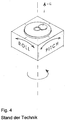
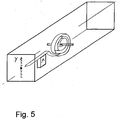
- These are preferably MEMS inclinometers which individually can not indicate the direction of acceleration (unlike simple liquid inclinometers according to US Pat Fig. 3 and 4 ), but are suitable for determining the size of an associated acceleration component, as shown in FIG Fig. 5 is indicated by the simple spring-mass combination shown. -
- Measuring device for determining the spatial orientation of a body relative to two in one, in particular horizontal, plane reference directions, with a housing for application to a surface or to an edge of a body to be measured, with a plurality of inclinometer systems for determining stable spatial positions or of Tilting or rotational movements relative to predefined inertial directions, wherein at least four or more single inclinometers are provided within the housing, whose respective reference or effective direction for detecting a proportion of gravitational acceleration are oriented in different directions of the space, and wherein each of the combinations of three to a Inclinometertriade combined single linear meters provides a respective triad measurement result, which identifies the spatial angular orientation of the measuring device or a body contacted with this according to the direction coordinates Roll and Pitch so that several triad measurement results can be determined; so that further from several triad measurement results by averaging or other calculation methods, a measurement result total measurement result can be provided, which identifies a more accurate angular orientation of the instrument or
- the invention further relates to the use of this measuring device according to claim 9.
- a computationally interesting embodiment of the invention consists, for example, of eight single linear meters arranged symmetrically about an axis or about a center. Regardless of whether they are low-cost or high-quality single inclinometers, disproportionately improved accuracies can be provided in any case by combining a large number of identical or differently constructed individual inclinometers, since it is sometimes possible to determine temperature and compensate for gravity effects by subtraction, averaging or other statistical considerations.
- a measuring device for determining the spatial orientation of a body relative to two reference directions lying in a horizontal plane comprising a housing for application to a surface of a body to be measured, within which a plurality of individual inclinometers for determining a proportional value the gravitational acceleration is provided with respect to respective axes of symmetry associated with the individual inclinometers, and wherein the measuring device is characterized in that at least three, but preferably four or many further, single inclinometers are provided within the housing, which are oriented as non-coplanar as possible in different spatial directions are aligned, and wherein all combinations of three non-coplanar oriented, to a so-called.
- Einzelinclinometer provide a first measurement result, which is the spatial angular Orientation of the measuring device or a body contacted with this according to the two spatial coordinates "roll" and "" Pitch identifies.
- This arrangement according to the invention is used so that initially a plurality of measurement results of the first kind is provided, and then from the plurality of measurement results of the first kind in addition a total measurement result (ie measurement result of the second kind) is determined, which in comparison to the individual measurement results of the first kind indicates a significantly more accurate angular orientation of the meter or a contacted with this body.
- a significantly more accurate measurement result can be immediately provided from the plurality of measurement results of the first type using a suitable mathematical algorithm such as SVD (singular matrix decomposition).
- the number of eight individual inclinometer systems within an overall system according to the invention is to be understood as an example only. It can also be four, five, six, etc.
- Inclinometer or a significantly larger number are used, for example, 150 to 400 miniaturized elements of this type, in particular those whose output varies substantially sinusoidally over the pitch and roll angle, or which can be compensated according to a correction value table accordingly.
- the selected number of single Inclinometer should lead to a compromise in terms of equipment complexity and achievable accuracy increase. Such a compromise obviously also depends on what proportion of costs is to be estimated for a required additional arithmetic unit for calculating the desired overall result.
- MEMS inclinometer in the cost range of currently about EUR 5 .-- per copy
- the individual inclinometers should preferably provide a pulse code modulated output signal.
- the so-called multiplexing or the use of a variety of conventional analog-to-digital converters can be avoided. This is best done in a conventional manner using digital so-called timer / counter components, especially using commercially available miniaturized precision timer with accuracies of in the range of at least 10 (E-6) or better.
- the individual systems provided symmetrically about a single preferred axis. It is also possible to distribute the orientation of the individual systems according to symmetry directions of a regular polyhedron, or approximately statistically over the solid angle (4 * Pi).
- the individual orientations of the individual systems with respect to a device-fixed coordinate system are sufficiently fixed and experienced even small thermally induced changes in direction within the housing.
- the construction of the housing must be sufficiently dimensionally stable.
- it is important that the direction vectors associated with each three individual inclinometers are not spatially coplanar.
- the measured values which are determined by the Einzelinclinometern typically in a skewed three-dimensional coordinate system, converted to a rectangular Cartesian coordinate system.
- the calculation methods for such a conversion are on known.
- output measured values can be expressed, for example, in two of the three Euler angles (namely, pitch and roll pitch) with respect to such a rectangular coordinate system.
- a provision of a measured value for the yaw angle (yaw) by means of inclinometer alone is obviously not possible.
- the said conversion is made, as well as the statistical calculations, by a computer provided in an enclosing housing of the measuring device. To save supply power whose clock frequency can be reduced as soon as it is clear that no current measurement is to be performed. This may be due, for example, to the fact that a sensed spatial position of the device according to the invention does not change and can be assumed to be stable.
- Fig. 1 can be defined, defined directions for the housing of a measuring device of the type presented here with respect to a device fixed predetermined xyz coordinate system, for example, defined by a pyramid.
- Their side surfaces 1, 2, 3, 4, 5, 6 and 7 have a common corner S and bottom edges 21, 22, 23, 24, 25, 26 and 27, which define the base of the pyramid.
- the individual side surfaces thus differ clearly in their directional cosine values.
- a single side surface reference numerals 1 to 7
- a single, eg micromechanical or thermodynamically functioning inclinometer is attached (reference numerals 11, 12, 13, 14, 17; the remaining four single inclinometers are not shown for reasons of clarity).
- a single inclinometer can then be identified with respect to its own coordinate system by at least one vector, each defining a systemic direction of action. This may be, for example or preferably, a normal vector which is then perpendicular to, or optionally parallel, to the relevant side surface of the pyramid.
- the directional cosine values or other useful directional characteristics for specifying a significant reference direction of the individual inclinometers relative to the xyz coordinate system shown may be specified.
- a rotational or tilting movement of the device-fixed coordinate system can thus be measured according to two axes of the space.
- the measurement result can be displayed after conversion in the form of pitch and roll values.
- the ratio of the height h to the radius r of an underlying pyramidal body should have a value of approximately 0.2 to 1.2 in the arrangement shown.
- a preferred value is 0.55.
- gauges of the generic type as they are used for measuring roles in paper and rolling mills, anyway of rather elongated shape and therefore room for a relatively large number of individual Inclinometersysteme, with different orientation relative to Housing of such a meter, offer.
- eight single inclinometers lie on the faces of a regular octahedron (generally: k single inclinometers parallel or normal to the faces, sides, bisectors, and / or corners of a regular polyhedron) Differences in direction between the individual inclinometers are on average greater than those in Fig. 1 shown arrangement. Moreover, the calculation of the different inclinometer combinations is simplified on the basis of symmetry properties, so that such an arrangement works even more efficiently, ie provides a further improved measurement result with little increase in material expenditure; etc.
- an overall system is composed of a housing 100, inclinometers 11 to incl. 17 arranged individually in this housing, a computer 50 for interrogating the signals emitted by the inclinometers and for determining a result in the form of an orientation value. This result can be displayed on a viewing screen 70.
- the Operation of the overall system is preferably by means of a keyboard 60, although other input means (mouse, trackball, stylus, speech, etc.) may be provided.
- the entire system is preferably powered by a battery or accumulator 80, if necessary, a network connection can be provided.
- the proposed Anor Aunt can be operated as described on its own. However, it is used with particular advantage in interaction with a similarly working combination of gyroscopes, especially MEMS gyroscopes incl.
- Thermodynamically operating gyroscopes which is arranged within a common housing. With such a gyroscope combination, it is known to be possible to measure not only the pitch and roll inclination values, but also to detect the yaw azimuth value.
- the mentioned inclusions and azimuth values are subject to disturbing drift errors.
- the inclinometer device presented according to the present invention operates statically, its drift over time is much smaller than with a gyroscope.
- a combination of inclinometers and gyroscopes can be temporarily fixed again and again for a while (and then accurately register the magnitude and direction of gravitational acceleration), the two components can The roll and pitch of the gyroscope values are corrected by the respective components of the inclinometer values, ie they are "supported". In this way, an additional estimate can be made to what extent the yaw value provided by the gyroscopes can be reduced to a presumed best value.
- the measuring device is to compare a current gyroscope-based directional measurement with respect to its azimuthal (yaw) rotational movement to a presumed best value in the fastest possible sequence using current inclinometer-based roll and pitch direction measurement results, the presumed best value being based on a predefined or adaptable Algorithm is calculated.
- Said adaption may, for example, be carried out using temperature measurements on the individual sensors or within the device, or on the basis of a quality estimate for a measurement carried out.
- a significant improvement of said gyroscope-based directional measurement is achieved, typically by at least an order of magnitude.
- the invention is preferably used in the surveying of buildings, of machine tools, or on machines which serve for the production or processing of metal, paper or plastic films. Furthermore, the invention is used with very particular advantage in equipment that serve petroleum prospecting or promotion.
Landscapes
- Physics & Mathematics (AREA)
- General Physics & Mathematics (AREA)
- Engineering & Computer Science (AREA)
- Radar, Positioning & Navigation (AREA)
- Remote Sensing (AREA)
- Length Measuring Devices With Unspecified Measuring Means (AREA)
Claims (13)
- Appareil de mesure destiné à déterminer l'orientation spatiale d'un corps par rapport à deux directions de référence situées dans un plan, notamment dans un plan horizontal, et présentant
un boîtier (100) destiné à être placé sur une surface ou une arête d'un corps à mesurer,
plusieurs systèmes d'inclinomètre (11, 12, 13, 14, 15, 16, 17) déterminant des positions spatiales stables ou des déplacements d'inclinaison ou de rotation par rapport à des directions inertielles prédéfinies,
au moins quatre inclinomètres (11, 12, 13, 14, 15, 16, 17) ou davantage étant prévus à l'intérieur du boîtier et leurs directions de référence ou d'action étant orientées dans différentes directions de l'espace pour saisir une partie de l'accélération gravitationnelle,
l'une des combinaisons de trois inclinomètres (11, 12, 13, 14, 15, 16, 17) rassemblés en un trio d'inclinomètres délivrant un résultat de mesure de trio qui présente l'orientation angulaire spatiale de l'appareil de mesure ou d'un corps en contact avec ce dernier selon les coordonnées directionnelles de roulis et de tangage de telle sorte que plusieurs résultats de mesure de trio puissent être déterminés et qu'à partir de plusieurs résultats de mesure de trio, un résultat de mesure global qui représente une orientation angulaire de l'appareil de mesure ou d'un corps en contact avec ce dernier par rapport auxdites coordonnées directionnelles de roulis et de tangage plus précise que des résultats de mesure de trio distincts puisse être préparé par formation d'une valeur moyenne ou autre procédé de calcul. - Appareil de mesure selon la revendication 1, dans lequel les différentes directions de référence se rapportent à un point de symétrie et correspondent essentiellement aux directions des normales aux surfaces d'un polyèdre régulier qui présente la forme d'un tétraèdre ou d'un octaèdre.
- Appareil de mesure selon la revendication 1, dans lequel les différentes directions de référence sont situées sur une ligne de l'espace et correspondent essentiellement aux directions définies par les normales aux surfaces latérales (1, 2, 3, 4, 5, 6, 7) d'une pyramide comptant au moins quatre côtés.
- Appareil de mesure selon la revendication 1, dans lequel les différentes directions de référence concernent une ligne de l'espace et correspondent essentiellement aux directions définies par les normales aux surfaces latérales (1, 2, 3, 4, 5, 6, 7) d'une pyramide à au moins trois côtés.
- Appareil de mesure selon la revendication 2, dans lequel huit inclinomètres (11, 12, 13, 14, 15, 16, 17) dont les directions de référence ou d'action déterminantes sont parallèles aux normales aux surfaces, aux arêtes (21, 22, 23, 24, 25, 26, 27), aux rayons aux sommets ou aux rayons entre centre et arêtes d'un polyèdre régulier sont prévus.
- Appareil de mesure selon l'une des revendications précédentes, destiné à être utilisé en coopération avec un appareil de mesure de direction basée sur gyroscope et pour soutenir les valeurs de mesure saisies par ce dernier par rapport à une coordonnée de roulis ou une coordonnée de tangage.
- Appareil de mesure selon la revendication 6, dans lequel, lorsque l'appareil de mesure est à un état mécanique de repos, un résultat effectif de mesure de direction basée sur gyroscope, est corrigé en termes du déplacement de rotation azimutal de l'appareil de mesure à l'aide de résultats effectifs de mesure de direction de roulis et de tangage basée sur inclinomètre et se succédant de manière aussi rapide que possible, pour obtenir un résultat de mesure de direction basée sur gyroscope corrigé en termes du déplacement de rotation azimutal, le résultat amélioré de mesure de direction basé sur gyroscope étant calculé à l'aide d'un algorithme pré-défini ou adaptatif.
- Appareil de mesure selon l'une des revendications 1 à 5, convenant pour délivrer un résultat de mesure global par détermination d'une valeur moyenne pondérée et en recourant à des critères de pondération.
- Utilisation d'un appareil de mesure selon l'une des revendications précédentes pour déterminer l'orientation spatiale d'un corps par rapport à deux directions de référence situées dans un plan, et notamment dans un plan horizontal.
- Utilisation selon la revendication 9, dans laquelle l'appareil de mesure est utilisé dans une machine de fabrication ou de traitement de papier, de métal ou de films en matière plastique.
- Utilisation selon la revendication 9, dans laquelle l'appareil de mesure est utilisé dans une machine outil.
- Utilisation selon la revendication 9, dans laquelle l'appareil de mesure est utilisé dans une machine ou un appareil de prospection ou de production de pétrole.
- Utilisation selon la revendication 9, dans laquelle l'appareil de mesure est utilisé dans un appareil de mesure de bâtiments ou d'ouvrages d'art.
Applications Claiming Priority (2)
| Application Number | Priority Date | Filing Date | Title |
|---|---|---|---|
| DE10307088 | 2003-02-19 | ||
| DE2003107088 DE10307088A1 (de) | 2003-02-19 | 2003-02-19 | Messgerät zur Bestimmung der räumlichen Orientierung eines Körpers relativ zu zwei horizontalen Bezugsrichtungen |
Publications (3)
| Publication Number | Publication Date |
|---|---|
| EP1491850A2 EP1491850A2 (fr) | 2004-12-29 |
| EP1491850A3 EP1491850A3 (fr) | 2005-10-12 |
| EP1491850B1 true EP1491850B1 (fr) | 2016-04-27 |
Family
ID=32797553
Family Applications (1)
| Application Number | Title | Priority Date | Filing Date |
|---|---|---|---|
| EP04003808.5A Expired - Lifetime EP1491850B1 (fr) | 2003-02-19 | 2004-02-19 | Dispositif de mesure et procédé pour déterminer l'orientation spatiale d'un corps par rapport à deux directions de référence horizontales |
Country Status (2)
| Country | Link |
|---|---|
| EP (1) | EP1491850B1 (fr) |
| DE (1) | DE10307088A1 (fr) |
Citations (1)
| Publication number | Priority date | Publication date | Assignee | Title |
|---|---|---|---|---|
| US5191713A (en) * | 1987-12-16 | 1993-03-09 | The Secretary Of State For Defence In Her Britannic Majesty's Government Of The United Kingdom Of Great Britain And Northern Ireland | Electronic tilt measuring system |
Family Cites Families (4)
| Publication number | Priority date | Publication date | Assignee | Title |
|---|---|---|---|---|
| DE3634023A1 (de) * | 1986-10-07 | 1988-04-21 | Bodenseewerk Geraetetech | Integriertes, redundantes referenzsystem fuer die flugregelung und zur erzeugung von kurs- und lageinformationen |
| US6453239B1 (en) * | 1999-06-08 | 2002-09-17 | Schlumberger Technology Corporation | Method and apparatus for borehole surveying |
| DE10115548C2 (de) * | 2001-03-28 | 2003-11-06 | Busch Dieter & Co Prueftech | Meßgerät zur Bestimmung der räumlichen Orientierung eines Körpers relativ zu einer Bezugsrichtung |
| DE10138831A1 (de) * | 2001-08-14 | 2003-02-27 | Busch Dieter & Co Prueftech | Vorrichtung und Verfahren zum Ausrichten von vertikal angeordneten Maschinenwellen |
-
2003
- 2003-02-19 DE DE2003107088 patent/DE10307088A1/de not_active Withdrawn
-
2004
- 2004-02-19 EP EP04003808.5A patent/EP1491850B1/fr not_active Expired - Lifetime
Patent Citations (1)
| Publication number | Priority date | Publication date | Assignee | Title |
|---|---|---|---|---|
| US5191713A (en) * | 1987-12-16 | 1993-03-09 | The Secretary Of State For Defence In Her Britannic Majesty's Government Of The United Kingdom Of Great Britain And Northern Ireland | Electronic tilt measuring system |
Also Published As
| Publication number | Publication date |
|---|---|
| DE10307088A1 (de) | 2004-09-02 |
| EP1491850A2 (fr) | 2004-12-29 |
| EP1491850A3 (fr) | 2005-10-12 |
Similar Documents
| Publication | Publication Date | Title |
|---|---|---|
| EP1248069B1 (fr) | Procédé pour déterminer l'orientation spatiale d'un corps relativement à une direction de référence | |
| EP0842393B1 (fr) | Procede pour aligner des elements entre eux et sonde de mesure de position utilisee a cet effet | |
| DE102010004517B4 (de) | Optisches Instrument mit Winkelanzeige und Verfahren zum Betreiben desselben | |
| DE69516871T2 (de) | Verfahren zum lokaliseren eines trieders im raum | |
| DE112011100272B4 (de) | Retroreflektorsondenadapter zur Verfolgung verborgener Punkte | |
| DE69929525T2 (de) | Verfahren und vorrichtung zur erzeugung von navigationsdaten | |
| EP2943743B1 (fr) | Ensemble pour déterminer des erreurs de rotation d'un dispositif rotatif | |
| DE69213749T2 (de) | Verfahren und vorrichtung zur punktualmessung von raumkoordinaten | |
| EP0438095B1 (fr) | Procédé de correction pour appareils de mesure en coordonnées | |
| EP2943742B1 (fr) | Procédé et dispositif de détermination des erreurs d'un système de détermination de position angulaire | |
| EP2422018A1 (fr) | Engin de chantier mobile équipé d'un dispositif de régulation de position d'un bras de travail et procédé pour réguler la position d'un bras de travail d'un engin de chantier mobile | |
| DE4205869A1 (de) | Einrichtung zur bestimmung der relativen orientierung eines koerpers | |
| EP2806248A1 (fr) | Procédé d'étalonnage d'un dispositif de détection et dispositif de détection | |
| DE19648626A1 (de) | Verfahren und Vorrichtung zur Flächen- und Raumvermessung | |
| DE102004023033A1 (de) | Vorrichtung und Verfahren zur Vermessung von Bauteilen | |
| DE19800901B4 (de) | Lagemeßsonde zum gegenseitigen Ausrichten von Körpern | |
| DE3833203C1 (en) | Device for the numeric acquisition of coordinates for CAD systems | |
| EP2443433B1 (fr) | Procédé et dispositif de détermination de la position de points de corrosion dans du béton armé | |
| EP1491850B1 (fr) | Dispositif de mesure et procédé pour déterminer l'orientation spatiale d'un corps par rapport à deux directions de référence horizontales | |
| DE10021491B4 (de) | Verfahren und Vorrichtung zum Ermitteln des Schwerpunktes eines anbaubaren Werkstücks, insbesondere einer Kolbenmaschine | |
| US20050217127A1 (en) | Measurement device and method for determining the three-dimensional orientation of a body relative to two horizontal reference directions | |
| DE102013223132A1 (de) | Systeme und Verfahren für das Bestimmen von Masse-Eigenschaften von Fahrzeugkomponenten | |
| DE102015203698A1 (de) | Anordnung zur Ermittlung eines Bewegungsfehlers einer Drehvorrichtung | |
| DE4205868A1 (de) | Verfahren und einrichtung zum kalibrieren einer messeinrichtung | |
| DE10329224B3 (de) | Ausrichtvorrichtung für ein optisches Gerät |
Legal Events
| Date | Code | Title | Description |
|---|---|---|---|
| PUAI | Public reference made under article 153(3) epc to a published international application that has entered the european phase |
Free format text: ORIGINAL CODE: 0009012 |
|
| AK | Designated contracting states |
Kind code of ref document: A2 Designated state(s): AT BE BG CH CY CZ DE DK EE ES FI FR GB GR HU IE IT LI LU MC NL PT RO SE SI SK TR |
|
| AX | Request for extension of the european patent |
Extension state: AL LT LV MK |
|
| PUAL | Search report despatched |
Free format text: ORIGINAL CODE: 0009013 |
|
| AK | Designated contracting states |
Kind code of ref document: A3 Designated state(s): AT BE BG CH CY CZ DE DK EE ES FI FR GB GR HU IE IT LI LU MC NL PT RO SE SI SK TR |
|
| AX | Request for extension of the european patent |
Extension state: AL LT LV MK |
|
| 17P | Request for examination filed |
Effective date: 20060330 |
|
| AKX | Designation fees paid |
Designated state(s): AT BE BG CH CY CZ DE DK EE ES FI FR GB GR HU IE IT LI LU MC NL PT RO SE SI SK TR |
|
| 17Q | First examination report despatched |
Effective date: 20060822 |
|
| GRAP | Despatch of communication of intention to grant a patent |
Free format text: ORIGINAL CODE: EPIDOSNIGR1 |
|
| INTG | Intention to grant announced |
Effective date: 20151109 |
|
| GRAS | Grant fee paid |
Free format text: ORIGINAL CODE: EPIDOSNIGR3 |
|
| GRAA | (expected) grant |
Free format text: ORIGINAL CODE: 0009210 |
|
| AK | Designated contracting states |
Kind code of ref document: B1 Designated state(s): AT BE BG CH CY CZ DE DK EE ES FI FR GB GR HU IE IT LI LU MC NL PT RO SE SI SK TR |
|
| REG | Reference to a national code |
Ref country code: GB Ref legal event code: FG4D Free format text: NOT ENGLISH |
|
| REG | Reference to a national code |
Ref country code: CH Ref legal event code: EP |
|
| REG | Reference to a national code |
Ref country code: AT Ref legal event code: REF Ref document number: 795292 Country of ref document: AT Kind code of ref document: T Effective date: 20160515 |
|
| REG | Reference to a national code |
Ref country code: IE Ref legal event code: FG4D Free format text: LANGUAGE OF EP DOCUMENT: GERMAN |
|
| REG | Reference to a national code |
Ref country code: DE Ref legal event code: R096 Ref document number: 502004015182 Country of ref document: DE |
|
| REG | Reference to a national code |
Ref country code: SE Ref legal event code: TRGR |
|
| REG | Reference to a national code |
Ref country code: NL Ref legal event code: MP Effective date: 20160427 |
|
| PG25 | Lapsed in a contracting state [announced via postgrant information from national office to epo] |
Ref country code: NL Free format text: LAPSE BECAUSE OF FAILURE TO SUBMIT A TRANSLATION OF THE DESCRIPTION OR TO PAY THE FEE WITHIN THE PRESCRIBED TIME-LIMIT Effective date: 20160427 |
|
| PG25 | Lapsed in a contracting state [announced via postgrant information from national office to epo] |
Ref country code: FI Free format text: LAPSE BECAUSE OF FAILURE TO SUBMIT A TRANSLATION OF THE DESCRIPTION OR TO PAY THE FEE WITHIN THE PRESCRIBED TIME-LIMIT Effective date: 20160427 |
|
| PG25 | Lapsed in a contracting state [announced via postgrant information from national office to epo] |
Ref country code: GR Free format text: LAPSE BECAUSE OF FAILURE TO SUBMIT A TRANSLATION OF THE DESCRIPTION OR TO PAY THE FEE WITHIN THE PRESCRIBED TIME-LIMIT Effective date: 20160728 Ref country code: PT Free format text: LAPSE BECAUSE OF FAILURE TO SUBMIT A TRANSLATION OF THE DESCRIPTION OR TO PAY THE FEE WITHIN THE PRESCRIBED TIME-LIMIT Effective date: 20160829 Ref country code: ES Free format text: LAPSE BECAUSE OF FAILURE TO SUBMIT A TRANSLATION OF THE DESCRIPTION OR TO PAY THE FEE WITHIN THE PRESCRIBED TIME-LIMIT Effective date: 20160427 |
|
| PG25 | Lapsed in a contracting state [announced via postgrant information from national office to epo] |
Ref country code: IT Free format text: LAPSE BECAUSE OF FAILURE TO SUBMIT A TRANSLATION OF THE DESCRIPTION OR TO PAY THE FEE WITHIN THE PRESCRIBED TIME-LIMIT Effective date: 20160427 |
|
| REG | Reference to a national code |
Ref country code: DE Ref legal event code: R097 Ref document number: 502004015182 Country of ref document: DE |
|
| PG25 | Lapsed in a contracting state [announced via postgrant information from national office to epo] |
Ref country code: SK Free format text: LAPSE BECAUSE OF FAILURE TO SUBMIT A TRANSLATION OF THE DESCRIPTION OR TO PAY THE FEE WITHIN THE PRESCRIBED TIME-LIMIT Effective date: 20160427 Ref country code: RO Free format text: LAPSE BECAUSE OF FAILURE TO SUBMIT A TRANSLATION OF THE DESCRIPTION OR TO PAY THE FEE WITHIN THE PRESCRIBED TIME-LIMIT Effective date: 20160427 Ref country code: EE Free format text: LAPSE BECAUSE OF FAILURE TO SUBMIT A TRANSLATION OF THE DESCRIPTION OR TO PAY THE FEE WITHIN THE PRESCRIBED TIME-LIMIT Effective date: 20160427 Ref country code: DK Free format text: LAPSE BECAUSE OF FAILURE TO SUBMIT A TRANSLATION OF THE DESCRIPTION OR TO PAY THE FEE WITHIN THE PRESCRIBED TIME-LIMIT Effective date: 20160427 Ref country code: CZ Free format text: LAPSE BECAUSE OF FAILURE TO SUBMIT A TRANSLATION OF THE DESCRIPTION OR TO PAY THE FEE WITHIN THE PRESCRIBED TIME-LIMIT Effective date: 20160427 |
|
| REG | Reference to a national code |
Ref country code: FR Ref legal event code: PLFP Year of fee payment: 14 |
|
| PLBE | No opposition filed within time limit |
Free format text: ORIGINAL CODE: 0009261 |
|
| STAA | Information on the status of an ep patent application or granted ep patent |
Free format text: STATUS: NO OPPOSITION FILED WITHIN TIME LIMIT |
|
| 26N | No opposition filed |
Effective date: 20170130 |
|
| PG25 | Lapsed in a contracting state [announced via postgrant information from national office to epo] |
Ref country code: SI Free format text: LAPSE BECAUSE OF FAILURE TO SUBMIT A TRANSLATION OF THE DESCRIPTION OR TO PAY THE FEE WITHIN THE PRESCRIBED TIME-LIMIT Effective date: 20160427 Ref country code: BE Free format text: LAPSE BECAUSE OF NON-PAYMENT OF DUE FEES Effective date: 20170228 |
|
| PG25 | Lapsed in a contracting state [announced via postgrant information from national office to epo] |
Ref country code: MC Free format text: LAPSE BECAUSE OF FAILURE TO SUBMIT A TRANSLATION OF THE DESCRIPTION OR TO PAY THE FEE WITHIN THE PRESCRIBED TIME-LIMIT Effective date: 20160427 |
|
| REG | Reference to a national code |
Ref country code: CH Ref legal event code: PL |
|
| PG25 | Lapsed in a contracting state [announced via postgrant information from national office to epo] |
Ref country code: LI Free format text: LAPSE BECAUSE OF NON-PAYMENT OF DUE FEES Effective date: 20170228 Ref country code: CH Free format text: LAPSE BECAUSE OF NON-PAYMENT OF DUE FEES Effective date: 20170228 |
|
| REG | Reference to a national code |
Ref country code: IE Ref legal event code: MM4A |
|
| PG25 | Lapsed in a contracting state [announced via postgrant information from national office to epo] |
Ref country code: LU Free format text: LAPSE BECAUSE OF NON-PAYMENT OF DUE FEES Effective date: 20170219 |
|
| REG | Reference to a national code |
Ref country code: BE Ref legal event code: MM Effective date: 20170228 |
|
| REG | Reference to a national code |
Ref country code: FR Ref legal event code: PLFP Year of fee payment: 15 |
|
| PG25 | Lapsed in a contracting state [announced via postgrant information from national office to epo] |
Ref country code: IE Free format text: LAPSE BECAUSE OF NON-PAYMENT OF DUE FEES Effective date: 20170219 |
|
| REG | Reference to a national code |
Ref country code: AT Ref legal event code: MM01 Ref document number: 795292 Country of ref document: AT Kind code of ref document: T Effective date: 20170219 |
|
| PGFP | Annual fee paid to national office [announced via postgrant information from national office to epo] |
Ref country code: GB Payment date: 20180221 Year of fee payment: 15 |
|
| PG25 | Lapsed in a contracting state [announced via postgrant information from national office to epo] |
Ref country code: AT Free format text: LAPSE BECAUSE OF NON-PAYMENT OF DUE FEES Effective date: 20170219 |
|
| PGFP | Annual fee paid to national office [announced via postgrant information from national office to epo] |
Ref country code: SE Payment date: 20180222 Year of fee payment: 15 |
|
| PGFP | Annual fee paid to national office [announced via postgrant information from national office to epo] |
Ref country code: DE Payment date: 20190219 Year of fee payment: 16 |
|
| PGFP | Annual fee paid to national office [announced via postgrant information from national office to epo] |
Ref country code: FR Payment date: 20190221 Year of fee payment: 16 |
|
| PG25 | Lapsed in a contracting state [announced via postgrant information from national office to epo] |
Ref country code: HU Free format text: LAPSE BECAUSE OF FAILURE TO SUBMIT A TRANSLATION OF THE DESCRIPTION OR TO PAY THE FEE WITHIN THE PRESCRIBED TIME-LIMIT; INVALID AB INITIO Effective date: 20040219 |
|
| PG25 | Lapsed in a contracting state [announced via postgrant information from national office to epo] |
Ref country code: BG Free format text: LAPSE BECAUSE OF FAILURE TO SUBMIT A TRANSLATION OF THE DESCRIPTION OR TO PAY THE FEE WITHIN THE PRESCRIBED TIME-LIMIT Effective date: 20160427 |
|
| REG | Reference to a national code |
Ref country code: SE Ref legal event code: EUG |
|
| GBPC | Gb: european patent ceased through non-payment of renewal fee |
Effective date: 20190219 |
|
| PG25 | Lapsed in a contracting state [announced via postgrant information from national office to epo] |
Ref country code: CY Free format text: LAPSE BECAUSE OF NON-PAYMENT OF DUE FEES Effective date: 20160427 Ref country code: SE Free format text: LAPSE BECAUSE OF NON-PAYMENT OF DUE FEES Effective date: 20190220 |
|
| PG25 | Lapsed in a contracting state [announced via postgrant information from national office to epo] |
Ref country code: GB Free format text: LAPSE BECAUSE OF NON-PAYMENT OF DUE FEES Effective date: 20190219 |
|
| PG25 | Lapsed in a contracting state [announced via postgrant information from national office to epo] |
Ref country code: TR Free format text: LAPSE BECAUSE OF FAILURE TO SUBMIT A TRANSLATION OF THE DESCRIPTION OR TO PAY THE FEE WITHIN THE PRESCRIBED TIME-LIMIT Effective date: 20160427 |
|
| REG | Reference to a national code |
Ref country code: DE Ref legal event code: R119 Ref document number: 502004015182 Country of ref document: DE |
|
| PG25 | Lapsed in a contracting state [announced via postgrant information from national office to epo] |
Ref country code: DE Free format text: LAPSE BECAUSE OF NON-PAYMENT OF DUE FEES Effective date: 20200901 Ref country code: FR Free format text: LAPSE BECAUSE OF NON-PAYMENT OF DUE FEES Effective date: 20200229 |