EP1491960A2 - Lithographischer Apparat - Google Patents
Lithographischer Apparat Download PDFInfo
- Publication number
- EP1491960A2 EP1491960A2 EP04076581A EP04076581A EP1491960A2 EP 1491960 A2 EP1491960 A2 EP 1491960A2 EP 04076581 A EP04076581 A EP 04076581A EP 04076581 A EP04076581 A EP 04076581A EP 1491960 A2 EP1491960 A2 EP 1491960A2
- Authority
- EP
- European Patent Office
- Prior art keywords
- blades
- masking
- projection apparatus
- lithographic projection
- blade
- Prior art date
- Legal status (The legal status is an assumption and is not a legal conclusion. Google has not performed a legal analysis and makes no representation as to the accuracy of the status listed.)
- Granted
Links
- 230000000873 masking effect Effects 0.000 claims abstract description 133
- 238000000059 patterning Methods 0.000 claims abstract description 36
- 239000000758 substrate Substances 0.000 claims abstract description 31
- 238000003384 imaging method Methods 0.000 claims abstract description 5
- 238000001816 cooling Methods 0.000 claims description 46
- 230000005855 radiation Effects 0.000 claims description 44
- 239000000463 material Substances 0.000 claims description 27
- 239000002826 coolant Substances 0.000 claims description 15
- 238000005286 illumination Methods 0.000 claims description 10
- 238000000034 method Methods 0.000 claims description 9
- 238000004519 manufacturing process Methods 0.000 claims description 8
- 239000010432 diamond Substances 0.000 claims description 7
- 229910003460 diamond Inorganic materials 0.000 claims description 7
- XLYOFNOQVPJJNP-UHFFFAOYSA-N water Substances O XLYOFNOQVPJJNP-UHFFFAOYSA-N 0.000 claims description 7
- 239000004411 aluminium Substances 0.000 claims description 4
- 229910052782 aluminium Inorganic materials 0.000 claims description 4
- XAGFODPZIPBFFR-UHFFFAOYSA-N aluminium Chemical compound [Al] XAGFODPZIPBFFR-UHFFFAOYSA-N 0.000 claims description 4
- 229910000881 Cu alloy Inorganic materials 0.000 claims description 3
- SBYXRAKIOMOBFF-UHFFFAOYSA-N copper tungsten Chemical compound [Cu].[W] SBYXRAKIOMOBFF-UHFFFAOYSA-N 0.000 claims description 3
- HBMJWWWQQXIZIP-UHFFFAOYSA-N silicon carbide Chemical compound [Si+]#[C-] HBMJWWWQQXIZIP-UHFFFAOYSA-N 0.000 claims description 3
- 229910010271 silicon carbide Inorganic materials 0.000 claims description 3
- 239000006117 anti-reflective coating Substances 0.000 claims description 2
- 238000005229 chemical vapour deposition Methods 0.000 claims description 2
- 229910052709 silver Inorganic materials 0.000 claims description 2
- 239000004332 silver Substances 0.000 claims description 2
- 239000012809 cooling fluid Substances 0.000 claims 3
- 239000000203 mixture Substances 0.000 claims 1
- 239000007789 gas Substances 0.000 description 30
- 230000033001 locomotion Effects 0.000 description 22
- 239000010410 layer Substances 0.000 description 14
- 230000008901 benefit Effects 0.000 description 12
- 239000010453 quartz Substances 0.000 description 11
- VYPSYNLAJGMNEJ-UHFFFAOYSA-N silicon dioxide Inorganic materials O=[Si]=O VYPSYNLAJGMNEJ-UHFFFAOYSA-N 0.000 description 11
- 238000000429 assembly Methods 0.000 description 10
- 230000000712 assembly Effects 0.000 description 10
- 230000006870 function Effects 0.000 description 8
- 230000003287 optical effect Effects 0.000 description 7
- 238000010276 construction Methods 0.000 description 6
- 230000008646 thermal stress Effects 0.000 description 6
- 230000001133 acceleration Effects 0.000 description 5
- 238000011144 upstream manufacturing Methods 0.000 description 5
- 239000012530 fluid Substances 0.000 description 4
- 239000007788 liquid Substances 0.000 description 4
- 230000036316 preload Effects 0.000 description 4
- 230000003068 static effect Effects 0.000 description 4
- 239000000919 ceramic Substances 0.000 description 3
- 238000000576 coating method Methods 0.000 description 3
- 238000009826 distribution Methods 0.000 description 3
- 230000000670 limiting effect Effects 0.000 description 3
- 238000001459 lithography Methods 0.000 description 3
- 230000002829 reductive effect Effects 0.000 description 3
- 238000004804 winding Methods 0.000 description 3
- 229910000952 Be alloy Inorganic materials 0.000 description 2
- XEEYBQQBJWHFJM-UHFFFAOYSA-N Iron Chemical compound [Fe] XEEYBQQBJWHFJM-UHFFFAOYSA-N 0.000 description 2
- XUIMIQQOPSSXEZ-UHFFFAOYSA-N Silicon Chemical compound [Si] XUIMIQQOPSSXEZ-UHFFFAOYSA-N 0.000 description 2
- BQCADISMDOOEFD-UHFFFAOYSA-N Silver Chemical compound [Ag] BQCADISMDOOEFD-UHFFFAOYSA-N 0.000 description 2
- 238000006243 chemical reaction Methods 0.000 description 2
- 239000011248 coating agent Substances 0.000 description 2
- 230000000694 effects Effects 0.000 description 2
- 239000011159 matrix material Substances 0.000 description 2
- 238000005259 measurement Methods 0.000 description 2
- 230000007246 mechanism Effects 0.000 description 2
- 230000010363 phase shift Effects 0.000 description 2
- 230000008569 process Effects 0.000 description 2
- 229910052710 silicon Inorganic materials 0.000 description 2
- 239000010703 silicon Substances 0.000 description 2
- 230000001360 synchronised effect Effects 0.000 description 2
- OKTJSMMVPCPJKN-UHFFFAOYSA-N Carbon Chemical compound [C] OKTJSMMVPCPJKN-UHFFFAOYSA-N 0.000 description 1
- RYGMFSIKBFXOCR-UHFFFAOYSA-N Copper Chemical compound [Cu] RYGMFSIKBFXOCR-UHFFFAOYSA-N 0.000 description 1
- VZPPHXVFMVZRTE-UHFFFAOYSA-N [Kr]F Chemical compound [Kr]F VZPPHXVFMVZRTE-UHFFFAOYSA-N 0.000 description 1
- 230000009471 action Effects 0.000 description 1
- 230000006978 adaptation Effects 0.000 description 1
- 230000002411 adverse Effects 0.000 description 1
- 238000003491 array Methods 0.000 description 1
- 230000002238 attenuated effect Effects 0.000 description 1
- 238000005452 bending Methods 0.000 description 1
- 230000005540 biological transmission Effects 0.000 description 1
- 239000000872 buffer Substances 0.000 description 1
- 230000003750 conditioning effect Effects 0.000 description 1
- 229910052802 copper Inorganic materials 0.000 description 1
- 239000010949 copper Substances 0.000 description 1
- 230000008878 coupling Effects 0.000 description 1
- 238000010168 coupling process Methods 0.000 description 1
- 238000005859 coupling reaction Methods 0.000 description 1
- 238000013461 design Methods 0.000 description 1
- 238000001514 detection method Methods 0.000 description 1
- 230000006866 deterioration Effects 0.000 description 1
- 230000001627 detrimental effect Effects 0.000 description 1
- 238000011161 development Methods 0.000 description 1
- 230000005684 electric field Effects 0.000 description 1
- 230000005670 electromagnetic radiation Effects 0.000 description 1
- 238000010894 electron beam technology Methods 0.000 description 1
- 238000005530 etching Methods 0.000 description 1
- -1 for example Substances 0.000 description 1
- 229910002804 graphite Inorganic materials 0.000 description 1
- 239000010439 graphite Substances 0.000 description 1
- 230000006872 improvement Effects 0.000 description 1
- 238000007689 inspection Methods 0.000 description 1
- 238000005468 ion implantation Methods 0.000 description 1
- 238000010884 ion-beam technique Methods 0.000 description 1
- 229910052742 iron Inorganic materials 0.000 description 1
- 239000002346 layers by function Substances 0.000 description 1
- 239000004973 liquid crystal related substance Substances 0.000 description 1
- 230000005381 magnetic domain Effects 0.000 description 1
- 230000014759 maintenance of location Effects 0.000 description 1
- 230000015654 memory Effects 0.000 description 1
- QSHDDOUJBYECFT-UHFFFAOYSA-N mercury Chemical compound [Hg] QSHDDOUJBYECFT-UHFFFAOYSA-N 0.000 description 1
- 229910052753 mercury Inorganic materials 0.000 description 1
- 229910052751 metal Inorganic materials 0.000 description 1
- 239000002184 metal Substances 0.000 description 1
- 239000011156 metal matrix composite Substances 0.000 description 1
- 238000001465 metallisation Methods 0.000 description 1
- 230000003647 oxidation Effects 0.000 description 1
- 238000007254 oxidation reaction Methods 0.000 description 1
- 239000005022 packaging material Substances 0.000 description 1
- 239000002245 particle Substances 0.000 description 1
- 238000005498 polishing Methods 0.000 description 1
- 230000037452 priming Effects 0.000 description 1
- 238000012545 processing Methods 0.000 description 1
- 210000001747 pupil Anatomy 0.000 description 1
- 230000008439 repair process Effects 0.000 description 1
- 239000004065 semiconductor Substances 0.000 description 1
- 238000007493 shaping process Methods 0.000 description 1
- 230000035939 shock Effects 0.000 description 1
- 238000012360 testing method Methods 0.000 description 1
- 238000005382 thermal cycling Methods 0.000 description 1
- 239000010409 thin film Substances 0.000 description 1
Images



Classifications
-
- G—PHYSICS
- G03—PHOTOGRAPHY; CINEMATOGRAPHY; ANALOGOUS TECHNIQUES USING WAVES OTHER THAN OPTICAL WAVES; ELECTROGRAPHY; HOLOGRAPHY
- G03F—PHOTOMECHANICAL PRODUCTION OF TEXTURED OR PATTERNED SURFACES, e.g. FOR PRINTING, FOR PROCESSING OF SEMICONDUCTOR DEVICES; MATERIALS THEREFOR; ORIGINALS THEREFOR; APPARATUS SPECIALLY ADAPTED THEREFOR
- G03F7/00—Photomechanical, e.g. photolithographic, production of textured or patterned surfaces, e.g. printing surfaces; Materials therefor, e.g. comprising photoresists; Apparatus specially adapted therefor
- G03F7/70—Microphotolithographic exposure; Apparatus therefor
- G03F7/70058—Mask illumination systems
- G03F7/70066—Size and form of the illuminated area in the mask plane, e.g. reticle masking blades or blinds
-
- G—PHYSICS
- G03—PHOTOGRAPHY; CINEMATOGRAPHY; ANALOGOUS TECHNIQUES USING WAVES OTHER THAN OPTICAL WAVES; ELECTROGRAPHY; HOLOGRAPHY
- G03F—PHOTOMECHANICAL PRODUCTION OF TEXTURED OR PATTERNED SURFACES, e.g. FOR PRINTING, FOR PROCESSING OF SEMICONDUCTOR DEVICES; MATERIALS THEREFOR; ORIGINALS THEREFOR; APPARATUS SPECIALLY ADAPTED THEREFOR
- G03F7/00—Photomechanical, e.g. photolithographic, production of textured or patterned surfaces, e.g. printing surfaces; Materials therefor, e.g. comprising photoresists; Apparatus specially adapted therefor
- G03F7/70—Microphotolithographic exposure; Apparatus therefor
- G03F7/708—Construction of apparatus, e.g. environment aspects, hygiene aspects or materials
- G03F7/70858—Environment aspects, e.g. pressure of beam-path gas, temperature
Definitions
- the present invention relates to a lithographic projection apparatus comprising:
- patterning means should be broadly interpreted as referring to means that can be used to endow an incoming radiation beam with a patterned cross-section, corresponding to a pattern that is to be created in a target portion of the substrate; the term “light valve” has also been used in this context.
- the said pattern will correspond to a particular functional layer in a device being created in the target portion, such as an integrated circuit or other device (see below). Examples of such patterning means include:
- the projection system may hereinafter be referred to as the "lens"; however, this term should be broadly interpreted as encompassing various types of projection system, including refractive optics, reflective optics, and catadioptric systems, for example.
- the radiation system may also include components operating according to any of these design types for directing, shaping or controlling the projection beam of radiation, and such components may also be referred to below, collectively or singularly, as a "lens”.
- the lithographic apparatus may be of a type having two or more substrate tables (and/or two or more mask tables). In such "multiple stage” devices the additional tables may be used in parallel, or preparatory steps may be carried out on one or more tables while one or more other tables are being used for exposures. Twin stage lithographic apparatus are described, for example, in US 5,969,441 and US Serial No. 09/180,011, filed 27 February, 1998 (WO 98/40791), incorporated herein by reference.
- Lithographic projection apparatus can be used, for example, in the manufacture of integrated circuits (ICs).
- the patterning means may generate a circuit pattern corresponding to an individual layer of the IC, and this pattern can be imaged onto a target portion (comprising one or more dies) on a substrate (silicon wafer) that has been coated with a layer of radiation-sensitive material (resist).
- a target portion comprising one or more dies
- a substrate silicon wafer
- a layer of radiation-sensitive material resist
- a single wafer will contain a whole network of adjacent target portions that are successively irradiated via the projection system, one at a time.
- employing patterning by a mask on a mask table a distinction can be made between two different types of machine.
- each target portion is irradiated by exposing the entire mask pattern onto the target portion in one go; such an apparatus is commonly referred to as a wafer stepper.
- a step-and-scan apparatus each target portion is irradiated by progressively scanning the mask pattern under the projection beam in a given reference direction (the "scanning" direction) while synchronously scanning the substrate table parallel or anti-parallel to this direction; since, in general, the projection system will have a magnification factor M (generally ⁇ 1), the speed V at which the substrate table is scanned will be a factor M times that at which the mask table is scanned.
- M magnification factor
- the mask may contain more than one pattern of which only one is used for a given exposure. It is also often desirable or necessary to stop stray light from impinging on the substrate. In lithographic projection systems using this function it is typically achieved by providing a mask masking device at an intermediate plane in the illuminator.
- the mask masking device is provided adjacent the mask and is also fixed with respect to the illuminator and the mask.
- Conventional masking devices comprise at least one movable blade.
- two sets of moveable blades are provided.
- the two sets of blades are mechanically coupled to a support and each support is mounted on a common frame.
- the sets of blades are mechanically coupled to each other.
- the two sets of blades may be disposed in a plane in the illumination unit.
- Each set of moveable blades comprise a pair of blades arranged to move together and apart in one direction, the Y-direction, hereinafter referred to as the Y-blades, and the other pair of blades is arranged to move together and apart in a direction perpendicular to the Y-blades, in the X-direction, hereinafter referred to as the X-blades.
- masking for static exposure part of the mask is blocked for the duration of an exposure.
- scanning exposure a part of the mask is blocked for a predetermined length of time.
- the blades may be set so that there is a predetermined distance between the X-blades and the Y-blades, respectively.
- the Y-blades are arranged to be moveable during scanning, and the X-blades, although moveable, are generally arranged to be stationary during scanning. If the X-blades are to be moved, this generally takes place in between scans. For static exposures the X-blades may be moved between exposures.
- Y-blades in particular are arranged to perform additional movements to allow scanning of the patterning means by the radiation source to take place. Before a scanning cycle begins, the blades are arranged to prevent any radiation impinging on the patterning means. At the beginning of the scanning cycle the Y-blades open to a scanning distance. At the end of the scanning cycle, the Y-blades, in particular, move into a position in which light is prevented from impinging on the patterning means, so that at the end of the scanning cycle no light impinges on the patterning means.
- problems arise with conventional masking devices For example, problems arise when the masking devices are arranged to scan the mask. As higher scanning speeds are demanded, conventional masking devices fail. In particular, with some conventional masking devices the mass of the coupled X-Y blades creates inertia, preventing the Y-blades from being able to be accelerated and decelerated fast enough to open to their scanning position, and close at the end of the scan position, respectively. Further, the high moving mass cannot be satisfactorily moved at high enough scanning speeds by conventional motors without causing disturbances to be transferred to other parts of the apparatus.
- first and second masking means are disposed in the vicinity of the focal plane in a mechanically uncoupled arrangement with respect to each other.
- This arrangement provides an advantage in that the first and second masking means are isolated from one another whilst providing an effective masking function.
- a further advantage being that vibrations and disturbances from the first masking means and the apparatus frame do not disturb the second masking means, and vice versa.
- the uncoupled masking means have a lower mass than the coupled masking means. Thus, lower driving forces are required to move the masking means enabling higher accelerations and scanning speeds to be achieved.
- a lithographic projection apparatus wherein said first masking means is provided with a cooling device.
- This arrangement provides the advantage in that the cooling of the first masking means enables the dimension of a first set of blades of the masking means in the direction of the projection beam (the thickness) to be reduced in comparison with conventional blades.
- the thinner first set of blades takes up less room in the region of the focal plane than conventional blades enabling a second set of blades to also be disposed within proximity of the focal plane, yet still provide good masking with sharp edges.
- a device manufacturing method comprising the steps of:
- a pattern (e.g. in a mask) is imaged onto a substrate that is at least partially covered by a layer of energy-sensitive material (resist).
- the substrate Prior to this imaging step, the substrate may undergo various procedures, such as priming, resist coating and a soft bake. After exposure, the substrate may be subjected to other procedures, such as a post-exposure bake (PEB), development, a hard bake and measurement/inspection of the imaged features.
- PEB post-exposure bake
- This array of procedures is used as a basis to pattern an individual layer of a device, e.g. an IC.
- Such a patterned layer may then undergo various processes such as etching, ion-implantation (doping), metallisation, oxidation, chemo-mechanical polishing, etc., all intended to finish off an individual layer. If several layers are required, then the whole procedure, or a variant thereof, will have to be repeated for each new layer. Eventually, an array of devices will be present on the substrate (wafer). These devices are then separated from one another by a technique such as dicing or sawing, whence the individual devices can be mounted on a carrier, connected to pins, etc.
- the terms "radiation” and “beam” are used to encompass all types of electromagnetic radiation, including ultra-violet radiation (e.g. with a wavelength of 365, 248, 193, 157 or 126 nm) and extreme ultra-violet (EUV) radiation (for example, having a wavelength in the range of 5-20 nanometres), as well as particle beams, such as ion beams or electron beams.
- ultra-violet radiation e.g. with a wavelength of 365, 248, 193, 157 or 126 nm
- EUV extreme ultra-violet
- particle beams such as ion beams or electron beams.
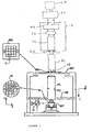
- Figure 1 schematically depicts a lithographic projection apparatus according to a particular embodiment of the invention.
- the apparatus comprises:
- the apparatus is of a transmissive type (i.e. has a transmissive mask). However, in general, it may also be of a reflective type, for example (with a reflective mask). Alternatively, the apparatus may employ another kind of patterning means, such as a programmable mirror array of a type as referred to above.
- the radiation system may comprise a source LA (e.g. a mercury lamp, a Krypton-Fluoride excimer laser or a plasma source) that produces a beam of radiation.
- a source LA e.g. a mercury lamp, a Krypton-Fluoride excimer laser or a plasma source
- This beam is fed into an illumination system (illuminator) IL, either directly or after having traversed conditioning means, such as a beam expander Ex, for example.
- the illuminator IL may comprise adjusting means AM for setting the outer and/or inner radial extent (commonly referred to as ⁇ -outer and ⁇ -inner, respectively) of the intensity distribution in the beam.
- it will generally comprise various other components, such as a condenser CO and an integrator IN.
- the condensor CO projects the incoming light to the integrator IN.
- the integrator IN may, for example, be formed of a quartz rod, and is used to improve the intensity distribution of the beam to be projected over the cross section of the beam.
- the integrator IN thus improves the illumination uniformity of the projection beam PB.
- the beam PB impinging on the mask MA has a desired uniformity and intensity distribution in its cross-section.
- the radiation system may further include a relay optics RL.
- the relay optics are preferably a sealed assembly mounted in the lithography apparatus and contains expansion optics, a mirror for directing the projection beam toward the mask, a further condensor lens and a projecting lens.
- the function of the relay optics RL is to image the masking device "image" plane on the reticle mask "focus” plane.
- the relay optics RL is optional. Its main functions are to image the blades of the masking device with a sufficiently small edge width, match the entrance pupil function of the projection lens, and provide a uniform illumination of the mask.
- the source LA may be within the housing of the lithographic projection, but that it may also be remote from the lithographic projection apparatus, the radiation beam which it produces being led into the apparatus (e.g. with the aid of suitable directing mirrors).
- the current invention and claims encompass both of these scenarios.
- the masking device MD is disposed between the illuminator IL and the relay optics RL. However, as shown in Figure 4, the masking device MD may instead be disposed directly above the mask MA.
- the masking device MD is a spatial filter. Those parts of the projection beam falling on the masking device will be preferably reflected or absorbed. Only those parts of the projection beam not falling on the masking device will be transmitted.
- the masking device projects a "slit" on to the mask. As discussed below, the masking device is controllable to control the dimensions of the slit through which the projection beam passes.
- the beam PB intercepts the mask MA which is held in a mask holder on a mask table MT. Having been transmitted through (or reflected by in the case of a reflective mask) the mask MA, the beam PB passes through the projection system PL, which focuses the beam PB onto a target portion C of the substrate W. With the aid of the second positioning means (and interferometric measuring means IF), the substrate table WT can be moved accurately, e.g. so as to position different target portions C in the path of the beam PB. Similarly, the first positioning means can be used to accurately position the mask MA with respect to the path of the beam PB, e.g.
- the object tables MT, WT will be realized with the aid of a long stroke module (coarse positioning) and a short stroke module (fine positioning), which are not explicitly depicted in Figure 1.
- the mask table MT may just be connected to a short stroke actuator, or may be fixed.
- the depicted apparatus can be used in two different modes:
- FIG. 2 shows a masking device according to an embodiment of the invention.
- the masking device MD comprises a first masking means and a second masking means.
- the masking means may be plates or blades or other constructions suitable for selectively obscuring the location at which the patterning means, when in use, is located.
- the masking device preferably comprises blades 4a, 4b, 6a, 6b, which preferably are arranged to form two sets of blades: the X-blades and the Y-blades.
- the two sets of blades are mechanically uncoupled with respect to one another. That is to say that the blades are mounted in such a manner that a vibration generated in either an X or Y blade is not transmitted to a Y or X blade, and vice versa.
- the mounting of the X and Y blades is described in more detail hereinafter.
- the blades may also be considered as being plates or other constructions suitable for obscuring.
- the Y blades 4a and 4b are driven, whilst the X-blades 6a and 6b are stationary during exposure.
- the invention is not limited in this respect and the Y-blades may be stationary, or the X-blades may be moveable while the Y-blades are stationary.
- the blades which move during scanning, hereinafter referred to the Y blades are controlled by software and electronics.
- the X-blades are similarly controlled with software and electronics.
- the Y-blades move together and apart in the Y-direction, the Y-direction also being the scanning direction, i.e. the direction in which the mask table and the substrate table are moved in a scanning exposure.
- the moving blades are controlled to move according to a desired scanning profile.
- the blades are arranged to block the light source, thus preventing the light source from impinging on the patterning means.
- the blades are controlled to move so that the light source impinges on the patterning means.
- the dimensions of the light source determine what is referred to as the scanning slit.
- the dimensions of the scanning slit are, in particular, determined by the optical source and the quartz rod.
- the scanning slit width in the Y-direction which is conventionally the scanning direction, is variable and will be chosen depending on factors such as the dimensions of the mask to be exposed.
- the blades are accelerated to the scanning width as quickly as possible. Typical accelerations of the blades are in excess of 10 m/s/s and up to the region of 45m/s/s.
- the Y-blade assembly is scanned at a predetermined scanning speed, typically in excess of 500mm/s, across the mask. Once the mask has been scanned, the blades are moved to be arranged so as to block the light source, and thus prevent the light source impinging on the patterning means.
- the blades may be moved in the scanning direction to block the slit.
- the trailing blade may be moved in the direction of the scan or the leading blade may be moved in the direction opposite to the scanning direction towards the trailing blade.
- the movements of the blades are not however limited to the example described above, and the blades of the present invention may be controlled to move according to any predetermined scanning profile. If desired, the blades may also be held stationary, either closed or at a constant slit width.
- the control means for the blades includes a driver 8 for generating high level commands, which are fed to a motion controller 7.
- the driver 8 is a software driver.
- the programmable motion controller 7 From the high level commands, the programmable motion controller 7 generates control signals which are fed to an amplifier 6 which generates a current in accordance with the control signals to drive motor windings 1.
- a position measurement device 3 which provides data concerning the position of the blades 4a,4b,6a,6b. This data is fed back via the amplifier 6 to the motion controller 7.
- each blade is provided with a motor 1,2 and a positioning measuring means 3.
- the motor 1,2 comprises at least one motor winding 1, which does not come into contact with the blade it drives, and a magnet 2.
- the magnet is mounted directly on an intermediate portion 19 around which the motor windings 1 are disposed.
- the intermediate portion 19 on which the magnet 2 is disposed resembles a "pan handle" of the blade support member for the X blades, and for the Y blades the magnet is integrated at the rear end of the blades, that is the end remote from the optical blade edge.
- the intermediate portion may be constructed out of the same material as the blade, however this is not essential. Also, it is not essential that the blade and the intermediate portion 19 be constructed from a single piece of material.
- the blades are supported by blade support members.
- the blade support members for the Y-blades comprise non-contact bearings.
- the motors 1,2 described above are preferably non-contact linear motors. These features reduce the moving mass of the blades and enhance durability. Further the use of non-contact bearings and motors reduce frictional forces, which in turn allows the blades to be subject to higher accelerations without causing disturbances to other components in the system. This also results in improved accuracy of the blade mobility, with the blades being able to be moved at higher speeds and accelerated at higher accelerations.
- the action of the driver 8 is translated to the blades via the intermediate portion 19.
- the motor coils are preferably provided on the blade support and are arranged to surround the intermediate portion 19, rather than on the blades as is conventional.
- This arrangement provides the benefit that there are no moving cables and hoses, because the heat generating coils are disposed on a fixed frame. Thus, a longer lifetime is achieved.
- This arrangement provides the additional benefit that no cables are required to be connected to the moving parts, there is no cross talk between motors driving the moving parts, and the lifetime of the apparatus is increased.
- magnet 2 is provided with the blade(s) which responds to the drive signal.
- blades constructed and driven according to the present invention can support scanning at the wafer stage at speeds up to 550 millimetres per second, and can further be subject to a blade acceleration of 45metres/second/second whilst maintaining a tracking error of less than 10 micrometres.
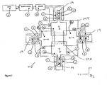
- FIG 2 is a plan view of the mask table MT (and mask MA) showing its location relative to an embodiment of the masking device.
- the mask table MT is itself movable by means of positioning means (not shown).
- the masking device may be provided on the mask table MT and so the masking device MD moves with the mask table MT because it is mechanically coupled to it.
- the masking device MD may be coupled electronically, magnetically or electrostatically to the mask table MT.
- the masking device is demountable.
- the masking device MD can be coupled to the long-stroke or short-stroke module of the positioning means PM rather than the mask table MT itself.
- two pairs of blades 4a,4b,6a,6b are used to provide selectivity in terms of the extent the mask MA (or the patterned beam) is obscured using the masking device MD and are moveable in the directions indicated by the arrows.
- the two blades 4a,4b are mounted perpendicularly to the blades 6a,6b via non-contact linear motors 1,2.
- the blades 4a,4b move together and apart in the Y-direction (Y-blades) and the blades 6a,6b move together and apart in the X-direction (X-blades).
- all four blades may be coupled via the motion controller 7 and the driver 8 to the motion controller and driver of the patterning means.
- the blades in general perform two types of movements.
- the first are movements to block or unblock one of the light source impinging on the patterning means or patterned beam. These movements include closing/opening movements in which the two blades of a pair move relative to one another so as to adjust the part of the mask or patterned beam which is obscured.
- the second are tracking movements in which both blades of a pair move by the same vector so as to keep track of movements of the mask table.
- the tracking movements are carried out automatically when the blades are coupled directly to the mask table.
- the X-blades are stationary.
- the X-blades are not limited in this respect. Motors are provided in order to move the X-blades with respect to one another.
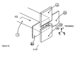
- Figure 3a shows a three dimensional overview of the masking device MD.
- the X-blades 6a,6b and Y-blades 4a,4b are disposed with respect to the integrator housing 9 (comprising, eg. integrator IN).
- the Y-blades 4a,4b are disposed downstream of the X-blades 6a,6b.
- the X-blades are constructed to withstand the thermal impact of the projection beam PB.
- the Y-blades 4a, 4b may be disposed upstream of the X-blades 6a,6b.
- Figure 3a enables the shapes of the slit forming blades to be seen.
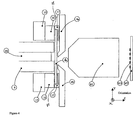
- Figure 3b shows a cross section in the YZ plane of part of the lithographic apparatus shown in Figure 1 showing the masking device MD according to an embodiment of the invention.
- the masking device of the present invention in particular features of the blades, and their arrangement with respect to each other and other components of the lithographic apparatus are described in further detail.
- the construction and arrangement of the two sets of blades results in a decoupling of the two sets of blades from one another and from mechanical coupling of the blades to the frame.
- the blades float on air bearings, rather than being mechanically coupled to the frame.
- the Y blades in particular, are not subject to disturbances from the X-blades or from the frame, such as vibrations.
- the X and Y blades are constructed to be arrangeable so that their position and mobility is not directly determined by the position and mobility of the other set of blades. Uncoupling the blades results in a minimization of the moveable mass. Whereas conventional movable blades weigh in excess of 600 grammes, blades according to the present invention weigh in the order of 100 grammes. This has been achieved by the use of inter alia a direct drive, where the magnets of the driving motor are integrated into the blade or blade support member, and the mechanical decoupling of the two sets of blades from each other.
- Figure 3b shows the integrator IN, which is preferably a quartz rod, mounted in integrator housing 9. Also shown is the masking device MD disposed downstream of the integrator IN in the direction of the projection beam PB. A portion of the relay optics RL is also shown disposed downstream of the masking device MD. The mask MA (not shown) to be exposed is disposed downstream of the relay optics in the direction of the projection beam PB.
- the masking device MD comprises two sets of blades 4, 6 arranged to selectively obscure part of the mask MA from the radiation beam.
- the Y blades 4 are movable together and apart in the Y-direction, which is also the direction of scanning of the mask.
- the X-blades 6 are not moved with respect to each other during a scan. Thus, the distance between the X-blades during a scan is constant. However, the X-blades 6 may be moved with respect to each other if required by the scan profile, as determined by the width of the image on the mask.
- the radiation system LA, Ex, IL generates a beam having a focal plane 10, corresponding to a plane substantially conjugate to the filed plane of the mask, at a predetermined location depending on the optical components of the radiation source, illuminator and relay optics.
- Figure 3b shows the focal plane at location 10, the focal plane may vary. In which case adaptation of the position of the blades in the Z-direction with respect to the focal plane may be necessary, preferably, using a Z manipulator as shown in Figure 8.
- the end of the quartz rod is disposed at one end of the margins of the focal plane in the Z-direction and the Y-blades are disposed at the opposite end of the margin in the Z-direction, it has been found that space is provided to dispose the X-blades in a mechanically decoupled manner from the Y-blades, whilst still allowing a sharply focused slit to be projected on to the patterning means.
- the blades are disposed within a certain distance of the focal plane 10 of the beam, which is preferably in the order of 50 micrometers.
- the stationary blades 6, also referred to as the X blade are preferably disposed at a distance less than 200 micrometres, and preferably within a distance 11 of approximately 100 micrometres from the movable blades 4.
- the focal plane 10 in the example shown lies between the stationary and the movable blades.
- the stationary blades are disposed a distance 12 from the end of the quartz rod plus tolerances 13.
- the distance 12 is less than 100 micrometres.
- the distance between the end of the quartz rod and the focal plane of the beam is shown by arrow 14, and is typically of the order of 300 to 600 micrometres.
- the stationary during scanning (or X) blades are of a thinner construction than the movable during scanning (or Y) blades and that the stationary blades are disposed in the beam upstream of the movable blades.
- This construction is discussed in more detail hereinbelow.
- the invention is not limited to the example given below. It is envisaged that the stationary during scanning blades may alternatively be thick and the moving during scanning blades may alternatively be thin.
- the masking device and in particular the blades, are subject to large thermal stress from the projection beam radiation.
- the thermal load on the blades is a reason why blades in conventional masking devices have a large thickness, of the order of 1 to 3 millimeters.
- cooling of conventional blades is limited.
- the energy of the radiation blocked by the masking device is a problem for masking devices because it can affect the apparatus components and the blades themselves.
- the blades may be provided with a surface which is reflective to the projection beam radiation.
- the blades are provided with an ultra violet reflecting coating. This alone however, may not be sufficient, and in addition, may not be permitted for all light source wavelengths envisaged to be used with the present invention.
- the stationary X-blades are asymmetrically cooled with respect to the moving blades, i.e. the amount of cooling applied to the stationary, or upstream, blades is different from that applied to the other set of blades, and preferably the amount of cooling is greater. It has further been found that by cooling the X-blades to a sufficient degree, the thickness of the X blades can be reduced.
- the X-blades are made sufficiently thin, so that there is enough space to allow the Y-blade to be downstream of the X-blade whilst still lying within the sufficiently small distance of the focal plane to allow a sufficiently sharp slit to be projected onto the patterning means.
- cooling ducts are provided in the blade support member.
- Such ducts allow conventional air hoses to be dispensed with.
- the ducts may have various configurations and may be used for supplying various coolants, such as air and/or water, in order to cool.
- ducts are provided in the blade support member. Coolant is fed from an inlet provided on the support member to an outlet via the ducts. The outlet preferably comprises an opening provided in the support member.
- the ducts are preferably disposed adjacent the blade to be cooled. The water is circulated via the ducts underneath the blades to an outlet also preferably provided on the frame. Cooling of the masking device MD is described in more detail with reference to Figures 6 and 7 below.
- blades shown in the figures may be made of, for example, a ceramic or diamond material.
- Preferred materials for the blades are chemical vapour deposition diamond (CVD diamond), aluminium, tungsten copper alloy and silicon carbide, all of which exhibit a good combination of the required properties. In particular, CVD diamond is preferred.
- the thickness of the X-blade is preferably in the order of approximately 0.4mm in the direction of the projection beam.
- the material of the X-and Y-blades has a high Young's modulus and low density, in order that the blades whilst being stiff are as light as possible, in order to reduce the moving mass of the blades.
- the Y-blade shown in the figures may be made of, for example, aluminium or an aluminium beryllium alloy (AlBe). Preferred materials for the Y-blades include metal matrix composites, ceramics, diamond, beryllium alloys and graphite.
- the thickness of the Y blades is in the order of 6mm.
- the blades can also be made of any appropriate material, which in general comprise materials that can withstand the radiation, are rigid and lightweight, or can be provided with coatings having these properties. Further, some materials, such as certain ceramics have the advantage that it can include one or more cooling channels in it, as described in European Application Number 00304336.1 (applicant's ref: P-0183) which is hereby incorporated herein by reference, to remove heat due to incident radiation.
- Figure 4 shows a cross-section of the masking device of Figure 2 in the Y-Z plane.
- Figure 4 shows the stacking of the X and Y blades.
- the X-blade 6 is shown in plane.
- the masking device MD is disposed above the mask.
- the X-blade 6 is mounted on a blade support member 15, on which a heat sink 16 is provided.
- a clamping device 17 is provided to clamp the X blade to the heat sink 16, so that good thermal contact between the X blade and the heat sink promotes cooling of the X blade.
- the masking means comprises a blade mounted on the blade support, wherein a layer 18 of material having a high thermal conductivity is disposed between said blade and said blade support.
- FIG. 5 shows the X blades 6 mounted on a first blade support member 15 which provides support to the blades.
- the support member 15 comprises a U-shaped member 22, wherein opposite edges 6c, 6d of each blade are supported by opposite arms of the U-shaped member.
- the support member 15 also includes portions 23 extending from the bottom of each corner of the U-shape.
- Cooling means 24a are provided in the support member 15.
- liquid for example, water
- cooling is provided by cooling ducts 24a, although, the ducts could also be used for gas cooling.
- ducts 24b may supply gas to the gas bearings of the X blades.
- the gas supplied by ducts 24b also contributes to cooling of the blades.
- the gas ducts 24b are disposed further from the blade than the water cooling ducts 24a.
- the gas and liquid ducts 24a, 24b are substantially parallel ducts disposed on opposite sides of support member 15 .
- the support member 15 may be provided with additional features which enable the masking device to exhibit an improved reaction to thermal stress, including thermal cycling.
- Support member 15 may be provided with movement limiting means 50 which minimize movement of the support member, such as flexing, bending etc, during thermal stress.
- the movement limiting means 50 comprise features 51, 52 formed in the support member 15. The features may take various forms and configurations.
- the features comprise slots 52 joined at hinges 51.
- the hinges 51 are formed by holes bored into the support member 15.
- the features provide the structure with a certain degree of flexibility. It has been shown that by arranging the movement limiting means in a particular way, the support member's reaction to thermal stress is moderated significantly.
- the dimensions and configurations of the features, such as the slots and wings will depend on factors such as the materials of the support member and the thermal stress characteristics.
- clamping means 60 is also provided on the support member 15 .
- the clamping means comprises one or more fingers which extend from the support member 15 to clamp the blade.
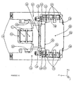
- Figure 6 shows further embodiments of the X-blades mounted on a first support member 15.
- opposite edges 6c, 6d of the X-blade 6 are mounted on opposite arms of the U-shaped support member 15.
- the motor magnets 2 are mounted on a magnet support member 23.
- the magnet support member 23 comprises a portion disposed between the opposite arms of the U-shaped support member 15.
- the two magnets 2 are shown, which are part of the motor (not shown in its entirety) which drives the blades.
- Also provided on support member 15 is a cooling structure 16, 19, 24.
- the cooling structure 16, 19, 24 comprises portions 16 mounted on each arm of the support member 15, inlet 19 through which coolants may be introduced into the coolant structure 16, 19, 24.
- the structure is provided with coolant ducts 24 (shown in dotted lines) extending through the coolant structure, preferably along the length of the coolant structure. Also provided is a connecting conduit for connecting the coolant ducts in each cooling portion 16 mounted on each arm of the support member 15.
- One of the cooling inlets 19 may also function as a cooling outlet 19 to allow the circulated coolant to leave the structure 16, 24.
- the cooling means may provide cooling by various fluid coolants, both gases and liquids.
- a preferred coolant is water.
- the portions of the cooling structure are provided on the supporting member 15 to preferably align with the opposing edges 6c, 6d of the X-blade, respectively.
- the X-blade is supported directly by the cooling structures 16.
- the invention is not limited in this respect, and the X-blades may be supported by the frame of the support member.
- a clamping device 17 comprises a plurality of resilient means arranged in use to attach to a surface of the X-blade along the edge 6c, 6d of the X-blade in the X direction.
- the resilient means comprise an L shaped spring which exerts a force downwards through the blade in the Z-direction.
- Clamping means 20, 21 comprises a stop 20 and a resilient means 21 disposed at opposite edges 6e, 6f of the X-blade in the X-direction, wherein resilient means 21 is arranged to exert a force on the X-blade in the X-direction towards stop 20.
- the resilient means 21 may comprise a spring and the stop 20 may comprise a fixed anvil.
- resilient means 21 is configured from a flat portion material. An L-shaped cut is provided in the flat piece of material to provide resiliency. It will be appreciated that the resiliency of the clamping means can be determined according to the choice of material and the dimensions of the cut in the portion.
- the X-blade is clamped with clamping devices 17 on both sides of its support member 15, as discussed above.
- Clamping device 17 clamps the upper surface of the X-blade.
- This arrangement provides the advantage that thermal expansion of the clamping and clamped components is compensated equally in the X-direction, whilst keeping the blade securely clamped, and hence accurately aligned.
- a layer of silver foil is disposed between the blade and the cooling body. The silver layer has good thermal conductivity. This arrangement provides a further particular advantage of reducing the hot spot temperature whilst maintaining good thermal contact between the blade and the cooling body.
- the hot spot is defined as being the center of the blade, and is located in the vicinity of reference number 6.
- blade dampers 18 disposed on the respective ends of opposite arms of the support member 15, which are in the form of buffers, which function to lessen or absorb the shock of any disturbance exerted on the support member 15.
- the support member 15 is also provided with gas bearings (not shown) on the rear side of the support member.
- gas bearing preload strips 22 which are used to preload the gas bearing provided on the support member 15.
- the gas bearing preload strips 22 are preferably made of a metal, such as iron.
- magnets which can form part of the gas bearings. The magnets are arranged in the housing so as to exert a force on the preload strips 22.
- the gas bearing exerts an opposite force to that exerted by the magnets.
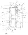
- Figure 7 provides a plan view of a second support member 70 for the Y-blades 4a, 4b showing in particular a gas bearing which is in use supports the Y-blades and the cooling structures.
- Y-blades 4a and 4b are shown in dotted outline disposed in a recess 79 formed in the second support member 70.
- Also shown in the centre of the recess 79 is an outline of a through hole 82 formed in the support member 70 through which the projection beam passes (and over which the Y-blades move in part).
- Also shown in Figure 7 is detail of the gas bearing which supports the Y-blades.
- a gas inlet 71 is provided in the support member 70. Gas is introduced through the inlet 71 and passes through duct 80 formed in the support member 70.
- a slightly raised portion 74 is formed on the floor of the recess 79.
- the duct 80 is connected to openings 75 formed in the raised portion 74.
- the Y blade disposed in recess 79 is supported by the gas leaving openings 75.
- the Y-blade is uncoupled from the support member 70.
- a plurality of gas bearings may be provided.
- the Y-blades are mechanically isolated, in use, from the machine.
- the scanning Y blades require cooling.
- the blades are guided with gas bearings as described above.
- the second supporting member 70 comprises a gas bearing surface 76.
- the gas bearing surface is stationary and is fluid cooled by a cooling system 72, 73, 81.
- the Y-blades are also cooled by the cooling system 72, 73, 81.
- Fluid coolant preferably water, is introduced through inlet 72 formed in support member 70.
- the fluid is fed to outlet 73 formed in the support member 70 via a duct 81.
- the duct is preferably configured in the support member 70 to transverse the width of the Y-blade when disposed in said recess.
- the gas bearing causes the Y-blade to be raised above the floor of the support structure by approximately 10-20 micrometers.
- the X-blades are controlled to act as a heat shield in the case of the Y-blades becoming overheated.
- the X-blades are controlled to move to block the light impinging on the Y-blades.
- the controller will cause the X-blades to move into a position which shades the Y-blades from the optical source.
- the X-blades function as a thermal shield to protect the Y-blades.
- the X-blades are constructed to be robust with respect to the projection beam, being able to withstand the full impact of the projection beam without suffering adverse effects.
- the first and second masking means are arranged in the apparatus, mechanically uncoupled with respect to each other.
- the first and second support members are mechanically uncoupled.
- the X-blade and Y-blade assemblies are modular units.
- the X-blade assembly and the Y-blade assembly are two separate modules that are assembled and tested independently from one another.
- the complete modules are assembled with respect to one another as shown in Figures 2-4 and 8 for use. To do this certain parts of the X-blade assembly and Y-blade assembly are coupled to each other. However, it is not necessary to couple the X blades with respect to the Y blades.
- the masking assembly is easier to assemble and test than conventional assemblies.
- separate components can be assembled and tested without having to disassemble the entire assembly. This saves time and man hours.
- At least one of the blades is provided with an electrostatic discharge rod which conducts electrostatic charge towards it, and thus away from sensitive sensors and electronics.
- the rod may be disposed on either the X or the Y or both blades.
- the rod is disposed on the Y blades.
- it comprises a thin tapered rod mounted on one of the blades. Its dimensions and material are chosen to provide optimum electrostatic conduction whilst having a minimum mass.
- the rod may, by way of example, be made of copper.
- the motors for driving the blades are controlled by software which comprises a list of instructions to control the motors.
- software which comprises a list of instructions to control the motors.
- sensors are provided which detect the position of the blades and provide feedback to the control means.
- the software which provides the instructions to the motors is adapted to take account of the sensed position data, and is designed to preclude the possibility that the blades come into contact with each other. In this way, the control software which drives the motors prevents collision of the moving X or Y blades, and further collision between an X and a Y blade.
- Figure 8 shows an embodiment of the present invention detailing features which overcome this problem.
- Figure 8 shows a manipulator screw 25 for manipulating the position of the X and Y blades in the Z-direction, that is in the direction of the optical axis.
- a frame 27 is provided within the X and Y assemblies as shown in Figures 6 and 7, respectively, are mounted.
- the X and Y assemblies are denoted by reference numeral 28 in Figure 8, and are supported by frame 27.
- the projection beam projects through opening 31 in the Z direction. It is seen that the Z-manipulator screw 25, when turned, exerts a force on a base plate 26, which is provided with manipulator hinges.
- the frame 27 supporting the X and Y (sub) assemblies remains fixed on its own supporting frame.
- the Z-direction manipulator 25 is integrated in the frame 27.
- the Z manipulator is an adjusting means that comprises a screw 25 which acts on a resilient member, which in turn exerts force in the Z-direction on the X- and Y- assemblies 28.
- a Z manipulator locking screw 29 and a further Z manipulator locking device 30, which maintain the X- and Y- assemblies in the desired location in the Z direction once the desired position has been achieved.
- a sensor is provided in the vicinity of the downstream end of the quartz rod to sense if the blade comes within a predetermined distance of the exit surface of the quartz rod. If the sensor detects that the blade is within the predetermined distance of the exit surface, the detected signal may be used by an operator to control the Z manipulator to move the blade away from the exit surface in the Z direction. This arrangement improves the reliability of the apparatus, and reduces the risk of damaging the integrator IN.
Landscapes
- Physics & Mathematics (AREA)
- General Physics & Mathematics (AREA)
- Health & Medical Sciences (AREA)
- Life Sciences & Earth Sciences (AREA)
- Atmospheric Sciences (AREA)
- Toxicology (AREA)
- Engineering & Computer Science (AREA)
- Environmental & Geological Engineering (AREA)
- Epidemiology (AREA)
- Public Health (AREA)
- Exposure And Positioning Against Photoresist Photosensitive Materials (AREA)
- Exposure Of Semiconductors, Excluding Electron Or Ion Beam Exposure (AREA)
Priority Applications (1)
| Application Number | Priority Date | Filing Date | Title |
|---|---|---|---|
| EP04076581A EP1491960B1 (de) | 2003-05-30 | 2004-05-28 | Lithographischer Apparat |
Applications Claiming Priority (3)
| Application Number | Priority Date | Filing Date | Title |
|---|---|---|---|
| EP03076673A EP1482363A1 (de) | 2003-05-30 | 2003-05-30 | Lithographischer Apparat |
| EP03076673 | 2003-05-30 | ||
| EP04076581A EP1491960B1 (de) | 2003-05-30 | 2004-05-28 | Lithographischer Apparat |
Publications (3)
| Publication Number | Publication Date |
|---|---|
| EP1491960A2 true EP1491960A2 (de) | 2004-12-29 |
| EP1491960A3 EP1491960A3 (de) | 2005-01-19 |
| EP1491960B1 EP1491960B1 (de) | 2012-04-25 |
Family
ID=33420576
Family Applications (1)
| Application Number | Title | Priority Date | Filing Date |
|---|---|---|---|
| EP04076581A Expired - Lifetime EP1491960B1 (de) | 2003-05-30 | 2004-05-28 | Lithographischer Apparat |
Country Status (1)
| Country | Link |
|---|---|
| EP (1) | EP1491960B1 (de) |
Cited By (7)
| Publication number | Priority date | Publication date | Assignee | Title |
|---|---|---|---|---|
| US7403265B2 (en) | 2005-03-30 | 2008-07-22 | Asml Netherlands B.V. | Lithographic apparatus and device manufacturing method utilizing data filtering |
| US7548303B2 (en) | 2004-09-04 | 2009-06-16 | Nikon Corporation | Cooling assembly for a stage |
| US8049865B2 (en) | 2006-09-18 | 2011-11-01 | Asml Netherlands B.V. | Lithographic system, device manufacturing method, and mask optimization method |
| TWI681260B (zh) * | 2016-05-31 | 2020-01-01 | 上海微電子裝備(集團)股份有限公司 | 光刻機刀口組、大視場光刻機和曝光方法 |
| WO2020207656A1 (en) * | 2019-04-09 | 2020-10-15 | Kulicke & Soffa Liteq B.V. | Lithographic systems and methods of operating the same |
| WO2024056318A1 (en) * | 2022-09-15 | 2024-03-21 | Asml Netherlands B.V. | Illumination adjustment apparatuses and lithographic apparatuses |
| EP4488755A1 (de) * | 2023-05-25 | 2025-01-08 | Canon Kabushiki Kaisha | Struktur, belichtungsvorrichtung und artikelherstellungsverfahren |
Family Cites Families (8)
| Publication number | Priority date | Publication date | Assignee | Title |
|---|---|---|---|---|
| JPS6045252A (ja) * | 1983-08-23 | 1985-03-11 | Canon Inc | 投影露光装置の照明系 |
| DE68922945T2 (de) * | 1988-09-09 | 1995-11-16 | Canon K.K., Tokio/Tokyo | Belichtungsvorrichtung. |
| JP3291408B2 (ja) * | 1994-04-04 | 2002-06-10 | キヤノン株式会社 | 露光装置および集積回路の製造方法 |
| JP3506158B2 (ja) * | 1995-04-14 | 2004-03-15 | 株式会社ニコン | 露光装置及び走査型露光装置、並びに走査露光方法 |
| US5724122A (en) * | 1995-05-24 | 1998-03-03 | Svg Lithography Systems, Inc. | Illumination system having spatially separate vertical and horizontal image planes for use in photolithography |
| JP3416373B2 (ja) * | 1996-02-20 | 2003-06-16 | キヤノン株式会社 | 反射型x線マスク構造体、x線露光装置、x線露光方法ならびに該反射型x線マスク構造体を用いて作製されるデバイス |
| JP3387809B2 (ja) * | 1998-02-18 | 2003-03-17 | キヤノン株式会社 | 露光装置及びデバイス製造方法 |
| US6307619B1 (en) * | 2000-03-23 | 2001-10-23 | Silicon Valley Group, Inc. | Scanning framing blade apparatus |
-
2004
- 2004-05-28 EP EP04076581A patent/EP1491960B1/de not_active Expired - Lifetime
Non-Patent Citations (1)
| Title |
|---|
| None |
Cited By (14)
| Publication number | Priority date | Publication date | Assignee | Title |
|---|---|---|---|---|
| US7548303B2 (en) | 2004-09-04 | 2009-06-16 | Nikon Corporation | Cooling assembly for a stage |
| US7403265B2 (en) | 2005-03-30 | 2008-07-22 | Asml Netherlands B.V. | Lithographic apparatus and device manufacturing method utilizing data filtering |
| US7864295B2 (en) | 2005-03-30 | 2011-01-04 | Asml Netherlands B.V. | Lithographic apparatus and device manufacturing method utilizing data filtering |
| US8508715B2 (en) | 2005-03-30 | 2013-08-13 | Asml Netherlands B.V. | Lithographic apparatus and device manufacturing method utilizing data filtering |
| US9846368B2 (en) | 2005-03-30 | 2017-12-19 | Asml Netherlands B.V. | Lithographic apparatus and device manufacturing method utilizing data filtering |
| US8049865B2 (en) | 2006-09-18 | 2011-11-01 | Asml Netherlands B.V. | Lithographic system, device manufacturing method, and mask optimization method |
| TWI681260B (zh) * | 2016-05-31 | 2020-01-01 | 上海微電子裝備(集團)股份有限公司 | 光刻機刀口組、大視場光刻機和曝光方法 |
| WO2020207656A1 (en) * | 2019-04-09 | 2020-10-15 | Kulicke & Soffa Liteq B.V. | Lithographic systems and methods of operating the same |
| CN113767335A (zh) * | 2019-04-09 | 2021-12-07 | 库力&索法利特克有限公司 | 平版印刷系统及操作该系统的方法 |
| US11550232B2 (en) | 2019-04-09 | 2023-01-10 | Kulicke & Soffa Liteq B.V. | Lithographic systems and methods of operating the same |
| US11921435B2 (en) | 2019-04-09 | 2024-03-05 | Kulicke & Soffa Liteq B.V. | Lithographic systems and methods of operating the same |
| US11947271B2 (en) | 2019-04-09 | 2024-04-02 | Kulicke & Soffa Liteq B.V. | Lithographic systems and methods of operating the same |
| WO2024056318A1 (en) * | 2022-09-15 | 2024-03-21 | Asml Netherlands B.V. | Illumination adjustment apparatuses and lithographic apparatuses |
| EP4488755A1 (de) * | 2023-05-25 | 2025-01-08 | Canon Kabushiki Kaisha | Struktur, belichtungsvorrichtung und artikelherstellungsverfahren |
Also Published As
| Publication number | Publication date |
|---|---|
| EP1491960A3 (de) | 2005-01-19 |
| EP1491960B1 (de) | 2012-04-25 |
Similar Documents
| Publication | Publication Date | Title |
|---|---|---|
| US8059261B2 (en) | Masking device, lithographic apparatus, and device manufacturing method | |
| US7126666B2 (en) | Lithographic apparatus, device manufacturing method and device manufactured thereby | |
| KR100588119B1 (ko) | 리소그래피장치 및 디바이스제조방법 | |
| KR100938913B1 (ko) | 인코더 타입 위치 센서 시스템을 갖는 리소그래피 장치 | |
| JP2002198284A (ja) | ステージ装置および露光装置 | |
| US7167234B2 (en) | Actuator assembly and lithographic apparatus comprising such an actuator assembly | |
| NL2017808A (en) | Positioning device, lithographic apparatus and device manufacturing method | |
| US7088428B2 (en) | Lithographic actuator mechanism, lithographic apparatus, and device manufacturing method | |
| EP1491960B1 (de) | Lithographischer Apparat | |
| US7372549B2 (en) | Lithographic apparatus and device manufacturing method | |
| US20090268190A1 (en) | Lithographic apparatus and device manufacturing method | |
| US7492440B2 (en) | Lithographic apparatus and device manufacturing method | |
| JP4970846B2 (ja) | リソグラフィ装置及びデバイス製造方法 | |
| US7180571B2 (en) | Lithographic projection apparatus and actuator | |
| US8836913B2 (en) | Lithographic apparatus having an encoder type position sensor system | |
| JP2010268604A (ja) | モータ装置及びステージ装置並びに露光装置 | |
| US7692768B2 (en) | Iron core motor driven automatic reticle blind | |
| EP1465014B1 (de) | Lithographischer Apparat, Verfahren zur Herstellung eines Artikels und damit erzeugter Artikel | |
| JP2003299339A (ja) | リニアモータおよびステージ装置並びに露光装置 |
Legal Events
| Date | Code | Title | Description |
|---|---|---|---|
| PUAI | Public reference made under article 153(3) epc to a published international application that has entered the european phase |
Free format text: ORIGINAL CODE: 0009012 |
|
| PUAL | Search report despatched |
Free format text: ORIGINAL CODE: 0009013 |
|
| AK | Designated contracting states |
Kind code of ref document: A2 Designated state(s): AT BE BG CH CY CZ DE DK EE ES FI FR GB GR HU IE IT LI LU MC NL PL PT RO SE SI SK TR |
|
| AX | Request for extension of the european patent |
Extension state: AL HR LT LV MK |
|
| AK | Designated contracting states |
Kind code of ref document: A3 Designated state(s): AT BE BG CH CY CZ DE DK EE ES FI FR GB GR HU IE IT LI LU MC NL PL PT RO SE SI SK TR |
|
| AX | Request for extension of the european patent |
Extension state: AL HR LT LV MK |
|
| 17P | Request for examination filed |
Effective date: 20050421 |
|
| AKX | Designation fees paid |
Designated state(s): DE FR GB IT NL |
|
| GRAP | Despatch of communication of intention to grant a patent |
Free format text: ORIGINAL CODE: EPIDOSNIGR1 |
|
| RIN1 | Information on inventor provided before grant (corrected) |
Inventor name: VERDOES, GERARDUS JOHANNES Inventor name: VERVOORDELDONK, MICHAEL JOHANNES Inventor name: VAN DEN HOVEN, GERBRAND PETRUS JOHANNES Inventor name: MOLENAAR, JACOBUS FREDERIK Inventor name: VERWEIJ, ANTOINE HENDRIK Inventor name: VAN EIJK, JAN Inventor name: PARDOEL, MICHEL GERARDUS |
|
| GRAS | Grant fee paid |
Free format text: ORIGINAL CODE: EPIDOSNIGR3 |
|
| GRAA | (expected) grant |
Free format text: ORIGINAL CODE: 0009210 |
|
| AK | Designated contracting states |
Kind code of ref document: B1 Designated state(s): DE FR GB IT NL |
|
| REG | Reference to a national code |
Ref country code: GB Ref legal event code: FG4D |
|
| REG | Reference to a national code |
Ref country code: DE Ref legal event code: R096 Ref document number: 602004037505 Country of ref document: DE Effective date: 20120621 |
|
| REG | Reference to a national code |
Ref country code: NL Ref legal event code: VDEP Effective date: 20120425 |
|
| PG25 | Lapsed in a contracting state [announced via postgrant information from national office to epo] |
Ref country code: NL Free format text: LAPSE BECAUSE OF FAILURE TO SUBMIT A TRANSLATION OF THE DESCRIPTION OR TO PAY THE FEE WITHIN THE PRESCRIBED TIME-LIMIT Effective date: 20120425 |
|
| PG25 | Lapsed in a contracting state [announced via postgrant information from national office to epo] |
Ref country code: IT Free format text: LAPSE BECAUSE OF FAILURE TO SUBMIT A TRANSLATION OF THE DESCRIPTION OR TO PAY THE FEE WITHIN THE PRESCRIBED TIME-LIMIT Effective date: 20120425 |
|
| PLBE | No opposition filed within time limit |
Free format text: ORIGINAL CODE: 0009261 |
|
| STAA | Information on the status of an ep patent application or granted ep patent |
Free format text: STATUS: NO OPPOSITION FILED WITHIN TIME LIMIT |
|
| GBPC | Gb: european patent ceased through non-payment of renewal fee |
Effective date: 20120725 |
|
| 26N | No opposition filed |
Effective date: 20130128 |
|
| PG25 | Lapsed in a contracting state [announced via postgrant information from national office to epo] |
Ref country code: GB Free format text: LAPSE BECAUSE OF NON-PAYMENT OF DUE FEES Effective date: 20120725 |
|
| REG | Reference to a national code |
Ref country code: DE Ref legal event code: R097 Ref document number: 602004037505 Country of ref document: DE Effective date: 20130128 |
|
| REG | Reference to a national code |
Ref country code: FR Ref legal event code: PLFP Year of fee payment: 13 |
|
| REG | Reference to a national code |
Ref country code: FR Ref legal event code: PLFP Year of fee payment: 14 |
|
| REG | Reference to a national code |
Ref country code: FR Ref legal event code: PLFP Year of fee payment: 15 |
|
| PGFP | Annual fee paid to national office [announced via postgrant information from national office to epo] |
Ref country code: DE Payment date: 20190521 Year of fee payment: 16 |
|
| PGFP | Annual fee paid to national office [announced via postgrant information from national office to epo] |
Ref country code: FR Payment date: 20190522 Year of fee payment: 16 |
|
| REG | Reference to a national code |
Ref country code: DE Ref legal event code: R119 Ref document number: 602004037505 Country of ref document: DE |
|
| PG25 | Lapsed in a contracting state [announced via postgrant information from national office to epo] |
Ref country code: FR Free format text: LAPSE BECAUSE OF NON-PAYMENT OF DUE FEES Effective date: 20200531 |
|
| PG25 | Lapsed in a contracting state [announced via postgrant information from national office to epo] |
Ref country code: DE Free format text: LAPSE BECAUSE OF NON-PAYMENT OF DUE FEES Effective date: 20201201 |