EP1492050B1 - Procédé et dispositif pour le traitement d'images et appareil de radiographie - Google Patents
Procédé et dispositif pour le traitement d'images et appareil de radiographie Download PDFInfo
- Publication number
- EP1492050B1 EP1492050B1 EP04013490A EP04013490A EP1492050B1 EP 1492050 B1 EP1492050 B1 EP 1492050B1 EP 04013490 A EP04013490 A EP 04013490A EP 04013490 A EP04013490 A EP 04013490A EP 1492050 B1 EP1492050 B1 EP 1492050B1
- Authority
- EP
- European Patent Office
- Prior art keywords
- image
- resolution
- ray
- spatial filter
- pixel
- Prior art date
- Legal status (The legal status is an assumption and is not a legal conclusion. Google has not performed a legal analysis and makes no representation as to the accuracy of the status listed.)
- Expired - Lifetime
Links
Images





Classifications
-
- G—PHYSICS
- G06—COMPUTING OR CALCULATING; COUNTING
- G06T—IMAGE DATA PROCESSING OR GENERATION, IN GENERAL
- G06T5/00—Image enhancement or restoration
- G06T5/73—Deblurring; Sharpening
-
- A—HUMAN NECESSITIES
- A61—MEDICAL OR VETERINARY SCIENCE; HYGIENE
- A61B—DIAGNOSIS; SURGERY; IDENTIFICATION
- A61B6/00—Apparatus or devices for radiation diagnosis; Apparatus or devices for radiation diagnosis combined with radiation therapy equipment
-
- G—PHYSICS
- G06—COMPUTING OR CALCULATING; COUNTING
- G06T—IMAGE DATA PROCESSING OR GENERATION, IN GENERAL
- G06T5/00—Image enhancement or restoration
- G06T5/20—Image enhancement or restoration using local operators
-
- G—PHYSICS
- G06—COMPUTING OR CALCULATING; COUNTING
- G06T—IMAGE DATA PROCESSING OR GENERATION, IN GENERAL
- G06T2207/00—Indexing scheme for image analysis or image enhancement
- G06T2207/10—Image acquisition modality
- G06T2207/10116—X-ray image
Definitions
- the present invention relates to an image processing method and apparatus and an X-ray imaging apparatus which are suitable for digital X-ray images and, more particularly, to sharpening processing for digital X-ray images.
- a film/screen system having a film and intensifying screen inserted in a cassette has been conventionally used as an X-ray sensor which acquires an X-ray image of a subject to be examined.
- an X-ray sensor which can directly convert an X-ray image into a digital output in real time.
- an X-ray detector formed by stacking a solid-state photodetector and a phosphor on a substrate made of quartz glass with an amorphous semiconductor being sandwiched between them.
- the solid-state photodetector is formed by arranging solid-state photodetecting elements, each comprised of a transparent conductive film and conductive film, in the form of a matrix.
- the phosphor converts X-rays into visible light.
- X-ray detectors which are designed to directly acquire X-rays through a solid-state photodetector without using any phosphor.
- X-ray detectors designed to acquire a digital X-ray image by irradiating a storage phosphor, which is a special phosphor, with an X-ray signal, causing optically stimulated luminescence using a laser, and detecting optically stimulated luminescence light through each photodetecting element.
- Phosphor plates using phosphors which are used in X-ray detectors include a phosphor plate formed by using a powder phosphor and a phosphor plate formed by crystal-growing a phosphor into a needle shape.
- a phosphor plate formed by using a powder phosphor increases in thickness (mass thickness or the like)
- the X-ray absorption efficiency increases, but the resolution deteriorates.
- a phosphor is crystallized into a needle shape, light emitted inside the phosphor is transmitted to the solid-state detector through a needle-like crystal serving like an optical fiber. Even if therefore, the phosphor increases in thickness, the resolution deteriorates less. Therefore, a phosphor plate formed by crystal-growing a phosphor into a needle shape is characterized in that it has high X-ray absorption efficiency and high resolution.
- a large-area phosphor plate without performance unevenness can be formed at low cost.
- a phosphor plate is to be formed by crystal-growing a phosphor into a needle shape, the phosphor must be grown into a needle shape by vacuum evaporation. It is difficult in terms of manufacturing techniques to form a large-area phosphor plate without performance unevenness at low cost.
- the presence of performance unevenness in an X-ray detector will adversely affect image quality.
- One of such performance unevenness is a resolution distribution in which different resolutions appear at different positions on the phosphor plate. This resolution distribution leads to different sharpnesses of image quality on the central portion and periphery, and hence is undesirable in terms of X-ray image diagnosis.
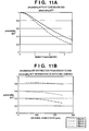
- Figs. 11A and 11B are views for explaining the resolution distribution of the above X-ray detector, and more specifically, graphs showing presampling MTFs indicating the resolutions of the X-ray detector.
- presampling MTF Modulation Transfer Function
- Fig. 11A shows the resolutions near the center and end portion of the X-ray detector.
- the abscissa represents the spatial frequency (unit: lp/mm: the abscissa representing the number of pairs of white and black lines existing within 1 mm); and the ordinate, the presampling MTF.
- the solid curve represents the resolution near the center of the X-ray detector.
- the broken curve represents the resolution near an end portion of the X-ray detector.
- the resolution distribution of the X-ray detector shown in Fig. 11A indicates that the resolution at the center is superior to the resolution at the end portion in each spatial frequency band.
- Fig. 11B shows the distribution of resolutions from near the center of the X-ray detector to near the end portion.
- the abscissa represents the distance from the center of the X-ray detector (if the X-ray detection surface of the X-ray detector is rectangular, the center indicates the intersection of diagonals of the rectangle); and the ordinate, the presampling MTF.
- Each data sequence indicates the values of presampling MTFs at spatial frequencies at intervals of 1.0 lp/mm.
- the presampling MTF gradually changes from near the center, and the presampling MTF near the center is superior to that at the end portion throughout all the spatial frequencies.
- the resolution of the X-ray detector changes from the center of the X-ray detector concentrically in accordance with changes in radius.
- a phosphor When a phosphor plate is to be formed by crystal growth, a phosphor must be crystal-grown by vacuum evaporation. The uniformity of a performance distribution greatly depends on the size of an evaporation furnace. As the size of an evaporation furnace increases, the price of a phosphor increases. In practice, therefore, it is difficult to form a large-area phosphor plate without performance unevenness.
- G. Brix et al. "Use of scanner characteristics in iterative image reconstruction for high-resolution positron emission tomography studies of small animals", European Journal of Nuclear Medicine, Berlin, Germany, vol. 24, no. 7, July 1997, pages 779-786 , XP002318420, ISSN: 0340-6997 discloses an improvement of the spatial resolution of a whole-body positron emission tomography (PET) system by incorporation of scanner characteristics into the process of iterative image reconstruction.
- PET positron emission tomography
- a transaxial resolution of the PET system operating in the 2D mode is characterized by a spatially variant two-dimensional line-spread function LSF(x,x',y,y') which describes the measured activity at a point (x, y) caused by a line-source positioned at a point (x',y') orientated parallel to the symmetry axis of the PET system.
- LSF line-spread function
- a reconstructed PET image is determined using this function.
- a one-dimensional line-spread function LSF ⁇ (s,s') describing the resolution of the circular PET system in radial direction at a distance s' from the centre can be used to blur a forward projection of the estimated image vector in each iteration step.
- J. A. Seibert et al.: "X-ray scatter removal by deconvolution", Medical Physics USA, vol. 15, no. 4, July 1988, pages 567-575 , XP002340970, ISSN: 0094-2405 discloses a retrospective scatter removal method based on a measurement of a point spread function (PSF).
- PSF point spread function
- the distribution of scattered x rays detected in a two-dimensional projection radiograph is measured.
- a scatter PSF is modeled.
- Analytical methods are used to convert the PSF into the frequency domain. Numerical inversion provides an inverse filter that operates on frequency transformed, scatter degraded images.
- the present invention has been made in consideration of the above problems, and has as its object to effectively improve the image quality of an image obtained from an image sensor having a resolution distribution.
- Fig. 1 is a schematic view showing a preferred example of the X-ray imaging apparatus according to the first embodiment.
- reference numeral 100 denotes an OPU (operation unit); 103, an X-ray source; 105, a subject to be imaged; 110, an X-ray detector; 115, an image processing unit; and 120, an image output unit.
- OPU operation unit
- 103 an X-ray source
- 105 a subject to be imaged
- 110 an X-ray detector
- 115 an image processing unit
- 120 an image output unit.
- an operator inputs X-ray imaging region information by using the OPU 100.
- the X-ray imaging region information includes a region of the subject which is to be imaged, X-ray imaging conditions, and the like.
- the X-ray detector 110 is ready for imaging.
- the technician checks the imaging ready state of the X-ray detector 110 and gives an instruction to start imaging
- the X-ray source 103 emits X-rays.
- the emitted X-rays are transmitted through the subject 105 and incident on the X-ray detector 110.
- the incident X-rays are detected by the X-ray detector 110.
- an X-ray image of the subject 105 is acquired as a digital X-ray image.
- the acquired digital X-ray image is subjected to the processing of correcting pixel variations of the X-ray detector 110 by the image processing unit 115, the processing of adjusting the dynamic range of the digital X-ray image, sharpening processing for the digital X-ray image, gradation processing, and the like.
- the image output unit 120 is preferably comprised of a monitor which displays a digital X-ray image, a printer which outputs a digital X-ray image onto a film or the like, a storage server which stores a digital X-ray image, and the like.
- the digital X-ray image processed by the image processing unit 115 is sent to the image output unit 120 to be displayed on the monitor. If necessary, the digital X-ray image is output from the printer onto a film to be used for diagnosis on the subject.
- the digital X-ray image is stored in the storage server or the like for the next diagnosis or the like.
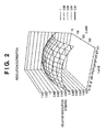
- Fig. 2 is a view showing resolution distribution data as an index indicating the resolution distribution of the X-ray detector 110.
- Resolution distribution data is an index indicating a resolution at a given position (represented by X- and Y-coordinates in Fig. 2 ) on the X-ray detector 110. Any data can be used as long as a resolution at a given position can be known from the numerical value of resolution distribution data at the given position.
- resolution distribution data can be generated by using presampling MTFs corresponding to resolutions at a plurality of positions on the X-ray detection surface of the X-ray detector 110.
- resolution distribution data like that shown in Fig. 2 can be generated by expressing a position on the X-ray detection surface of the X-ray detector 110 by X- and Y-axes, and substituting a presampling MTF value at a spatial frequency of 3.0 lp/mm for a resolution at the position.
- the process of performing sharpening processing by using resolution distribution data will be described below.
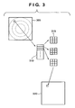
- Fig. 3 is a view for explaining sharpening processing in the first embodiment which improves the resolution distribution shown in Fig. 2 or 11B .
- reference numeral 305 denotes resolution distribution data; 310, a spatial filter table; 315, a spatial filter; and 320, an original image.
- the resolution distribution data 305 is data representing the relationship between a pixel position on the image and an index of resolution.
- the resolution of the X-ray detector 110 changes concentrically.
- an index of resolution may be an index that continuously changes like the presampling MTF shown in Fig. 11B , or discrete indexes defined by concentric regions like those shown in Fig. 3 .
- a pixel position on the resolution distribution data 305 is determined, and an index of resolution corresponding to the pixel position is determined.
- the spatial filter 315 is then selected from the spatial filter table 310 on the basis of the determined index of resolution.
- spatial filters are associated with indexes of resolution such that a spatial filter with a low enhancement degree is selected as the spatial filter 315 at a pixel position where the resolution is high on the X-ray image, and a spatial filter with a high enhancement degree is as the spatial filter 315 at a pixel position where the resolution is low.
- Fig. 4 is a view for explaining sharpening processing according to the second embodiment, which improves the resolution distribution shown in Fig. 2 or 11B .
- a spatial filter is selected in accordance with a resolution distribution as an index.
- a spatial filter is selected in accordance with a resolution distribution and X-ray dose as indexes. Adopting an X-ray dose as an index prevents a deterioration in image quality due to excessive enhancement of X-ray quantum noise.
- reference numeral 405 denotes resolution distribution data; 407, dose index data; 410, a spatial filter table; 415, a spatial filter; and 420, an original image.
- the reason why an X-ray dose is used as an index is that as the X-ray dose increases, quantum noise due to X-rays or system noise becomes less conspicuous on an image. This makes it possible to obtain an image with a high S/N ratio (SNR). In a portion where the X-ray dose is high, no noise amplification occurs even with an increase in sharpening strength. In contrast, in a portion where the X-ray dose is low, noise tends to be amplified as the sharpening strength increases.
- the spatial filter table 410 is formed such that the spatial filter 415 is selected in accordance with two indexes, i.e., a resolution and X-ray dose.
- the spatial filter table 410 is therefore a two-dimensional table with respect to two indexes, i.e., a resolution and X-ray dose.
- the dose index data 407 is data proportional to the X-ray dose incident on an X-ray detector 110, and is generated from a digital X-ray image obtained by imaging which is a target for filtering processing.
- a digital X-ray image having a pixel value proportional to an X-ray dose may be directly used as the dose index data 407.
- the dose indicated by a pixel value varies depending on noise and a fine structure on the image. In this embodiment, therefore, the data obtained by applying a low-pass filter 425 to this digital X-ray image is used as the dose index data 407.
- a pixel position on the X-ray image is determined, a pixel position on the resolution distribution data 405 is determined, and an index of resolution corresponding to the pixel position is determined.
- an index of dose at the same pixel position is determined.
- the spatial filter 415 is then selected from the spatial filter table 410 on the basis of the two indexes determined in this manner, i.e., the indexes of resolution and dose.
- a spatial filter with a low enhancement degree is selected as the spatial filter 415 at a pixel position where the resolution is high on the X-ray image
- a spatial filter with a high enhancement degree is selected as the spatial filter 415 at a pixel position where the resolution is low as compared with that in the center.
- a filter with a high enhancement degree is selected in a portion where the dose is high.
- a filter with a low enhancement degree is selected.
- the spatial filter 415 is selected such that the effect of the filter selected in accordance with two indexes is equivalent to the multiplication between them.
- filtering processing is performed. Performing this operation at all pixel positions on the X-ray image can improve the resolution distribution on the X-ray detector.
- filtering processing is implemented in consideration of the differences in SNR between different X-ray doses, a digital X-ray image without any problem in terms of diagnosis can be obtained without excessive enhancement of noise on the image, e.g., X-ray quantum noise and system noise.
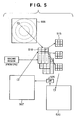
- Fig. 5 is a view for explaining sharpening processing according to the third embodiment, which improves the resolution distribution shown in Fig. 2 or Fig. 11A or 11B .
- an imaging region of a subject to be imaged is adopted in addition to the selection criterion for spatial filters which are described in the second embodiment. That is, filtering processing for preventing a deterioration in image quality due to excessive enhancement of X-ray quantum noise is performed in accordance with each imaging region.
- the reason why filtering processing is changed in accordance with each imaging region is that better results can be obtained by changing the frequency band for enhancement processing depending on the region to be imaged.
- a digital X-ray image obtained by imaging a bone such as a hand portion or leg portion of the subject contains many important information in a high-frequency region
- an image obtained by imaging the thoracic vertebrae or abdominal portion contains many important information in a low-frequency region.
- reference numeral 505 denotes resolution distribution data; 507, dose index data; 510, a spatial filter table; 515, a spatial filter; 520, an original image; and 525, a low-pass filter.
- the spatial filter 515 is selected in accordance with three indexes, i.e., indexes of resolution, X-ray dose, and imaging region.
- the spatial filter table 510 is therefore a three-dimensional table which can specify a spatial filter in accordance with three indexes, i.e., indexes of resolution, X-ray dose, and imaging region.
- an imaging region is selected by an OPU 100.
- one of the spatial filter tables 510 separately prepared for the respective imaging regions is selected.
- the selected single table corresponds to a two-dimensional spatial filter table (having the same arrangement as that of the spatial filter table 410 in the second embodiment).
- the spatial filter 515 is therefore selected from the two-dimensional spatial filter table corresponding to the imaging region on the basis of a resolution and X-ray dose.
- the original image 520 is then subjected to filtering processing.
- Changing the spatial filter 515 in consideration of the region to be imaged in the above manner makes it possible to optimize sharpening processing for the frequency band of the diagnosis region for each imaging region, thereby effectively supporting diagnosis by the doctor.
- a spatial filter may be selected in accordance with a resolution and imaging region, or may be selected from an X-ray dose or imaging region alone.
- Fig. 6 is a view for explaining filtering processing using the spatial filters 315, 415, and 515 described with reference to Fig. 3 to 5 .
- "*" represents convolution.
- filtering processing is performed as shown in Fig. 6 .
- a(m, n) corresponds to the spatial filters 315, 415, and 515.
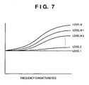
- Fig. 7 is a view for explaining the frequency characteristics of the spatial filters 315, 415, and 515 used in the respective embodiments described above.
- the spatial filters 315, 415, and 515 are obtained by Fourier-transforming and sampling the functions of frequency characteristics shown in Fig. 7 . That is, the characteristics of the respective spatial filters used as the spatial filters 315, 415, and 515 are determined by the frequency characteristics of the functions shown in Fig. 7 which show one-to-one correspondence with spatial filters.
- Fig. 7 increase in high-frequency component from level 1 to level N. This indicates that when filtering processing is performed by using the spatial filters 315, 415, and 515, the high-frequency components of an image are enhanced more strongly from level 1 to level N.
- spatial filters may be sequentially selected in increasing order of high-frequency components from level 1 to level N in accordance with the pixel positions at which the resolution gradually decreases.
- spatial filters may be selected in increasing order of high-frequency components from level 1 to level N with an increase in X-ray dose.
- spatial filters may be selected in increasing order of high-frequency components from level 1 to level N.
- F(M, X, P) be the function of a frequency domain in Fig. 7 .
- M represents the value of a presampling MTF
- X a pixel value proportional to an X-ray dose
- P an imaging region.
- F(M, X, P) becomes a function which increases a high-frequency component from level 1 to level N.
- F(M, X, P) becomes a function which increases a high-frequency component from level 1 to level N.
- P includes many higher-frequency components such as bones and fine blood vessels while M and X are fixed, F(M, X, P) becomes a function which increases a high-frequency component from level 1 to level N.
- Fig. 7 shows examples of functions which increase or decrease in all frequency regions. However, functions may be used, in which only a region of frequency components of a given portion monotonously increases or decreases with respect to the respective parameters M, X, and P.
- the resolution distribution of the X-ray detector 110 can be improved by selecting a spatial filter having frequency characteristics in which as the resolution decreases, or the X-ray dose increases, or a diagnosis region includes more fine high-frequency components, a high-frequency component increases from level 1 to level N.
- a digital X-ray image can be obtained, which has undergone optimal sharpening processing depending on the imaging region without excessive enhancement of X-ray quantum noise or system noise.
- Fig. 8 is a flowchart showing image restoration processing including improving processing for the resolution distribution of the X-ray detector 110, sharpening processing without excessive enhancement of noise, and optical sharpening processing for each imaging region.
- Processing according to the third embodiment which uses a resolution, X-ray dose, and imaging region to specify a spatial filter will be described.
- the processing according to the first embodiment is equivalent to the processing shown in Fig. 8 from which the portions associated with an X-ray dose and imaging region are omitted.
- the processing according to the second embodiment is equivalent to the processing shown in Fig. 8 from which the portion associated with an imaging region is omitted.
- step S101 the resolution distribution data (the resolution distribution data 305, 405, and 505 in Figs. 3 to 5 ) of an X-ray detector 110 is generated.
- the resolution distribution data can be obtained by measuring the presampling MTFs of the X-ray detector 110, as described above. Note that if the measurement value of the resolution distribution data of the X-ray detector 110 is stored, resolution distribution data need not be measured for every imaging operation. In order to also shorten the processing time, it is preferable that resolution distribution data be generated before imaging of the subject and the generated resolution distribution data be stored in an image processing unit 115.
- the resolution distribution data may be image data obtained by recording the value of a presampling MTF at a given spatial frequency as a pixel value as shown in Fig. 2 .
- the resolution distribution data may be segmented into concentric regions, as shown in Fig. 3 .
- step S102 an imaging region is designated by the OPU 100.
- the corresponding two-dimensional spatial filter table 510 is selected.
- X-ray imaging of the subject 105 is performed in step S103. More specifically, a digital X-ray image of the subject 105 is acquired from the X-ray detector 110 by irradiation with X-rays from an X-ray source 103.
- step S104 dose index data corresponding to the image obtained by imaging is generated.
- the low-pass filter 525 is applied to the digital X-ray original image 520 acquired from the X-ray detector 110 to generate the dose index data 507.
- step S105 the positions of the resolution distribution data 505 of a processing target pixel, the dose index data 507, and the original image 520 are determined.
- step S106 a resolution index corresponding to the pixel position determined in step S105 is acquired from the resolution distribution data 505.
- step S107 a dose index corresponding to the pixel position determined in step S105 is acquired from the dose index data 507.
- step S108 the spatial filter 515 corresponding to the resolution index and dose index acquired in steps S106 and S107 are acquired from the spatial filter table 510 corresponding to the imaging region selected in step S102.
- step S109 the computation described with reference to Fig. 6 is performed by using the spatial filter 515 selected in step S108.
- the processing from step S105 to step S109 described above is executed for all the pixels of the image 520 as a processing target (step S110).
- a digital X-ray image can be optimally sharpened, thereby providing a digital X-ray image that facilitates diagnosis.
- FIG. 9 is a view for explaining how an image is restored by a restoration filter.
- Fig. 9 shows an example of a technique using a restoration filter as a technique of improving resolution deterioration like that shown in Fig. 11B .
- the result obtained by Fourier-transforming a PSF (Point Spread Function) representing system deterioration corresponds to the presampling MTF in Fig. 11B .
- PSF Point Spread Function
- an original image (ideal image) (f) has the resolution deterioration (A) described above, and noise (n) such as X-ray quantum noise or system noise produced from a circuit or the like in the apparatus is added to the image to result in acquiring an observation image (g) like that acquired by the X-ray detector 110 as a digital X-ray image.
- noise (n) such as X-ray quantum noise or system noise produced from a circuit or the like in the apparatus is added to the image to result in acquiring an observation image (g) like that acquired by the X-ray detector 110 as a digital X-ray image.
- a restoration filter (B) like the one shown in Fig. 9 is applied to this observation image, a restored image (f') is obtained.
- Restoration filters include a projection filter, homomorphous filter, Wiener filter, and the like.
- K( ⁇ , ⁇ ) is the Wiener filter
- Wn( ⁇ , ⁇ ) is the power spectrum of the noise (n) shown in Fig. 9
- Wf( ⁇ , ⁇ ) is the power spectrum of the original image (f) shown in Fig.
- H( ⁇ , ⁇ ) is the presampling MTF of the X-ray detector 110 like that shown in Fig. 11A .
- the filter represented by equation (2) or the like is applied to the digital X-ray image, the resolution of the digital X-ray image is improved.
- Wn( ⁇ , ⁇ ) indicates the power of noise.
- Wn( ⁇ , ⁇ )/Mean 2 is inversely proportional to the square of the SNR of the image dominated by X-ray quantum noise.
- Wf( ⁇ , ⁇ )/Mean 2 corresponds to the power spectrum of the imaged subject which does not depend on the imaging dose, and changes depending on the imaging region. Therefore, Wn( ⁇ , ⁇ )/Wf( ⁇ , ⁇ ) is a parameter dependent on the imaging region and X-ray dose in equation (2).
- H( ⁇ , ⁇ ) is the presampling MTF of the X-ray detector 110.
- a change in resolution in the X-ray detector 110 corresponds to a change in H( ⁇ , ⁇ ). That is, in equation (2), H( ⁇ , ⁇ ) is a parameter which changes in accordance with the resolution distribution in the X-ray detector 110.
- the functions described with reference to Fig. 7 are expressed by equation (2) in the above manner.
- the spatial filters 315, 415, and 515 are obtained.
- Equation (2) As K( ⁇ , ⁇ ) increases, the enhancement degree of the processed image increases. Assume that Wn( ⁇ , ⁇ )/Wf( ⁇ , ⁇ ) in equation (2) is interpreted as the division between Wn( ⁇ , ⁇ )/Mean 2 and Wf( ⁇ , ⁇ )/Mean 2 . In this case, as the X-ray dose increases, Wn( ⁇ , ⁇ )/Mean 2 decreases, and K( ⁇ , ⁇ ) increases, resulting in an increase in the enhancement degree of the processed image.
- the enhancement processing represented by equation (2) is the processing in which the enhancement degree changes in accordance with the resolution of the X-ray detector 110, an X-ray dose, and an imaging region.
- the spatial filters 315, 415, and 515 described in this embodiment can be realized by using even general restoration filters, and a digital X-ray image optimally sharpened for diagnosis can be obtained.
- Equation (2) continuously changes in accordance with the resolution of the X-ray detector 110, an X-ray dose, and an imaging region.
- the spatial filter table 510 may be generated upon discretely setting resolutions, X-ray doses, and imaging regions in advance, and stored in the image processing unit 115. Storing the spatial filter table in advance makes it possible to increase the processing speed.
- the spatial filters 315, 415, and 515 may be derived from equation (2) at the time of imaging operation.
- edge enhancement filtering processing like unsharp masking processing (Kak Rosenfeld, "Digital Picture Processing", supervised and translated by Makoto Nagao, Kindaikagakusha) can realize similar effects by multiplying a filter by a coefficient which changes depending on a resolution, X-ray dose, and imaging region. Similar effects can be realized by establishing a mathematical expression expressing enhancement processing such that as the X-ray dose increases, the enhancement degree of a processed image increases, whereas as the resolution of the X-ray detector 110 decreases, the enhancement degree of the processed image increases.
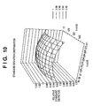
- Fig. 10 is a view for explaining one example of a resolution distribution data generating method which can be used in the first to third embodiments.
- the graph of Fig. 10 shows the normalized standard deviation distribution of the digital X-ray image acquired from the X-ray detector 110.
- the standard deviation of a digital X-ray image greatly depends on the resolution if the X-ray dose remains the same. This graph indicates that the standard deviation value decreases concentrically on the digital X-ray image in spite of irradiation with X-rays with a uniform dose. This indicates that the resolution decreases concentrically unless there is no X-ray absorption efficiency distribution. Therefore, this standard deviation and the presampling MTF shown in Fig. 11B have a correlation. For this reason, the resolution distribution of the X-ray detector 110 can be obtained from the standard deviation distribution.
- the standard deviation distribution of the X-ray dose detected from the X-ray image obtained by performing calibration imaging of the X-ray detector 110 X-ray imaging without no object between the X-ray detector 110 and the X-ray source 103 at the same tube voltage as that set for imaging of the subject. Since the resolution distribution of the X-ray detector 110 can be estimated from this standard deviation distribution, this standard deviation distribution can be used as resolution distribution data 305, 405, and 505.
- Generating the resolution distribution data 305, 405, and 505 by calibration imaging of the X-ray detector 110 can save the labor of measuring presampling MTFs on the entire surface of the X-ray detector 110. This makes it possible to easily generate the resolution distribution data 305, 405, and 505.
- an image processing method of processing the image obtained by the X-ray detector 110 serving as an image sensor According to this method, the resolution distribution (305, 405, and 505 in Figs. 2 and 10 ) of the X-ray detector 110 is held, a resolution corresponding to a pixel of interest is obtained from the resolution distribution, and sharpening processing at the level selected in accordance with the resolution is executed (image processing unit 115, S106, S108). According to this embodiment, the resolution distribution of the X-ray detector can be improved, and a digital X-ray image suitable for diagnosis can be provided.
- the pixel value of a pixel of interest is obtained by applying the spatial filter (305, 405, or 505) selected in accordance with the resolution.
- an X-ray dose distribution is acquired on the basis of the image obtained by the X-ray detector 110 (dose index data 407, dose index data 507, LPF 425, LPF 525), and a sharpening processing level is selected on the basis of the resolution obtained from the resolution distribution with respect to the pixel of interest and the X-ray dose obtained from the X-ray dose distribution.
- the resolution distribution of the X-ray detector can be improved, and a digital X-ray image suitable for diagnosis can be provided without excessive enhancement of X-ray quantum noise or system noise.
- a sharpening processing level is selected in consideration of the imaging region of the image obtained from the X-ray detector, and hence the resolution distribution of the X-ray detector can be improved, and sharpening processing suitable for the imaging region can be done without excessive enhancement of X-ray quantum noise or system noise, thereby providing a digital X-ray image suitable for diagnosis.
- a resolution distribution may also be generated on the basis of the presampling MTF measured with respect to the X-ray detector, or may be acquired on the basis of the standard deviation obtained by uniformly irradiating the X-ray detector with X-rays.
- the image processing apparatus including the X-ray detector 110 and the image processing unit 115 which holds the resolution distribution of the X-ray detector 110, obtains a resolution corresponding to a pixel of interest of the image obtained by the X-ray detector 110 from the resolution distribution, and executes sharpening processing at the level selected in accordance with the resolution.
- the X-ray imaging apparatus including the X-ray source 103 which emits X-rays, the X-ray detector 110 which detects the X-rays emitted from the X-ray source 103, the image processing unit 115 which holds the resolution distribution of the X-ray detector 110, obtains a resolution corresponding to a pixel of interest of the image obtained from the X-ray detector 110 from the resolution distribution, and executes sharpening processing at the level selected in accordance with the resolution, and the image output unit 120 which outputs the processed image.
- the object of the present invention is realized even by supplying a storage medium storing software program codes for realizing the functions of the above-described embodiments to a system or apparatus, and causing the computer (or a CPU or an MPU) of the system or apparatus to read out and execute the program codes stored in the storage medium.
- the program codes read out from the storage medium realize the functions of the above-described embodiments by themselves, and the storage medium storing the program codes constitutes the present invention.
- a storage medium for supplying the program codes a flexible disk, hard disk, optical disk, magnetooptical disk, CD-ROM, CD-R, magnetic tape, nonvolatile memory card, ROM, or the like can be used.
- the image quality of an image obtained from an image sensor having a resolution distribution can be effectively improved.
Landscapes
- Engineering & Computer Science (AREA)
- Physics & Mathematics (AREA)
- General Physics & Mathematics (AREA)
- Theoretical Computer Science (AREA)
- Health & Medical Sciences (AREA)
- Life Sciences & Earth Sciences (AREA)
- Medical Informatics (AREA)
- Radiology & Medical Imaging (AREA)
- Surgery (AREA)
- Nuclear Medicine, Radiotherapy & Molecular Imaging (AREA)
- Optics & Photonics (AREA)
- Pathology (AREA)
- Biophysics (AREA)
- Biomedical Technology (AREA)
- Heart & Thoracic Surgery (AREA)
- Molecular Biology (AREA)
- High Energy & Nuclear Physics (AREA)
- Animal Behavior & Ethology (AREA)
- General Health & Medical Sciences (AREA)
- Public Health (AREA)
- Veterinary Medicine (AREA)
- Image Processing (AREA)
- Apparatus For Radiation Diagnosis (AREA)
- Facsimile Image Signal Circuits (AREA)
Claims (11)
- Procédé de traitement d'image consistant à traiter une image obtenue à partir d'un capteur d'image sur lequel est agencée une plaque de luminophore formée par croissance cristalline d'un luminophore en des formes d'aiguilles inégales, comprenant :une première étape d'acquisition consistant à acquérir une définition correspondant à un pixel de l'image auquel on s'intéresse à partir d'une distribution de définitions du capteur d'image qui est contenue dans une mémoire ;une étape de choix consistant à choisir, sur la base de la définition acquise, à partir d'une table de filtres spatiaux, un filtre spatial qui renforce le pixel auquel on s'intéresse ; etune étape de filtrage consistant à effectuer un traitement de filtrage sur le pixel auquel on s'intéresse en utilisant le filtre spatial choisi,dans lequel, à ladite étape de choix, on choisit un filtre spatial de façon que le degré de renforcement d'un pixel de l'image auquel on s'intéresse augmente à mesure que diminue la définition du pixel de l'image auquel on s'intéresse,caractérisé :en ce que le filtre spatial est choisi à partir de filtres spatiaux 1 à N, dans lequel les caractéristiques de fréquences des filtres spatiaux 1 à N augmentent dans une composante à haute fréquence d'un niveau 1 à un niveau N pour les filtres spatiaux 1 à N, dans lequel le filtre spatial est choisi à partir des filtres spatiaux 1 à N de façon que la composante à haute fréquence augmente du niveau 1 au niveau N à mesure que diminue la définition du pixel de l'image auquel on s'intéresse, etdans lequel le procédé comprend en outre une seconde étape d'acquisition consistant à acquérir une distribution de doses de rayons X sur la base d'une image obtenue à partir du capteur d'image, eten ce que, à l'étape de choix, le filtre spatial pour le pixel auquel on s'intéresse est choisi sur la base d'une définition obtenue à partir de la distribution de définitions et d'une dose de rayons X obtenue à partir de la distribution de doses de rayons X.
- Procédé selon la revendication 1, dans lequel le filtre spatial est choisi en tenant compte d'une région de formation d'image d'une image obtenue à partir du capteur d'image.
- Procédé selon la revendication 1, dans lequel le filtre spatial est choisi de façon que le degré de renforcement d'un pixel auquel on s'intéresse augmente à mesure que la dose de rayons X augmente.
- Procédé selon la revendication 1, dans lequel la distribution de définitions est engendrée sur la base d'une fonction de transfert de modulation (MTF) de pré-échantillonnage mesurée en ce qui concerne le capteur d'image.
- Procédé selon la revendication 1, dans lequel la distribution de définitions est obtenue sur la base d'un écart type obtenu en éclairant uniformément le capteur d'image à l'aide de rayons X.
- Dispositif de traitement d'image comprenant :un capteur d'image sur lequel est agencée une plaque de luminophore formée par croissance cristalline d'un luminophore en des formes d'aiguilles inégales ;une unité de détention constituée pour détenir une distribution de définitions dudit capteur d'image ;une première unité d'acquisition constituée pour acquérir une définition correspondant à un pixel de l'image auquel on s'intéresse à partir d'une distribution de définitions du capteur d'image détenue par ladite unité de détention ;une unité de choix constituée pour choisir, sur la base de la définition acquise, à partir d'une table de filtres spatiaux, un filtre spatial qui renforce le pixel auquel on s'intéresse ; etune unité de filtrage constituée pour effectuer un traitement de filtrage sur le pixel auquel on s'intéresse en utilisant le filtre spatial choisi,dans lequel, ladite unité de choix, est constituée pour choisir un filtre spatial de façon que le degré de renforcement d'un pixel de l'image auquel on s'intéresse augmente à mesure que diminue la définition du pixel de l'image auquel on s'intéresse,caractérisé :en ce que ladite unité de choix est constituée pour choisir le filtre spatial à partir de filtres spatiaux 1 à N, dans lequel les caractéristiques de fréquences des filtres spatiaux 1 à N augmentent dans une composante à haute fréquence d'un niveau 1 à un niveau N pour les filtres spatiaux 1 à N, dans lequel ladite unité de choix est constituée pour choisir le filtre spatial à partir des filtres spatiaux 1 à N de façon que la composante à haute fréquence augmente du niveau 1 au niveau N à mesure que diminue la définition du pixel de l'image auquel on s'intéresse, etdans lequel le dispositif comprend en outre une seconde unité d'acquisition constituée pour acquérir une distribution de doses de rayons X sur la base d'une image obtenue à partir dudit capteur d'image, eten ce que ladite unité de choix est constituée pour choisir le filtre spatial pour le pixel auquel on s'intéresse sur la base d'une définition obtenue à partir de la distribution de définitions et d'une dose de rayons X obtenue à partir de la distribution de doses de rayons X.
- Dispositif selon la revendication 6, dans lequel le filtre spatial est choisi en tenant compte d'une région de formation d'image d'une image obtenue à partir dudit capteur d'image.
- Dispositif selon la revendication 6, dans lequel le filtre spatial est choisi de façon que le degré de renforcement d'un pixel auquel on s'intéresse augmente à mesure que la dose de rayons X augmente.
- Dispositif selon la revendication 6, dans lequel la distribution de définitions est engendrée sur la base d'une MTF de pré-échantillonnage mesurée en ce qui concerne le capteur d'image.
- Dispositif selon la revendication 6, dans lequel la distribution de définitions est obtenue sur la base d'un écart type obtenu en éclairant uniformément le capteur d'image à l'aide de rayons X.
- Appareil d'imagerie aux rayons X comprenant :le dispositif de traitement d'image selon la revendication 6 ;une source de rayons X qui émet des rayons X ;un détecteur de rayons X comportant le capteur d'image pour détecter les rayons X émis par ladite source de rayons X, dans lequel l'unité de détention est constituée pour détenir la distribution de définitions dudit détecteur de rayons X ; etune unité de sortie constituée pour sortir une image traitée par ladite unité de filtrage.
Applications Claiming Priority (2)
| Application Number | Priority Date | Filing Date | Title |
|---|---|---|---|
| JP2003164084A JP4412704B2 (ja) | 2003-06-09 | 2003-06-09 | 画像処理方法および装置並びにx線撮影装置 |
| JP2003164084 | 2003-06-09 |
Publications (3)
| Publication Number | Publication Date |
|---|---|
| EP1492050A2 EP1492050A2 (fr) | 2004-12-29 |
| EP1492050A3 EP1492050A3 (fr) | 2005-10-12 |
| EP1492050B1 true EP1492050B1 (fr) | 2012-04-11 |
Family
ID=33410880
Family Applications (1)
| Application Number | Title | Priority Date | Filing Date |
|---|---|---|---|
| EP04013490A Expired - Lifetime EP1492050B1 (fr) | 2003-06-09 | 2004-06-08 | Procédé et dispositif pour le traitement d'images et appareil de radiographie |
Country Status (5)
| Country | Link |
|---|---|
| US (1) | US8670040B2 (fr) |
| EP (1) | EP1492050B1 (fr) |
| JP (1) | JP4412704B2 (fr) |
| KR (1) | KR100629848B1 (fr) |
| CN (1) | CN100338527C (fr) |
Families Citing this family (17)
| Publication number | Priority date | Publication date | Assignee | Title |
|---|---|---|---|---|
| JP2007029681A (ja) * | 2005-07-22 | 2007-02-08 | Hitoshi Imamura | 歯科用デジタルx線画像処理方法 |
| JP2008073208A (ja) * | 2006-09-21 | 2008-04-03 | Konica Minolta Medical & Graphic Inc | 画像処理装置及び画像処理方法 |
| JP5562919B2 (ja) * | 2011-09-30 | 2014-07-30 | オリンパス株式会社 | 超解像観察装置 |
| US8942444B2 (en) * | 2012-08-17 | 2015-01-27 | General Electric Company | System and method for image compression in X-ray imaging systems |
| JP6097524B2 (ja) * | 2012-10-29 | 2017-03-15 | キヤノン株式会社 | 画像処理方法、画像処理装置、およびプログラム |
| KR20150021231A (ko) | 2013-08-20 | 2015-03-02 | 주식회사바텍 | 스캔 영상의 복원 방법, 장치 및 이를 저장하는 기록매체 |
| CN104574284A (zh) * | 2013-10-24 | 2015-04-29 | 南京普爱射线影像设备有限公司 | 一种数字x射线图像对比度增强处理方法 |
| JP5992633B2 (ja) * | 2013-10-31 | 2016-09-14 | 富士フイルム株式会社 | 画像処理装置及び撮像装置 |
| JP2015167789A (ja) * | 2014-03-10 | 2015-09-28 | キヤノン株式会社 | 被検体情報取得装置および信号処理方法 |
| WO2016158196A1 (fr) * | 2015-03-31 | 2016-10-06 | 富士フイルム株式会社 | Dispositif de capture d'images et procédé et programme de traitement d'images destinés à un dispositif de traitement d'images |
| KR101850871B1 (ko) * | 2015-08-26 | 2018-04-23 | 주식회사 디알텍 | 방사선 영상의 처리방법 및 방사선 촬영시스템 |
| US20180372888A1 (en) * | 2015-12-14 | 2018-12-27 | Carestream Health, Inc. | Radiation Sensing Thermoplastic Composite Panels |
| EP3391380B1 (fr) | 2015-12-14 | 2020-09-23 | Carestream Dental Technology Topco Limited | Plaques composites thermoplastiques de détection de rayonnement |
| JP2019508707A (ja) * | 2015-12-14 | 2019-03-28 | ケアストリーム・デンタル・テクノロジー・トプコ・リミテッド | 放射線感受性熱可塑性複合パネル |
| JP7837722B2 (ja) * | 2021-03-31 | 2026-03-31 | キヤノン株式会社 | 放射線撮影システム、放射線撮影方法、及び、プログラム |
| WO2022221279A1 (fr) * | 2021-04-12 | 2022-10-20 | Georgia Tech Research Corporation | Dosimétrie de rayonnement à l'aide d'un dispositif informatique mobile |
| CN113701628A (zh) * | 2021-08-20 | 2021-11-26 | 中国铁道科学研究院集团有限公司 | 接触线磨耗动态测量方法及装置 |
Family Cites Families (34)
| Publication number | Priority date | Publication date | Assignee | Title |
|---|---|---|---|---|
| KR880000085B1 (ko) * | 1985-05-22 | 1988-02-23 | 가부시기가이샤 히다찌메디코 | X선 단층 촬영장치(x線斷層撮影裝置) |
| CN1012705B (zh) * | 1986-08-25 | 1991-05-29 | 株式会社岛津制作所 | X射线图象摄影装置 |
| JPH06205768A (ja) * | 1992-08-18 | 1994-07-26 | Philips Electron Nv | X線検査装置 |
| JP3542377B2 (ja) * | 1993-06-04 | 2004-07-14 | キヤノン株式会社 | 画像形成装置及びその方法 |
| JP3066944B2 (ja) | 1993-12-27 | 2000-07-17 | キヤノン株式会社 | 光電変換装置、その駆動方法及びそれを有するシステム |
| US5715334A (en) * | 1994-03-08 | 1998-02-03 | The University Of Connecticut | Digital pixel-accurate intensity processing method for image information enhancement |
| US5600574A (en) * | 1994-05-13 | 1997-02-04 | Minnesota Mining And Manufacturing Company | Automated image quality control |
| JP3466790B2 (ja) * | 1995-08-15 | 2003-11-17 | コニカミノルタホールディングス株式会社 | 放射線画像情報読取方法及び放射線画像情報読取装置 |
| US5696850A (en) * | 1995-12-21 | 1997-12-09 | Eastman Kodak Company | Automatic image sharpening in an electronic imaging system |
| EP0823691B1 (fr) * | 1996-08-08 | 2003-12-17 | Agfa-Gevaert | Méthode de correction d'images de rayonnement quant aux défauts dans le matériel d'enregistrement |
| US6197218B1 (en) * | 1997-02-24 | 2001-03-06 | Superior Micropowders Llc | Photoluminescent phosphor powders, methods for making phosphor powders and devices incorporating same |
| US7578582B2 (en) * | 1997-07-15 | 2009-08-25 | Silverbrook Research Pty Ltd | Inkjet nozzle chamber holding two fluids |
| US6449390B1 (en) * | 1997-09-24 | 2002-09-10 | Canon Kabushiki Kaisha | Image processing apparatus and method therefor |
| US6057889A (en) * | 1997-09-26 | 2000-05-02 | Sarnoff Corporation | Format-responsive video processing system |
| JPH11331592A (ja) * | 1998-05-12 | 1999-11-30 | Canon Inc | 画像読み取り装置及びコンピュータ読み取り可能な記憶媒体 |
| US6628329B1 (en) * | 1998-08-26 | 2003-09-30 | Eastman Kodak Company | Correction of position dependent blur in a digital image |
| US6205198B1 (en) * | 1998-09-16 | 2001-03-20 | Canon Kabushiki Kaisha | Exposure compensation for digital radiography systems using spatial look-up tables |
| JP2000115539A (ja) * | 1998-09-30 | 2000-04-21 | Fuji Photo Film Co Ltd | 画像処理方法、画像処理装置及び記録媒体 |
| US6392249B1 (en) * | 1998-10-13 | 2002-05-21 | Agfa-Gevaert | Method for recording and reproducing images made by penetrating radiation using electroluminescent elements |
| FR2786648B1 (fr) * | 1998-11-30 | 2001-01-05 | Commissariat Energie Atomique | Procede de correction des defauts d'images issues d'un detecteur de rayons x ou y de type matriciel |
| US6987831B2 (en) * | 1999-11-18 | 2006-01-17 | University Of Rochester | Apparatus and method for cone beam volume computed tomography breast imaging |
| EP1257972B1 (fr) * | 2000-02-02 | 2006-12-06 | Quvis, Inc. | Systeme et procede permettant d'optimiser la resolution d'images au moyen de dispositifs d'imagerie pixelises |
| US6707057B2 (en) * | 2000-03-23 | 2004-03-16 | Agfa-Gevaert | Storage phosphor screen with thick outermost layer and a method for using the same |
| US20030138742A1 (en) * | 2000-04-11 | 2003-07-24 | Nikon Corporation | Exposure method and exposure apparatus |
| AU2001294604A1 (en) * | 2000-09-22 | 2002-04-02 | Numerix Llc | Improved radiation therapy treatment method |
| US6993183B2 (en) * | 2001-03-13 | 2006-01-31 | Canon Kabushiki Kaisha | Image processing apparatus, image processing system, image processing method, and computer-readable storage medium |
| EP1301031A1 (fr) * | 2001-09-29 | 2003-04-09 | Philips Corporate Intellectual Property GmbH | Méthode de correction des charactéristiques de transfert différentes de capteurs d' images |
| JP2003190125A (ja) * | 2001-12-27 | 2003-07-08 | Konica Corp | 画像処理装置、画像処理方法、プログラム、及び記憶媒体 |
| EP1355483A1 (fr) * | 2002-03-22 | 2003-10-22 | Fuji Photo Film Co., Ltd. | Méthode et appareil pour corriger la netteté d'image dans un appareil de lecture |
| US7545976B2 (en) * | 2002-05-01 | 2009-06-09 | Hewlett-Packard Development Company, L.P. | Method and apparatus for associating image enhancement with color |
| US7385217B2 (en) * | 2002-08-15 | 2008-06-10 | Konica Corporation | Radiation image photographing system |
| US7233101B2 (en) * | 2002-12-31 | 2007-06-19 | Samsung Electronics Co., Ltd. | Substrate-supported array having steerable nanowires elements use in electron emitting devices |
| US6809465B2 (en) * | 2002-08-23 | 2004-10-26 | Samsung Electronics Co., Ltd. | Article comprising MEMS-based two-dimensional e-beam sources and method for making the same |
| EP2261932A3 (fr) * | 2002-11-27 | 2011-09-28 | Konica Minolta Holdings, Inc. | Panneau pour la conversion d'images obtenues par rayonnement, procédé pour sa fabrication, procédé pour fabriquer des particules luminescentes, procédé pour fabriquer un précurseur d'un matériau luminescent stimulable, précurseur d'un matériau luminescent et matériau luminescent stimulable |
-
2003
- 2003-06-09 JP JP2003164084A patent/JP4412704B2/ja not_active Expired - Fee Related
-
2004
- 2004-05-26 CN CNB2004100428097A patent/CN100338527C/zh not_active Expired - Fee Related
- 2004-06-01 US US10/857,816 patent/US8670040B2/en not_active Expired - Fee Related
- 2004-06-08 EP EP04013490A patent/EP1492050B1/fr not_active Expired - Lifetime
- 2004-06-08 KR KR1020040041719A patent/KR100629848B1/ko not_active Expired - Fee Related
Non-Patent Citations (5)
| Title |
|---|
| BERGSTROM M. ET AL: "CORRECTION FOR SCATTERED RADIATION IN A RING DETECTOR POSITRON CAMERA BY INTERRAL TRANSFORMATION OF THE PROJECTIONS", JOURNAL OF COMPUTER ASSISTED TOMOGRAPHY, NEW YORK, NY, US, vol. 7, no. 1, 1 February 1983 (1983-02-01), pages 42 - 50, XP009052384 * |
| BOONE J M ET AL: "AN ANALYTICAL MODEL OF THE SCATTERED RADIATION DISTRIBUTION IN DIAGNOSTIC RADIOLOGY", MEDICAL PHYSICS, AIP, MELVILLE, NY, US, vol. 15, no. 5, 1 September 1988 (1988-09-01), pages 721 - 725, XP000007100, ISSN: 0094-2405, DOI: 10.1118/1.596186 * |
| BRIX G. ET AL: "Use of scanner characteristics in iterative image reconstruction for high-resolution positron emission tomography studies of small animals", EUROPEAN JOURNAL OF NUCLEAR MEDICINE, SPRINGER, BERLIN, HEIDELBERG, DE, vol. 24, no. 7, 1 July 1997 (1997-07-01), pages 779 - 786, XP002318420, ISSN: 0340-6997 * |
| PERRY, STUART WILLIAM: "ADAPTIVE IMAGE PROCESSING", 2002, CRC PRESS, ISBN: 9780849302831, pages: 44 - 45 * |
| SEIBERT J A ET AL: "X-ray scatter removal by deconvolution", MEDICAL PHYSICS, AIP, MELVILLE, NY, US, vol. 15, no. 4, 1 July 1988 (1988-07-01), pages 567 - 575, XP002340970, ISSN: 0094-2405, DOI: 10.1118/1.596208 * |
Also Published As
| Publication number | Publication date |
|---|---|
| US8670040B2 (en) | 2014-03-11 |
| EP1492050A2 (fr) | 2004-12-29 |
| JP4412704B2 (ja) | 2010-02-10 |
| KR20040105616A (ko) | 2004-12-16 |
| US20040246347A1 (en) | 2004-12-09 |
| JP2005005792A (ja) | 2005-01-06 |
| KR100629848B1 (ko) | 2006-09-29 |
| CN100338527C (zh) | 2007-09-19 |
| CN1573532A (zh) | 2005-02-02 |
| EP1492050A3 (fr) | 2005-10-12 |
Similar Documents
| Publication | Publication Date | Title |
|---|---|---|
| EP1492050B1 (fr) | Procédé et dispositif pour le traitement d'images et appareil de radiographie | |
| US7418078B2 (en) | Spot-size effect reduction | |
| US7623691B2 (en) | Method for helical windmill artifact reduction with noise restoration for helical multislice CT | |
| Kyprianou et al. | Generalizing the MTF and DQE to include x‐ray scatter and focal spot unsharpness: Application to a new microangiographic system | |
| US5878108A (en) | Method for generating X-ray image and apparatus therefor | |
| US20030091222A1 (en) | Method for contrast-enhancement of digital portal images | |
| US7362845B2 (en) | Method and apparatus of global de-noising for cone beam and fan beam CT imaging | |
| EP2572641B1 (fr) | Dispositif de traitement d'une image radiographique | |
| US20040258201A1 (en) | Radiography apparatus and radiography method | |
| US20040223583A1 (en) | Radiographic image processing method and radiation imaging device | |
| US6801647B1 (en) | Method and apparatus for evaluating digital radiation image | |
| US7668361B2 (en) | System and method for the correction of temporal artifacts in tomographic images | |
| US7433086B2 (en) | Edge detection and correcting system and method | |
| JPH10314152A (ja) | X線撮影装置 | |
| JP4137499B2 (ja) | 位相情報復元方法及び位相情報復元装置、並びに、位相情報復元プログラム | |
| JP4137580B2 (ja) | 位相情報復元方法及び位相情報復元装置、並びに、位相情報復元プログラム | |
| Yu et al. | A novel grid regression demodulation method for radiographic grid artifact correction | |
| JP4258092B2 (ja) | 画像処理装置および画像処理方法 | |
| Seibert | Computed radiography technology 2004 | |
| JP4261125B2 (ja) | 位相情報復元方法及び位相情報復元装置、並びに、位相情報復元プログラム | |
| JP2005177495A (ja) | 放射線画像処理の方法及び装置 | |
| KR20110083848A (ko) | 엑스선 촬영장치 | |
| Seeram | Computed Radiography Imaging: Physical Principles and System Components | |
| JP3465028B2 (ja) | 放射線画像情報の読取り方法 | |
| JP4137505B2 (ja) | 位相情報復元方法及び位相情報復元装置、並びに、位相情報復元プログラム |
Legal Events
| Date | Code | Title | Description |
|---|---|---|---|
| PUAI | Public reference made under article 153(3) epc to a published international application that has entered the european phase |
Free format text: ORIGINAL CODE: 0009012 |
|
| AK | Designated contracting states |
Kind code of ref document: A2 Designated state(s): AT BE BG CH CY CZ DE DK EE ES FI FR GB GR HU IE IT LI LU MC NL PL PT RO SE SI SK TR |
|
| AX | Request for extension of the european patent |
Extension state: AL HR LT LV MK |
|
| PUAL | Search report despatched |
Free format text: ORIGINAL CODE: 0009013 |
|
| AK | Designated contracting states |
Kind code of ref document: A3 Designated state(s): AT BE BG CH CY CZ DE DK EE ES FI FR GB GR HU IE IT LI LU MC NL PL PT RO SE SI SK TR |
|
| AX | Request for extension of the european patent |
Extension state: AL HR LT LV MK |
|
| 17P | Request for examination filed |
Effective date: 20060412 |
|
| AKX | Designation fees paid |
Designated state(s): DE FR GB IT NL |
|
| 17Q | First examination report despatched |
Effective date: 20060630 |
|
| GRAP | Despatch of communication of intention to grant a patent |
Free format text: ORIGINAL CODE: EPIDOSNIGR1 |
|
| GRAS | Grant fee paid |
Free format text: ORIGINAL CODE: EPIDOSNIGR3 |
|
| GRAA | (expected) grant |
Free format text: ORIGINAL CODE: 0009210 |
|
| AK | Designated contracting states |
Kind code of ref document: B1 Designated state(s): DE FR GB IT NL |
|
| REG | Reference to a national code |
Ref country code: GB Ref legal event code: FG4D |
|
| REG | Reference to a national code |
Ref country code: DE Ref legal event code: R096 Ref document number: 602004037245 Country of ref document: DE Effective date: 20120606 |
|
| REG | Reference to a national code |
Ref country code: NL Ref legal event code: T3 |
|
| PLBE | No opposition filed within time limit |
Free format text: ORIGINAL CODE: 0009261 |
|
| STAA | Information on the status of an ep patent application or granted ep patent |
Free format text: STATUS: NO OPPOSITION FILED WITHIN TIME LIMIT |
|
| 26N | No opposition filed |
Effective date: 20130114 |
|
| REG | Reference to a national code |
Ref country code: DE Ref legal event code: R097 Ref document number: 602004037245 Country of ref document: DE Effective date: 20130114 |
|
| PGFP | Annual fee paid to national office [announced via postgrant information from national office to epo] |
Ref country code: GB Payment date: 20140610 Year of fee payment: 11 |
|
| PGFP | Annual fee paid to national office [announced via postgrant information from national office to epo] |
Ref country code: NL Payment date: 20140613 Year of fee payment: 11 Ref country code: DE Payment date: 20140630 Year of fee payment: 11 Ref country code: IT Payment date: 20140604 Year of fee payment: 11 |
|
| PGFP | Annual fee paid to national office [announced via postgrant information from national office to epo] |
Ref country code: FR Payment date: 20140625 Year of fee payment: 11 |
|
| REG | Reference to a national code |
Ref country code: DE Ref legal event code: R119 Ref document number: 602004037245 Country of ref document: DE |
|
| PG25 | Lapsed in a contracting state [announced via postgrant information from national office to epo] |
Ref country code: IT Free format text: LAPSE BECAUSE OF NON-PAYMENT OF DUE FEES Effective date: 20150608 |
|
| GBPC | Gb: european patent ceased through non-payment of renewal fee |
Effective date: 20150608 |
|
| REG | Reference to a national code |
Ref country code: NL Ref legal event code: MM Effective date: 20150701 |
|
| REG | Reference to a national code |
Ref country code: FR Ref legal event code: ST Effective date: 20160229 |
|
| PG25 | Lapsed in a contracting state [announced via postgrant information from national office to epo] |
Ref country code: DE Free format text: LAPSE BECAUSE OF NON-PAYMENT OF DUE FEES Effective date: 20160101 Ref country code: GB Free format text: LAPSE BECAUSE OF NON-PAYMENT OF DUE FEES Effective date: 20150608 Ref country code: NL Free format text: LAPSE BECAUSE OF NON-PAYMENT OF DUE FEES Effective date: 20150701 |
|
| PG25 | Lapsed in a contracting state [announced via postgrant information from national office to epo] |
Ref country code: FR Free format text: LAPSE BECAUSE OF NON-PAYMENT OF DUE FEES Effective date: 20150630 |