EP1492288A2 - Mehrbenutzerdetektion für drahtlose Übertragungssysteme in Gegenwart von Inteferenz - Google Patents
Mehrbenutzerdetektion für drahtlose Übertragungssysteme in Gegenwart von Inteferenz Download PDFInfo
- Publication number
- EP1492288A2 EP1492288A2 EP20040102920 EP04102920A EP1492288A2 EP 1492288 A2 EP1492288 A2 EP 1492288A2 EP 20040102920 EP20040102920 EP 20040102920 EP 04102920 A EP04102920 A EP 04102920A EP 1492288 A2 EP1492288 A2 EP 1492288A2
- Authority
- EP
- European Patent Office
- Prior art keywords
- unit
- received signal
- equalizer
- multiuser
- coupled
- Prior art date
- Legal status (The legal status is an assumption and is not a legal conclusion. Google has not performed a legal analysis and makes no representation as to the accuracy of the status listed.)
- Granted
Links
- 238000004891 communication Methods 0.000 title claims abstract description 56
- 238000001514 detection method Methods 0.000 title claims abstract description 55
- 238000000034 method Methods 0.000 claims abstract description 50
- 238000005070 sampling Methods 0.000 claims description 28
- 238000005314 correlation function Methods 0.000 claims description 5
- 230000005540 biological transmission Effects 0.000 abstract description 34
- 238000012549 training Methods 0.000 description 50
- 230000008569 process Effects 0.000 description 24
- 238000010586 diagram Methods 0.000 description 20
- 239000011159 matrix material Substances 0.000 description 12
- 230000008901 benefit Effects 0.000 description 8
- 230000001360 synchronised effect Effects 0.000 description 7
- 125000004122 cyclic group Chemical group 0.000 description 4
- 239000013598 vector Substances 0.000 description 4
- 238000004519 manufacturing process Methods 0.000 description 3
- 239000000203 mixture Substances 0.000 description 3
- 238000001914 filtration Methods 0.000 description 2
- 230000002452 interceptive effect Effects 0.000 description 2
- 238000012545 processing Methods 0.000 description 2
- 230000004044 response Effects 0.000 description 2
- 238000012935 Averaging Methods 0.000 description 1
- 238000007476 Maximum Likelihood Methods 0.000 description 1
- 230000004075 alteration Effects 0.000 description 1
- 239000000969 carrier Substances 0.000 description 1
- 230000010267 cellular communication Effects 0.000 description 1
- 238000010276 construction Methods 0.000 description 1
- 230000007423 decrease Effects 0.000 description 1
- 230000001419 dependent effect Effects 0.000 description 1
- 238000000605 extraction Methods 0.000 description 1
- 230000006872 improvement Effects 0.000 description 1
- 238000006467 substitution reaction Methods 0.000 description 1
- 230000001629 suppression Effects 0.000 description 1
Images



Classifications
-
- H—ELECTRICITY
- H04—ELECTRIC COMMUNICATION TECHNIQUE
- H04L—TRANSMISSION OF DIGITAL INFORMATION, e.g. TELEGRAPHIC COMMUNICATION
- H04L25/00—Baseband systems
- H04L25/02—Details ; arrangements for supplying electrical power along data transmission lines
- H04L25/0202—Channel estimation
- H04L25/0204—Channel estimation of multiple channels
-
- H—ELECTRICITY
- H04—ELECTRIC COMMUNICATION TECHNIQUE
- H04L—TRANSMISSION OF DIGITAL INFORMATION, e.g. TELEGRAPHIC COMMUNICATION
- H04L25/00—Baseband systems
- H04L25/02—Details ; arrangements for supplying electrical power along data transmission lines
- H04L25/0202—Channel estimation
- H04L25/0224—Channel estimation using sounding signals
- H04L25/0228—Channel estimation using sounding signals with direct estimation from sounding signals
-
- H—ELECTRICITY
- H04—ELECTRIC COMMUNICATION TECHNIQUE
- H04L—TRANSMISSION OF DIGITAL INFORMATION, e.g. TELEGRAPHIC COMMUNICATION
- H04L25/00—Baseband systems
- H04L25/02—Details ; arrangements for supplying electrical power along data transmission lines
- H04L25/0202—Channel estimation
- H04L25/024—Channel estimation channel estimation algorithms
- H04L25/0242—Channel estimation channel estimation algorithms using matrix methods
- H04L25/0244—Channel estimation channel estimation algorithms using matrix methods with inversion
Definitions
- the present invention relates generally to a system and method for digital wireless communications, and more particularly to a system and method for detecting transmissions from multiple users in a digital wireless communications system in the presence of interference.
- Interference is a major source of concern for the designers of wireless communications networks. Interference can reduce the overall performance of the communications system and if severe enough, cause the communications system to fail altogether. Interference can come from other electrical and electronic devices operating in the general vicinity and from other devices in the same communications network that are transmitting in the same (or adjacent) frequency band.
- Interference from other devices in the same communications network can become a problem as designers of the communication network attempt to increase network capacity.
- one way to increase network capacity is to increase frequency reuse, i.e., allow devices that are relatively close to one another to transmit in the same frequency band.
- frequency reuse In cellular communications networks, adjacent cell sites typically do not operate in the same frequency bands. However, through cell site sectoring, frequency reuse can be increased, therefore increasing network capacity.
- devices, which are close to one another transmit in the same frequency band or in adjacent frequency bands, interference can occur.
- co-channel interference can occur, while adjacent channel interference can occur if devices transmit in adjacent bands if sufficient interband spacing is not provided.
- the information may become mixed together and it may be necessary to extract one (or more) user's information from a received signal.
- linear schemes can be used extract the desired information.
- GSM Global System for Mobile Telephony
- information is transmitted in bursts, wherein each burst may consist of two packets of data bits with a 26 bit mid-amble in between the two bursts.
- TSC training sequence codes
- SAIC single antenna interference cancellation
- a disadvantage of the prior art is that the complexity of the receiver can become very high, leading to complex and expensive receivers. For example, if the conventional receiver requires a 16-state Viterbi demodulator, then a joint MLSE (which suppresses a single interferer) could require 256 states.
- a method for extracting information transmitted by a desired user in a communications system from a received signal in the presence of interferers comprising derotating the received signal, determining channel estimates and detecting the presence of interferers, and extracting information transmitted by the desired user from the received signal.
- the method further comprises prior to the derotating, sampling the received signal at a given sampling rate.
- the received signal is transmitted at a symbol rate, and the sampling rate is essentially equal to the symbol rate.
- the received signal is transmitted at a symbol rate, and the sampling rate is higher than the symbol rate.
- the determining comprises: generating a list of hypotheses; computing an error variance for each hypothesis in the list of hypotheses; selecting a hypothesis associated with a smallest computed error variance; and computing channel estimates from the selected hypothesis.
- a hypothesis contains information about a desired user and any expected interferers.
- a hypothesis further contains timing offset information.
- the determining provides a number of users transmitting in the communications system, wherein the number of users provided by the determining includes the desired user, and wherein the extracting comprises: for each user, computing transmitted symbols; computing contribution of the transmitted symbols from the user; removing the computed contribution from the received signal; and the method further comprising, recomputing the transmitted symbols from the desired user.
- the first computing comprises applying a channel estimate for the user to the received signal.
- an equalizer is used to apply the channel estimate to the received signal.
- the second computing comprises multiplying the computed transmitted symbols with a channel estimate for the user.
- the desired user is a first user whose computed contribution is subtracted from the received signal
- the recomputing comprises: combining a received signal with the computed contribution from the first user removed with a received signal with the computed contributions from each user removed; and applying a channel estimate for the first user to the combined received signal.
- ordering of the users is performed.
- the ordering is based on at least one of the numbering of the users, the users' channel energy, SIR or SINR.
- the extracting can be repeated for the same set of transmitted symbols.
- the determining provides a number of users transmitting in the communications system
- the extracting comprises: applying the received signal to a plurality of matched filters, wherein there is one matched filter per number of users; providing outputs from the plurality of matched filters to a first decision feedback multiuser equalizer to compute an initial estimate of the information; providing outputs from the plurality of matched filters to a sequentially connected series of N decision feedback multiuser equalizers, wherein each decision feedback multiuser equalizer computes an intermediate estimate of the information based on an output of a previous decision feedback multiuser equalizer and a correlation; wherein N is an integer number representing a number of estimates of the information desired, and wherein output of the N-th decision feedback multiuser equalizer is the information.
- the number of matched filters is equal to a maximum number of unique users in the communications system.
- the method further comprises extracting a real component of the outputs from the plurality of matched filters.
- a receiver comprising a sampling unit coupled to a signal input, the sampling unit containing circuitry to sample a received signal provided by the signal input at a specified sampling rate, a channel estimation unit coupled to the sampling unit, the channel estimation unit containing circuitry to determine a number of users present in the received signal and to compute channel estimates for each user, and a multiuser detection unit coupled to the channel estimation unit, the multiuser detection unit containing circuitry to extract information transmitted by a desired user from the received signal.
- the multiuser detection unit can extract the information transmitted by the desired user in a single iteration, and wherein to improve upon the quality of the extracted information, the multiuser detection unit can repeatedly iterate on the received signal. Preferably the multiuser detection unit repeatedly iterates on the same received signal.
- the receiver further comprises a derotation unit having an input coupled to the sampling unit and an output coupled to the channel estimation unit and the multiuser detection unit, the derotation unit containing circuitry to apply a rotation of a specified amount to the sampled received signal.
- the multiuser detection unit comprises: a plurality of transmit symbol compute units coupled in a sequential fashion to a channel estimation unit, each symbol compute unit comprising, an equalizer containing circuitry to apply a channel estimate to an input signal to compute transmitted symbols for a user, wherein the input signal is the derotated sampled received signal if the transmit symbol compute unit is the first of the plurality, else the input signal is an output of a previous transmit symbol compute unit; a convolution unit coupled to the equalizer, the convolution unit to convolve an output of the equalizer with the channel estimate; and a summing point coupled to the input signal and the multiplier, the summing point to subtract an output of the convolution unit from the input signal; a final summing point coupled to an output of a final transmit symbol compute unit from the plurality and an output of the convolution unit from the first transmit symbol compute unit, the final summing point to add the two signals; and a final equalizer coupled to the final summing point, the final equalizer to re-estimate the
- the multiuser detection unit comprises: a plurality of matched filters coupled to a signal input line, each matched filter to apply a channel estimate for a unique user to a signal provided by the signal input line; a first decision feedback multiuser equalizer coupled to outputs of the plurality of matched filters, the first decision feedback multiuser equalizer containing circuitry to compute an initial estimate of the information transmitted by the desired user; a correlation unit coupled to the first decision feedback multiuser equalizer, the correlation unit containing circuitry to compute a correlation function based on channel estimates; and a plurality of decision feedback multiuser equalizers serially coupled together, wherein a first of the plurality is coupled to the first decision feedback multiuser equalizer, each decision feedback multiuser equalizer coupled to the outputs of the plurality of matched filters and the correlation unit, each decision feedback multiuser equalizer containing circuitry to compute an intermediate estimate of the information transmitted by the desired user based upon the correlation function, the outputs of the plurality of matched filters, and an output of a previous decision feedback multiuser equalizer
- the receiver is part of a wireless device used in a synchronous communications system.
- the synchronous communications system is a GSM compliant communications system.
- An advantage of a preferred embodiment of the present invention is that it is a simple, low-complexity method that can exploit the structure of the interference from other devices in the communications network to improve the performance of receivers.
- a further advantage of a preferred embodiment of the present invention is that a preferred embodiment of the present invention can be implemented upon existing receivers. This can facilitate a relatively easy implementation of the present invention on existing wireless communications networks.
- Yet another advantage of a preferred embodiment of the present invention is a simple non-linear detection algorithm that can be used to facilitate the detection of multiuser information in a receiver with a single antenna. Therefore, existing single antenna receivers can implement the detection algorithm, making the implementation of the present invention simpler.
- the present invention will be described with respect to preferred embodiments in a specific context, namely a GSM network operating in synchronous mode.
- the GSM technical standard can be found in a series of technical documents, wherein a general description can be found in Document 01.02, entitled “General Description of GSM Public Land Mobile Network (PLMN), Revision 6.0.0” published January 2001.
- PLMN Public Land Mobile Network
- the invention may also be applied, however, to other synchronous wireless communications networks which make use of known training sequences at specific locations within the transmission, such as GSM-EDGE (Enhanced Data Rates for GSM Evolution), GPRS (General Packet Radio Service), and so on.
- GSM-EDGE Enhanced Data Rates for GSM Evolution
- GPRS General Packet Radio Service
- FIG. 1 there is shown a diagram illustrating a transmission burst 100 in a GSM communications system.
- Data transmitted in the burst 100 are carried in a pair of 57-bit data fields 105.
- Two 3-bit fields, referred to as tail bit fields 110, can be used to keep adjacent bursts separate.
- transmissions are usually preceded with a field located at the beginning of the transmission. This field is commonly referred to as a preamble and can be used to carry a specific sequence of bits (typically referred to as a training sequence) that can help a receiver detect and decode the transmission. Note that while the use of a preamble is common, it is not the only place within a transmission to place a training sequence.
- the training sequence is located in the middle of the burst.
- the burst 100 contains a 26-bit training sequence field 115, which may be separated from the pair of 57-bit data fields 105 by a pair of stealing bit fields 120. Since the training sequence is not at the beginning of the transmission, it referred to as being a mid-amble. Note that the discussion of field specifics (the number of bits in a field, the position of a field, and so forth) is used to enable the discussion using a currently available wireless communications system. It should be evident that the field specifics should have no impact upon the spirit of the present invention.
- the GSM 26-bit training sequence field 115 can be broken up into three smaller fields, a 5-bit cyclic prefix field 205, a 16-bit training sequence field 210, and a 5-bit cyclic postfix field 215.
- the 5-bit cyclic prefix field 205 contains a copy of the last 5 bits of the 16-bit training sequence field 210 while the 5-bit cyclic postfix field 215 contains a copy of the first 5 bits of the 16-bit training sequence field 210.
- interference from other devices from within the same communications network can come in two forms, co-channel and adjacent channel interference. Regardless of the form of interference, the net result may be that the overall performance of the source of the interference and receiver of the interference may be degraded since the transmissions of both the device causing the interference and the device being interfered with are being damaged. Since the number of training sequences is limited (eight in the case of a GSM communications system), it can be possible to use the a priori knowledge of the training sequences to improve the channel estimation performance at a receiver.
- FIG. 3 there is shown a diagram illustrating the transmissions of three GSM devices, wherein there is no timing offset.
- Each of three sets of axes (305, 310, and 315) display a series of GSM bursts from a single device. Note that each device uses a different training sequence; TSC0 for the transmission displayed on axis 305, TSC2 for the transmission displayed on axis 310, and TSC1 for the transmission displayed on axis 315.
- TSC0 for the transmission displayed on axis 305
- TSC2 for the transmission displayed on axis 310
- TSC1 for the transmission displayed on axis 315.
- the GSM communications system displayed in Figure 3 is a synchronous system, wherein all of the devices transmit at essentially the same time.
- first GSM bursts 307, 312, and 317 are all transmitted at the same time, as are second GSM bursts 308, 313, and 318. Also note that there is no (or less than a single symbol) timing offset between the transmissions of the three devices.
- a vertical line 320 denotes the beginning of the second GSM bursts 308, 313, and 318 in all three devices.
- a timing offset exists between the arrival times of transmissions from different devices.
- a timing offset may exist even if transmissions within a wireless communications system are designed to occur at the same time. For example, if a clock of a transmitter has drifted away from clocks of other transmitters, then the transmitter with the inaccurate clock can begin its transmission at an incorrect time.
- differences in the distance traveled by various transmissions can also account for a timing offset. For example, even if transmissions are initiated at the same time, a transmission that is traveling a long distance will arrive later than a transmission that is traveling a short distance.
- a timing offset can vary from nanoseconds to milliseconds. When a timing offset is large, it can sometimes be expressed in terms of symbol intervals (an amount of time equal to the transmission of a single symbol).
- a baseband received signal can be sampled at a baud (symbol) rate to facilitate discrete-time processing.
- a Gaussian Minimum Shift Keying (GMSK) modulated signal can be accurately approximated using a linear approximation expressible as: wherein T is a single symbol duration and C 0 (t) is the GMSK waveform of duration 4 T .
- a derotation with j - ( m +1) can be performed on the baseband received signal, resulting in a signal that can be expressed as: Note that rather than using baud-rate sampling, oversampling (sub-baud-rate sampling) can also be performed if needed.
- FIG. 4 there is shown a diagram illustrating a view of a portion of a receiver 400, according to a preferred embodiment of the present invention.
- Figure 4 provides a high-level view of a portion responsible for interference suppression and multiuser detection in the receiver 400. Note that Figure 4 does not show typical parts that may be found in a receiver, such as an antenna, radio frequency hardware, decoding hardware, and so forth.
- a received signal, r(t) as received by an antenna (not shown) of the receiver 400 and after filtering to remove out-of-band interferers and amplifying to bring signal levels to a compatible level by radio frequency hardware (also not shown), may be sampled at baud-rate (or sub-baud-rate) by a baud-rate sampling unit 405. After sampling, the sampled received signal can be provided to a derotation unit 410, wherein the samples may be derotated by a specified amount, for example, by j -( m +1) .
- the derotated signal, r m can then be provided to a channel estimation unit 415, wherein the presence of information from users in the derotated signal can be detected and channel estimations can be computed.
- the channel estimates, ⁇ i may then be provided to a non-linear multiuser detection unit 420 where the information, â i,m , from the users can be extracted from the derotated signal, r m , and provided to portions of the receiver 400 that may be responsible for decoding, error detecting and correcting, and using the information (all are not shown). Details of the operation of the channel estimation unit 415 and the non-linear multiuser detection unit 420 will be provided below.
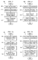
- FIG. 5 there is shown a flow diagram illustrating a process 500 for manipulating a signal received by a receiver and providing co-channel and adjacent channel interference and multiuser detection information and data from the received signal to circuitry and devices coupled to the receiver, according to a preferred embodiment of the present invention.
- the process 500 may execute on a controller or processor located in the receiver.
- the process 500 can be used in a receiver operating in a synchronous wireless communications system. If the wireless communications system is an asynchronous system, then the present invention may not operate properly.
- a wireless communications system that can operate either synchronously or asynchronously (such as a GSM based system)
- the process 500 can be used. However, if the wireless communications system has been detected as operating in asynchronous mode, then the process 500 can be turned off.
- a scheme that can rapidly detect the operating mode of a wireless communications system is disclosed and discussed in the co-pending and commonly assigned patent application entitled "Interferer Detection and Channel Estimation for Wireless Communications Systems.”
- the processor can begin the manipulation of the received signal after it has been transmitted over-the-air and detected by an antenna.
- the received signal may receive analog signal processing in the form of filtering (to remove out-of-band interference, for example) and amplifying (to bring the received signal to a signal level that is compatible with circuitry in the receiver) by radio frequency (RF) circuitry located in the receiver.
- RF radio frequency
- the received signal, r(t) can be sampled at a specified sampling rate (block 505). If the sampling rate is approximately equal to the symbol rate, then the sampling can be referred to as baud-rate sampling. If the sampling rate is higher than the symbol rate, then the sampling can be referred to as over sampling, with typical oversampling rates being two-, four-, eight-times higher than the symbol rate.
- the receive signal becomes a discrete time signal and can then be derotated (block 510). The derotation can be performed by multiplying the discrete time signal (the individual samples of the received signal) by a factor of j -(m +1) , for example.
- the received signal now denoted r m
- the received signal can be processed in order to detect the presence of interference from transmissions made by other users within the same wireless communications system as the desired user (block 515).
- a number of interferers can be determined and channel estimates for the different users can be computed.
- FIG. 6 there is show a detailed view of a process 600 for detecting interference in a received signal and computing channel estimations based upon the detected interference, according to a preferred embodiment of the present invention.
- the process 600 can be used for the detection of interference and channel estimation based on the interference (block 515 in Figure 5).
- the process 600 can begin with the generation of a list of possible hypotheses (block 605).
- the list of possible hypotheses can be dependent upon the total number of possible interferers and possible timing offsets.
- the number of possible timing offsets may be provided by the receiver and computed from the list of non-serving carriers (detectable transmitters operating in the area). For example, in a GSM communications system, wherein there is a limit of eight (8) unique training sequences, then the total number of possible interferers is seven (7) since one of the eight training sequences is used by the desired transmission.
- the list of possible hypotheses could include:
- an error variance can be computed (block 610).
- the process 600 may be provided with samples of the training sequences from recent bursts received by the receiver for use in the computation of the error variance.
- the joint least square error technique can be used to compute both the error variance and the channel estimation.
- the joint least squares technique is only one of several techniques that can be used. Other techniques, such as: recursive least squares (RLS) and least mean squares (LMS) can be used in place of the joint least squares technique.
- RLS recursive least squares
- LMS least mean squares
- iterative channel estimation in which initial channel estimates are used to make data decisions (before or after equalization) may be used.
- the data bits can be used as virtual pilot symbols to improve the channel estimation in one or more iterations.
- iterative channel estimation can also be used in asynchronous communications systems.
- the entire mid-amble (all 26 bits for a GSM communications system) can be used in conjunction with the least squares channel estimation. By using more data, performance may be improved.
- S is a circulant matrix formed from the training sequence used by the serving carrier. Let the training sequence be denoted as s (with K elements, typically 26), which contains elements that are each +1 or -1.
- the terms of the received signal can also be expressed as:
- the joint least squares channel estimates from the sum of two signals with different training signals is found by concatenating the h vectors and S matrices as shown below. Let h 1 be the channel for the first signal and h 2 be the channel for the second signal and S 1 and S 2 be the circulant matrices corresponding to the training sequences of the two signals.
- h ⁇ ⁇ J (S J H S J ) -1 S J H r ⁇ .
- a correlation can be used to estimate the channel.
- the sum of the squared errors for a single signal can be expressed as: where I is the identity matrix. Similarly, for joint least squares channel estimates, the sum of the squared error can be expressed as:
- the receiver may make use of the channel estimates to reconstruct the samples from the M samples of the mid-amble and then subtract from the originally received mid-amble to compute the sum of the squared errors.
- the computed error variances for each of the hypothesis can be compared and then a channel estimate for the hypothesis corresponding to the lowest computed error variance can be used (block 615). For example, if the computed error variance for Hypothesis #5 was found to be the lowest, then the receiver knows that in addition to its desired transmitted signal, a transmission using training sequence 5 is also present. This information can then be used to compute channel estimates (block 620).
- the process 500 can now extract information from the received signal (block 520).
- a receiver has a single antenna. Therefore, a non-linear multiuser detection scheme may be needed.
- a successive (serial) multiuser detection scheme and a parallel multiuser detection scheme can be used to extract information from the received signal.
- the process 700 can begin by computing transmitted symbols that can be attributable to a user k, ⁇ a k,m ⁇ (block 705).
- the user may be the user transmitting the desired signal or one of the interferers.
- the contribution to the received signal corresponding to the user k, (h k ⁇ a k ) m can be constructed (block 710).
- the contribution to the received signal corresponding to user k can then be subtracted from the received signal itself (block 715).
- These operations (blocks 705, 710, and 715) can be repeated for each of the K users.
- the contributions from all of the interfering users may have been subtracted from the received signal and the information corresponding to the user transmitting the desired signal can be re-estimated (block 720).
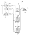
- the successive multiuser detection circuit 800 can be constructed from multiple iterations of a structure 802 that can be used to compute the transmitted symbols for a user k, ⁇ a k,m ⁇ , the contribution of the transmitted symbols for user k to the received signal, (h k ⁇ a k ) m , and subtracting the contribution of the transmitted symbols for user k from the received signal.
- An equalizer 805 can be used to compute the transmitted symbols for a user k, ⁇ a k,m ⁇ .
- the equalizer 805 can have the received signal minus the contribution of the transmitted symbols from users 1 to k -1. Note that if k is equal to 1, then the input to the equalizer 805 is the received signal.
- the equalizer 805 can also have as a second input, the channel estimate for user k (block 620 of Figure 6). Note that the equalizer 805 can be any arbitrary single-user equalizer such as a maximum likelihood sequence estimator (MLSE) trellis-based equalizer or one of many different types of decision-feedback equalizers.
- the symbol estimates provided by the equalizers can be soft, hard, or something in between.
- Figure 8 depicts a single pass of successive interference cancellation.
- additional performance gains can be obtained by repeating the K or K+1 iterations multiple times. For example, to obtain a better estimate of the transmitted symbols from the desired user, the K or K+1 iterations can be repeated.
- a convolution unit 810 can be used to convolve the output of the equalizer 805 with the channel estimate for user k.
- the output of the convolution unit 810 can be the contribution of the transmitted symbols for user k to the received signal and can be subtracted from the received signal by summing point 815.
- Output from the K -th structure 802 which is the received signal minus the contributions of the transmitted symbols from users 1 to k , can then be summed with contribution of the transmitted symbol from user 1 (without loss of generality, it was assumed that user 1 was the user transmitting the desired information) by a summing point 820.
- Output of the summing point 820 can be provided to a final equalizer 825 that can be used to re-estimate the transmitted symbols from user 1.
- the final equalizer 825 may also have as input, the channel estimate for user 1.
- the successive multiuser detection circuit 800 does not use any particular detection ordering (it simply performs its operation in sequential order). Some performance improvement can be obtained by using some sort of detection ordering. For example, an ordering based on channel energy, ⁇ ⁇ h k ⁇ 2 ⁇ . Alternatively, ordering based upon signal to interference ratio (SIR) or signal to interference plus noise ratio (SINR) can also be used. If detection ordering is used, a total of K iterations may be needed if the desired user is detected last.
- SIR signal to interference ratio
- SINR signal to interference plus noise ratio
- the process 750 can begin by applying a set of K matched filters (corresponding to the K users) to the received signal, r m , resulting in ⁇ y k,m ⁇ (block 755). Note that since the underlying modulation format of ⁇ a k , m ⁇ is real valued, only the real portion of the outputs of the matched filters is needed (block 760). Then, in an initial stage (stage 0), the process 750 can generate initial symbol estimates for ⁇ a k,m ⁇ (block 765). Then, for N successive stages, the symbol estimates for one of the remaining users can be computed symbol estimates from the previous stage and correlations which can be computed from channel estimates (block 770).
- MUI total multiuser interference
- a decision feedback multiuser equalizer (not shown) can be used to compute the symbols estimates.
- a stage- n multiuser equalizer can perform a forward-backward intersymbol interference (ISI) cancellation based upon the previous symbol estimates (for each m ): wherein W (n) is a weighting matrix for stage- n .
- the choice of W (n) can be arbitrary.
- the operator ⁇ . ⁇ can be a K -input K -output non-linear decision device.
- This decision device can generate fully hard (+/- 1) or soft estimates.
- it can be a classical linear clipped slicer.
- a preferred implementation of the decision device can be a conditional expectation estimator, expressible as: wherein C (n) is a covariance matrix of the residual interference plus the noise at stage-n and ⁇ 1 , ⁇ 2 , ⁇ , ⁇ 2 K ⁇ ⁇ ⁇ -1,+1 ⁇ K is a signal constellation.
- the covariance matrix can be modeled as an arbitrary non-negative definite symmetric matrix. However, results of experimentation have shown that the off-diagonal terms of the matrix (the cross correlation terms) tend to be small.
- ⁇ 2( n ) k ⁇ 2( n ) k ⁇ can serve as threshold parameters, which can be fixed or computed adaptively (based upon the received signal). Note that ⁇ 2( n ) 1 decreases with n as symbol estimates become more reliable at the latter stages.
- the variance parameters, ⁇ 2( n ) k can be computed adaptively from the mid-amble data which carries the training sequence symbols. The computation can be updated every transmission burst.
- (.) indicates an averaging operation over m within the mid-amble.
- stage- n 1,2,..., N :
- the parallel multiuser detection circuit 900 includes a matched filter bank 905, wherein there may be a matched filter 910 for each expected user in a received signal.
- a parallel multiuser detection circuit used in these communications systems can have a different number of matched filters 910.
- Each matched filter 910 can have two inputs, with a first input being the received signal, r m , and a second input being a channel estimate for user k, with the resulting output being signal ⁇ y k , m ⁇ .
- a first decision feedback multiuser equalizer (stage 0) 920 may be used to compute the initial estimates of ⁇ a k,m ⁇ ( â (0) m ) from the outputs of the real-valued circuits 915.
- Output from the first decision feedback multiuser equalizer 920 ( â (0) m ) can then be provided to a second decision feedback multiuser equalizer 925.
- output from a stage- n decision feedback multiuser equalizer can become input to a stage-( n +1) decision feedback multiuser equalizer.
- the first decision feedback multiuser equalizer 920 (and subsequent decision feedback multiuser equalizers) may also receive as input a correlation, R , that can be computed from channel estimates.
- the correlation, R may be computed from the channel estimates by a compute correlation circuit 930 and may be expressed as: A detailed description of the correlation can be found above.
- the output of a ( N +1) decision feedback multiuser equalizer 935 can be the desired information, â ( N ) m , transmitted by the desired user.
- the process 500 can continue to process addition information as further transmission bursts are received. If no further transmission bursts are received, the receiver may be placed in a sleep mode to save energy.
- FIG. 10 there is shown a diagram illustrating a comparison of bit-error rate (BER) versus carrier-to-interference ratio (CIR) for several multiuser detection schemes, according to a preferred embodiment of the present invention.
- a series of curves display the BER performance of four different multiuser detection schemes, with a first curve 1005 representing the performance of a receiver using conventional minimum least square error scheme, a second curve 1010 representing the performance of a receiver using a joint minimum least square error scheme, a third curve 1015 representing the performance of a receiver using successive multiuser detection scheme, and a fourth curve 1020 representing the performance of a receiver using parallel multiuser detection scheme.
- BER bit-error rate
- CIR carrier-to-interference ratio
Landscapes
- Engineering & Computer Science (AREA)
- Power Engineering (AREA)
- Computer Networks & Wireless Communication (AREA)
- Signal Processing (AREA)
- Physics & Mathematics (AREA)
- Mathematical Physics (AREA)
- Cable Transmission Systems, Equalization Of Radio And Reduction Of Echo (AREA)
- Monitoring And Testing Of Transmission In General (AREA)
- Noise Elimination (AREA)
Applications Claiming Priority (4)
| Application Number | Priority Date | Filing Date | Title |
|---|---|---|---|
| US48070303P | 2003-06-23 | 2003-06-23 | |
| US480703P | 2003-06-23 | ||
| US10/732,978 US7302233B2 (en) | 2003-06-23 | 2003-12-11 | Multiuser detection for wireless communications systems in the presence of interference |
| US732978 | 2003-12-11 |
Publications (3)
| Publication Number | Publication Date |
|---|---|
| EP1492288A2 true EP1492288A2 (de) | 2004-12-29 |
| EP1492288A3 EP1492288A3 (de) | 2005-08-10 |
| EP1492288B1 EP1492288B1 (de) | 2010-10-06 |
Family
ID=33424144
Family Applications (1)
| Application Number | Title | Priority Date | Filing Date |
|---|---|---|---|
| EP04102920A Expired - Lifetime EP1492288B1 (de) | 2003-06-23 | 2004-06-23 | Mehrbenutzerdetektion für drahtlose Übertragungssysteme in Gegenwart von Inteferenz |
Country Status (4)
| Country | Link |
|---|---|
| US (1) | US7302233B2 (de) |
| EP (1) | EP1492288B1 (de) |
| AT (1) | ATE484137T1 (de) |
| DE (1) | DE602004029422D1 (de) |
Cited By (5)
| Publication number | Priority date | Publication date | Assignee | Title |
|---|---|---|---|---|
| WO2005099155A1 (en) * | 2004-04-12 | 2005-10-20 | Nokia Corporation | I/q mimo detection for single antenna interference cancellation |
| EP1843533A1 (de) * | 2006-04-05 | 2007-10-10 | Research In Motion Limited | Verfahren und Empfänger zur Schätzung der Kanalimpulsantwort unter Verwendung eines Konstant-Modulus-Algorithmus |
| US8184744B2 (en) | 2006-04-05 | 2012-05-22 | Research In Motion Limited | Method and receiver for estimating the channel impulse response using a constant modulus interference removal iteration |
| EP1875617A4 (de) * | 2005-04-13 | 2013-05-01 | Ericsson Telefon Ab L M | Gleichzeitige kanalschätzung eines trägers und eines störers |
| EP2634923A1 (de) * | 2012-02-29 | 2013-09-04 | Fraunhofer-Gesellschaft zur Förderung der angewandten Forschung e.V. | Interferenzabschwächung in einem Kommunikationssystem |
Families Citing this family (13)
| Publication number | Priority date | Publication date | Assignee | Title |
|---|---|---|---|---|
| US8670705B2 (en) | 2003-07-30 | 2014-03-11 | Atc Technologies, Llc | Additional intra-and/or inter-system interference reducing systems and methods for satellite communications systems |
| US7340213B2 (en) | 2003-07-30 | 2008-03-04 | Atc Technologies, Llc | Intra- and/or inter-system interference reducing systems and methods for satellite communications systems |
| US7817754B2 (en) * | 2004-12-01 | 2010-10-19 | Bae Systems Information And Electronic Systems Integration Inc. | M-algorithm with prioritized user ordering |
| US20070002980A1 (en) * | 2005-06-29 | 2007-01-04 | Eyal Krupka | Method for timing and sequence hypotheses selection |
| US8781043B2 (en) * | 2006-11-15 | 2014-07-15 | Qualcomm Incorporated | Successive equalization and cancellation and successive mini multi-user detection for wireless communication |
| JP5596168B2 (ja) | 2009-11-27 | 2014-09-24 | クゥアルコム・インコーポレイテッド | 非直交チャネルセットのための干渉除去 |
| US8451964B2 (en) * | 2010-02-23 | 2013-05-28 | Qualcomm Incorporated | Code block interference cancellation |
| US8275077B1 (en) * | 2010-10-13 | 2012-09-25 | The United States Of America As Represented By The Director, National Security Agency | Coherent demodulation of ais-GMSK signals in co-channel |
| EP2740246A1 (de) * | 2011-08-04 | 2014-06-11 | BlackBerry Limited | Verfahren und system zum formatieren von zyklischem prefix / postfix in einem mobilen kommunikationssystem |
| US9014236B2 (en) * | 2011-09-28 | 2015-04-21 | Telefonaktiebolaget L M Ericsson (Publ) | Method, apparatus, receiver, computer program and storage medium for joint detection |
| US9166837B2 (en) | 2013-06-11 | 2015-10-20 | Qualcomm Incorporated | Base station assisted frequency domain equalization |
| US9602240B1 (en) * | 2015-09-11 | 2017-03-21 | Signalchip Innovations Private Limited | Method and system for symbol level interference cancellation at a receiver for multiuser detection |
| US20180213547A1 (en) | 2017-01-26 | 2018-07-26 | Electronics And Telecommunications Research Instit Ute | Communication node for scheduling and interference control in wireless communication network, and operation method therefor |
Family Cites Families (20)
| Publication number | Priority date | Publication date | Assignee | Title |
|---|---|---|---|---|
| US5818876A (en) * | 1993-02-01 | 1998-10-06 | Motorola, Inc. | Method and apparatus of adaptive maximum likelihood sequence estimation using a variable convergence step size |
| US6307868B1 (en) * | 1995-08-25 | 2001-10-23 | Terayon Communication Systems, Inc. | Apparatus and method for SCDMA digital data transmission using orthogonal codes and a head end modem with no tracking loops |
| US6628701B2 (en) * | 1997-06-11 | 2003-09-30 | Intel Corporation | Method and apparatus for reducing spread spectrum noise |
| SG77607A1 (en) * | 1997-08-26 | 2001-01-16 | Univ Singapore | A multi-user code division multiple access receiver |
| FR2774831B1 (fr) * | 1998-02-11 | 2000-04-07 | Agence Spatiale Europeenne | Recepteur adaptatif de signaux pour systeme de communications a acces pultiples par repartition a codes |
| US6366607B1 (en) * | 1998-05-14 | 2002-04-02 | Interdigital Technology Corporation | Processing for improved performance and reduced pilot |
| US6700923B1 (en) * | 1999-01-04 | 2004-03-02 | Board Of Regents The University Of Texas System | Adaptive multiple access interference suppression |
| US6426973B1 (en) * | 1999-04-29 | 2002-07-30 | The Board Of Trustees Of The University Of Illinois | Differential minimum mean squared error communication signal compensation method |
| DE19923407C1 (de) * | 1999-05-21 | 2000-08-24 | Siemens Ag | Empfangsverfahren und Empfangseinrichtung für Mobilfunkanwendungen |
| US6529495B1 (en) * | 1999-05-24 | 2003-03-04 | Nokia Telecommunications, Oy | Method and apparatus for providing differencing multistage detection in the reverse link of a code division multiple access communication system |
| US6463107B1 (en) * | 1999-07-01 | 2002-10-08 | Telefonaktiebolaget Lm Ericsson (Publ) | Methods and apparatuses for synchronization and modulation type detection |
| US6404760B1 (en) * | 1999-07-19 | 2002-06-11 | Qualcomm Incorporated | CDMA multiple access interference cancellation using signal estimation |
| US6856643B1 (en) * | 1999-10-22 | 2005-02-15 | Cwill Telecommunications, Inc. | Communication system and method for performing fast symbol estimation for multiple access disperse channels |
| US6628706B1 (en) * | 1999-12-06 | 2003-09-30 | Telefonaktiebolaget Lm Ericsson (Publ) | Method and apparatus for transforming a channel estimate |
| JP3846546B2 (ja) * | 2000-08-29 | 2006-11-15 | 日本電気株式会社 | 周波数オフセット推定器 |
| US6934317B1 (en) * | 2000-10-11 | 2005-08-23 | Ericsson Inc. | Systems and methods for communicating spread spectrum signals using variable signal constellations |
| US6920191B2 (en) * | 2001-02-02 | 2005-07-19 | Telefonaktiebolaget Lm Ericsson (Publ) | Estimation and compensation of the pulse-shape response in wireless terminals |
| US6967598B2 (en) * | 2004-02-20 | 2005-11-22 | Bae Systems Information And Electronic Systems Integration Inc | Reduced complexity multi-turbo multi-user detector |
| US7221699B1 (en) * | 2002-06-28 | 2007-05-22 | Arraycomm Llc | External correction of errors between traffic and training in a wireless communications system |
| US7243064B2 (en) * | 2002-11-14 | 2007-07-10 | Verizon Business Global Llc | Signal processing of multi-channel data |
-
2003
- 2003-12-11 US US10/732,978 patent/US7302233B2/en not_active Expired - Lifetime
-
2004
- 2004-06-23 EP EP04102920A patent/EP1492288B1/de not_active Expired - Lifetime
- 2004-06-23 DE DE602004029422T patent/DE602004029422D1/de not_active Expired - Lifetime
- 2004-06-23 AT AT04102920T patent/ATE484137T1/de not_active IP Right Cessation
Non-Patent Citations (5)
| Title |
|---|
| ARSLAN H ET AL.: "Co-channel interference cancellation with successive cancellation in narrowband TDMA systems", WIRELESS COMMUNICATIONS AND NETWORKING CONFERNCE, vol. 3, 23 September 2000 (2000-09-23), pages 1070 - 1 074 |
| ARSLAN H ET AL.: "Successive cancellation of adjacent channel signals in FDMNTDMA digital mobile radio systems", VEHICULAR TECHNOLOGY CONFERENCE, vol. 3, 18 May 1998 (1998-05-18), pages 1720 - 1724 |
| MEDEPALLI K; MANDAYAM N: "Combined equalization and cochannel interference cancellation for the downlink using tentative decisions", VEHICULAR TECHNOLOGY CONFERENCE, vol. 1, 16 May 1999 (1999-05-16), pages 637 - 641, XP010341942, DOI: doi:10.1109/VETEC.1999.778228 |
| PEKKA A. RANTA; MARKKU PUKKILA: "Radio aspects: Interference suppression by joint demodulation of co-channel signals", 1999, KLUWER ACADEMIC PUBLISHER |
| YOSHINO H ET AL.: "Interference canceling equalizer (ICE) for mobile radio communications", COMMUNICATIONS, 1994. ICC '94, SUPERCOMM/ICC '94, CONFERENCE RECORD, 1 May 1994 (1994-05-01), pages 1427 - 1432, XP000438732 |
Cited By (11)
| Publication number | Priority date | Publication date | Assignee | Title |
|---|---|---|---|---|
| WO2005099155A1 (en) * | 2004-04-12 | 2005-10-20 | Nokia Corporation | I/q mimo detection for single antenna interference cancellation |
| US7830975B2 (en) | 2004-04-12 | 2010-11-09 | Nokia Corporation | I/Q MIMO detection for single antenna interference cancellation |
| EP1875617A4 (de) * | 2005-04-13 | 2013-05-01 | Ericsson Telefon Ab L M | Gleichzeitige kanalschätzung eines trägers und eines störers |
| EP1843533A1 (de) * | 2006-04-05 | 2007-10-10 | Research In Motion Limited | Verfahren und Empfänger zur Schätzung der Kanalimpulsantwort unter Verwendung eines Konstant-Modulus-Algorithmus |
| EP2009859A1 (de) * | 2006-04-05 | 2008-12-31 | Research In Motion Limited | Verfahren und Empfänger zur Bewertung der Kanalimpulsreaktion bei einer konstanten Modulinterferenz-Entfernungsinteraktion |
| US8184744B2 (en) | 2006-04-05 | 2012-05-22 | Research In Motion Limited | Method and receiver for estimating the channel impulse response using a constant modulus interference removal iteration |
| US8842776B2 (en) | 2006-04-05 | 2014-09-23 | Blackberry Limited | Method and receiver for estimating the channel impulse response using a constant modulus interference removal iteration |
| EP2634923A1 (de) * | 2012-02-29 | 2013-09-04 | Fraunhofer-Gesellschaft zur Förderung der angewandten Forschung e.V. | Interferenzabschwächung in einem Kommunikationssystem |
| WO2013127688A2 (en) | 2012-02-29 | 2013-09-06 | Fraunhofer-Gesellschaft zur Förderung der angewandten Forschung e.V. | Interference mitigation in a communication system |
| WO2013127688A3 (en) * | 2012-02-29 | 2013-10-24 | Fraunhofer-Gesellschaft zur Förderung der angewandten Forschung e.V. | Interference mitigation in a communication system |
| US9124336B2 (en) | 2012-02-29 | 2015-09-01 | Fraunhofer-Gesellschaft Zur Foerderung Der Angewandten Forschung E.V. | Interference mitigation in a communication system |
Also Published As
| Publication number | Publication date |
|---|---|
| EP1492288A3 (de) | 2005-08-10 |
| US7302233B2 (en) | 2007-11-27 |
| US20040259504A1 (en) | 2004-12-23 |
| DE602004029422D1 (de) | 2010-11-18 |
| ATE484137T1 (de) | 2010-10-15 |
| EP1492288B1 (de) | 2010-10-06 |
Similar Documents
| Publication | Publication Date | Title |
|---|---|---|
| US6944245B2 (en) | Multi-pass interference reduction in a GSM communication system | |
| US7295636B2 (en) | Linear single-antenna interference cancellation receiver | |
| US7302233B2 (en) | Multiuser detection for wireless communications systems in the presence of interference | |
| US7187736B2 (en) | Reducing interference in a GSM communication system | |
| US8619928B2 (en) | Multi-stage interference suppression | |
| EP2883336B1 (de) | Gestapelte und verzweigte vamos-empfänger mit sukzessiver interferenzunterdrückung | |
| EP1569399B1 (de) | Empfänger zur Interferenzunterdrückung mit einer einzigen Antenne, mit verbesserter entscheidungsrückgekoppelter Entzerrung für GSM Systeme | |
| KR101047369B1 (ko) | 입력 노이즈 백색화필터의 적응형 동작에 의해 수신 신호를필터링하는 장치 및 관련 방법 | |
| CN101785193A (zh) | 具有干扰消除的gmsk接收器 | |
| WO2011163404A1 (en) | Signal reception method and apparatus for nonstationary channels | |
| EP2474138A2 (de) | Symbolschätzungsverfahren und -vorrichtungen | |
| EP1856797B1 (de) | Drahtlose kommunikationseinrichtung zur durchführung der blockentzerrung auf der basis von vorherigen, aktuellen und/oder zukünftigen autokorrelationsmatrix-schätzungen und diesbezügliche verfahren | |
| EP0508407B1 (de) | Maximalwahrscheinlichkeitsfolgeschätzung für sich schnell ändernde Mobilfunknachrichtenkanäle | |
| EP1748610B1 (de) | Vorrichtung, Verfahren und Computerprogram zur iterativen Kanalschätzung für ein OFDM Übertragungssystem | |
| EP1475932B1 (de) | Interferenzsignalerkennung und Kanalschätzung für drahtlose Kommunikationsnetze | |
| EP1892908A1 (de) | Empfänger und Verfahren zur Störungsunterdrückung | |
| Lee et al. | Separation of cochannel GSM signals using an adaptive array | |
| Dzung et al. | Performance of coherent data transmission in frequency-selective Rayleigh fading channels | |
| EP1475931B1 (de) | Methode und Apparat zur iterativen Schätzung von Filter- oder Kanalkoeffizienten | |
| Siala | Maximum a posteriori fast fading channel estimation based exclusively on pilot symbols | |
| CN101088226A (zh) | 无线接收器中的干扰抑制 | |
| EP1475933B1 (de) | Verfahren zur Störungsunterdrückung mittels einer iterativen, semi-blinden Kanalschätzung | |
| Oyerinde et al. | Iterative OFDM Receiver with Decision Directed Channel Estimation | |
| Moshfegh et al. | Optimized decision feedback equalizer and comparison with MLSE algorithm for GSM channel | |
| EP1103124A1 (de) | Empfänger für digitale signale, die in mehrwegkanälen übertragen werden |
Legal Events
| Date | Code | Title | Description |
|---|---|---|---|
| PUAI | Public reference made under article 153(3) epc to a published international application that has entered the european phase |
Free format text: ORIGINAL CODE: 0009012 |
|
| AK | Designated contracting states |
Kind code of ref document: A2 Designated state(s): AT BE BG CH CY CZ DE DK EE ES FI FR GB GR HU IE IT LI LU MC NL PL PT RO SE SI SK TR |
|
| AX | Request for extension of the european patent |
Extension state: AL HR LT LV MK |
|
| PUAL | Search report despatched |
Free format text: ORIGINAL CODE: 0009013 |
|
| AK | Designated contracting states |
Kind code of ref document: A3 Designated state(s): AT BE BG CH CY CZ DE DK EE ES FI FR GB GR HU IE IT LI LU MC NL PL PT RO SE SI SK TR |
|
| AX | Request for extension of the european patent |
Extension state: AL HR LT LV MK |
|
| 17P | Request for examination filed |
Effective date: 20060210 |
|
| AKX | Designation fees paid |
Designated state(s): AT BE BG CH CY CZ DE DK EE ES FI FR GB GR HU IE IT LI LU MC NL PL PT RO SE SI SK TR |
|
| RIN1 | Information on inventor provided before grant (corrected) |
Inventor name: DABAK, ANAND G. Inventor name: ONGGOSANUSI, EKO N. Inventor name: SCHMIDL, TIMOTHY M. |
|
| GRAP | Despatch of communication of intention to grant a patent |
Free format text: ORIGINAL CODE: EPIDOSNIGR1 |
|
| GRAS | Grant fee paid |
Free format text: ORIGINAL CODE: EPIDOSNIGR3 |
|
| GRAA | (expected) grant |
Free format text: ORIGINAL CODE: 0009210 |
|
| AK | Designated contracting states |
Kind code of ref document: B1 Designated state(s): AT BE BG CH CY CZ DE DK EE ES FI FR GB GR HU IE IT LI LU MC NL PL PT RO SE SI SK TR |
|
| REG | Reference to a national code |
Ref country code: GB Ref legal event code: FG4D |
|
| REG | Reference to a national code |
Ref country code: CH Ref legal event code: EP |
|
| REG | Reference to a national code |
Ref country code: IE Ref legal event code: FG4D |
|
| REF | Corresponds to: |
Ref document number: 602004029422 Country of ref document: DE Date of ref document: 20101118 Kind code of ref document: P |
|
| REG | Reference to a national code |
Ref country code: NL Ref legal event code: T3 |
|
| PG25 | Lapsed in a contracting state [announced via postgrant information from national office to epo] |
Ref country code: SI Free format text: LAPSE BECAUSE OF FAILURE TO SUBMIT A TRANSLATION OF THE DESCRIPTION OR TO PAY THE FEE WITHIN THE PRESCRIBED TIME-LIMIT Effective date: 20101006 |
|
| PG25 | Lapsed in a contracting state [announced via postgrant information from national office to epo] |
Ref country code: SE Free format text: LAPSE BECAUSE OF FAILURE TO SUBMIT A TRANSLATION OF THE DESCRIPTION OR TO PAY THE FEE WITHIN THE PRESCRIBED TIME-LIMIT Effective date: 20101006 Ref country code: FI Free format text: LAPSE BECAUSE OF FAILURE TO SUBMIT A TRANSLATION OF THE DESCRIPTION OR TO PAY THE FEE WITHIN THE PRESCRIBED TIME-LIMIT Effective date: 20101006 Ref country code: AT Free format text: LAPSE BECAUSE OF FAILURE TO SUBMIT A TRANSLATION OF THE DESCRIPTION OR TO PAY THE FEE WITHIN THE PRESCRIBED TIME-LIMIT Effective date: 20101006 Ref country code: BG Free format text: LAPSE BECAUSE OF FAILURE TO SUBMIT A TRANSLATION OF THE DESCRIPTION OR TO PAY THE FEE WITHIN THE PRESCRIBED TIME-LIMIT Effective date: 20110106 Ref country code: PT Free format text: LAPSE BECAUSE OF FAILURE TO SUBMIT A TRANSLATION OF THE DESCRIPTION OR TO PAY THE FEE WITHIN THE PRESCRIBED TIME-LIMIT Effective date: 20110207 |
|
| PG25 | Lapsed in a contracting state [announced via postgrant information from national office to epo] |
Ref country code: BE Free format text: LAPSE BECAUSE OF FAILURE TO SUBMIT A TRANSLATION OF THE DESCRIPTION OR TO PAY THE FEE WITHIN THE PRESCRIBED TIME-LIMIT Effective date: 20101006 Ref country code: GR Free format text: LAPSE BECAUSE OF FAILURE TO SUBMIT A TRANSLATION OF THE DESCRIPTION OR TO PAY THE FEE WITHIN THE PRESCRIBED TIME-LIMIT Effective date: 20110107 |
|
| PG25 | Lapsed in a contracting state [announced via postgrant information from national office to epo] |
Ref country code: EE Free format text: LAPSE BECAUSE OF FAILURE TO SUBMIT A TRANSLATION OF THE DESCRIPTION OR TO PAY THE FEE WITHIN THE PRESCRIBED TIME-LIMIT Effective date: 20101006 Ref country code: ES Free format text: LAPSE BECAUSE OF FAILURE TO SUBMIT A TRANSLATION OF THE DESCRIPTION OR TO PAY THE FEE WITHIN THE PRESCRIBED TIME-LIMIT Effective date: 20110117 Ref country code: CZ Free format text: LAPSE BECAUSE OF FAILURE TO SUBMIT A TRANSLATION OF THE DESCRIPTION OR TO PAY THE FEE WITHIN THE PRESCRIBED TIME-LIMIT Effective date: 20101006 |
|
| PLBE | No opposition filed within time limit |
Free format text: ORIGINAL CODE: 0009261 |
|
| STAA | Information on the status of an ep patent application or granted ep patent |
Free format text: STATUS: NO OPPOSITION FILED WITHIN TIME LIMIT |
|
| PG25 | Lapsed in a contracting state [announced via postgrant information from national office to epo] |
Ref country code: RO Free format text: LAPSE BECAUSE OF FAILURE TO SUBMIT A TRANSLATION OF THE DESCRIPTION OR TO PAY THE FEE WITHIN THE PRESCRIBED TIME-LIMIT Effective date: 20101006 Ref country code: DK Free format text: LAPSE BECAUSE OF FAILURE TO SUBMIT A TRANSLATION OF THE DESCRIPTION OR TO PAY THE FEE WITHIN THE PRESCRIBED TIME-LIMIT Effective date: 20101006 Ref country code: SK Free format text: LAPSE BECAUSE OF FAILURE TO SUBMIT A TRANSLATION OF THE DESCRIPTION OR TO PAY THE FEE WITHIN THE PRESCRIBED TIME-LIMIT Effective date: 20101006 Ref country code: PL Free format text: LAPSE BECAUSE OF FAILURE TO SUBMIT A TRANSLATION OF THE DESCRIPTION OR TO PAY THE FEE WITHIN THE PRESCRIBED TIME-LIMIT Effective date: 20101006 |
|
| 26N | No opposition filed |
Effective date: 20110707 |
|
| REG | Reference to a national code |
Ref country code: DE Ref legal event code: R097 Ref document number: 602004029422 Country of ref document: DE Effective date: 20110707 |
|
| PG25 | Lapsed in a contracting state [announced via postgrant information from national office to epo] |
Ref country code: IT Free format text: LAPSE BECAUSE OF FAILURE TO SUBMIT A TRANSLATION OF THE DESCRIPTION OR TO PAY THE FEE WITHIN THE PRESCRIBED TIME-LIMIT Effective date: 20101006 |
|
| REG | Reference to a national code |
Ref country code: CH Ref legal event code: PL |
|
| REG | Reference to a national code |
Ref country code: IE Ref legal event code: MM4A |
|
| PG25 | Lapsed in a contracting state [announced via postgrant information from national office to epo] |
Ref country code: CH Free format text: LAPSE BECAUSE OF NON-PAYMENT OF DUE FEES Effective date: 20110630 Ref country code: LI Free format text: LAPSE BECAUSE OF NON-PAYMENT OF DUE FEES Effective date: 20110630 Ref country code: IE Free format text: LAPSE BECAUSE OF NON-PAYMENT OF DUE FEES Effective date: 20110623 |
|
| PG25 | Lapsed in a contracting state [announced via postgrant information from national office to epo] |
Ref country code: MC Free format text: LAPSE BECAUSE OF NON-PAYMENT OF DUE FEES Effective date: 20110630 |
|
| PG25 | Lapsed in a contracting state [announced via postgrant information from national office to epo] |
Ref country code: CY Free format text: LAPSE BECAUSE OF FAILURE TO SUBMIT A TRANSLATION OF THE DESCRIPTION OR TO PAY THE FEE WITHIN THE PRESCRIBED TIME-LIMIT Effective date: 20101006 Ref country code: LU Free format text: LAPSE BECAUSE OF NON-PAYMENT OF DUE FEES Effective date: 20110623 |
|
| PG25 | Lapsed in a contracting state [announced via postgrant information from national office to epo] |
Ref country code: TR Free format text: LAPSE BECAUSE OF FAILURE TO SUBMIT A TRANSLATION OF THE DESCRIPTION OR TO PAY THE FEE WITHIN THE PRESCRIBED TIME-LIMIT Effective date: 20101006 |
|
| PG25 | Lapsed in a contracting state [announced via postgrant information from national office to epo] |
Ref country code: HU Free format text: LAPSE BECAUSE OF FAILURE TO SUBMIT A TRANSLATION OF THE DESCRIPTION OR TO PAY THE FEE WITHIN THE PRESCRIBED TIME-LIMIT Effective date: 20101006 |
|
| REG | Reference to a national code |
Ref country code: FR Ref legal event code: PLFP Year of fee payment: 13 |
|
| REG | Reference to a national code |
Ref country code: FR Ref legal event code: PLFP Year of fee payment: 14 |
|
| REG | Reference to a national code |
Ref country code: FR Ref legal event code: PLFP Year of fee payment: 15 |
|
| PGFP | Annual fee paid to national office [announced via postgrant information from national office to epo] |
Ref country code: DE Payment date: 20200518 Year of fee payment: 17 Ref country code: NL Payment date: 20200520 Year of fee payment: 17 Ref country code: FR Payment date: 20200520 Year of fee payment: 17 |
|
| PGFP | Annual fee paid to national office [announced via postgrant information from national office to epo] |
Ref country code: GB Payment date: 20200529 Year of fee payment: 17 |
|
| REG | Reference to a national code |
Ref country code: DE Ref legal event code: R119 Ref document number: 602004029422 Country of ref document: DE |
|
| REG | Reference to a national code |
Ref country code: NL Ref legal event code: MM Effective date: 20210701 |
|
| GBPC | Gb: european patent ceased through non-payment of renewal fee |
Effective date: 20210623 |
|
| PG25 | Lapsed in a contracting state [announced via postgrant information from national office to epo] |
Ref country code: GB Free format text: LAPSE BECAUSE OF NON-PAYMENT OF DUE FEES Effective date: 20210623 Ref country code: DE Free format text: LAPSE BECAUSE OF NON-PAYMENT OF DUE FEES Effective date: 20220101 |
|
| PG25 | Lapsed in a contracting state [announced via postgrant information from national office to epo] |
Ref country code: NL Free format text: LAPSE BECAUSE OF NON-PAYMENT OF DUE FEES Effective date: 20210701 Ref country code: FR Free format text: LAPSE BECAUSE OF NON-PAYMENT OF DUE FEES Effective date: 20210630 |