EP1492336A1 - Vorrichtung zur Bereitstellung eines Videosignals und Videoanzeigegerät - Google Patents
Vorrichtung zur Bereitstellung eines Videosignals und Videoanzeigegerät Download PDFInfo
- Publication number
- EP1492336A1 EP1492336A1 EP20040014137 EP04014137A EP1492336A1 EP 1492336 A1 EP1492336 A1 EP 1492336A1 EP 20040014137 EP20040014137 EP 20040014137 EP 04014137 A EP04014137 A EP 04014137A EP 1492336 A1 EP1492336 A1 EP 1492336A1
- Authority
- EP
- European Patent Office
- Prior art keywords
- video signal
- display device
- video
- analog
- video display
- Prior art date
- Legal status (The legal status is an assumption and is not a legal conclusion. Google has not performed a legal analysis and makes no representation as to the accuracy of the status listed.)
- Withdrawn
Links
- 238000000034 method Methods 0.000 claims description 9
- 230000007274 generation of a signal involved in cell-cell signaling Effects 0.000 description 10
- 238000010586 diagram Methods 0.000 description 4
- 230000005540 biological transmission Effects 0.000 description 2
- 230000006870 function Effects 0.000 description 2
- 230000002093 peripheral effect Effects 0.000 description 2
- 230000002411 adverse Effects 0.000 description 1
- 239000000470 constituent Substances 0.000 description 1
- 239000004973 liquid crystal related substance Substances 0.000 description 1
- 238000003825 pressing Methods 0.000 description 1
- 239000004065 semiconductor Substances 0.000 description 1
Images


Classifications
-
- H—ELECTRICITY
- H04—ELECTRIC COMMUNICATION TECHNIQUE
- H04N—PICTORIAL COMMUNICATION, e.g. TELEVISION
- H04N21/00—Selective content distribution, e.g. interactive television or video on demand [VOD]
- H04N21/40—Client devices specifically adapted for the reception of or interaction with content, e.g. set-top-box [STB]; Operations thereof
- H04N21/41—Structure of client; Structure of client peripherals
- H04N21/426—Internal components of the client ; Characteristics thereof
-
- H—ELECTRICITY
- H04—ELECTRIC COMMUNICATION TECHNIQUE
- H04N—PICTORIAL COMMUNICATION, e.g. TELEVISION
- H04N5/00—Details of television systems
- H04N5/44—Receiver circuitry for the reception of television signals according to analogue transmission standards
- H04N5/46—Receiver circuitry for the reception of television signals according to analogue transmission standards for receiving on more than one standard at will
-
- H—ELECTRICITY
- H04—ELECTRIC COMMUNICATION TECHNIQUE
- H04N—PICTORIAL COMMUNICATION, e.g. TELEVISION
- H04N21/00—Selective content distribution, e.g. interactive television or video on demand [VOD]
- H04N21/40—Client devices specifically adapted for the reception of or interaction with content, e.g. set-top-box [STB]; Operations thereof
- H04N21/43—Processing of content or additional data, e.g. demultiplexing additional data from a digital video stream; Elementary client operations, e.g. monitoring of home network or synchronising decoder's clock; Client middleware
- H04N21/436—Interfacing a local distribution network, e.g. communicating with another STB or one or more peripheral devices inside the home
- H04N21/4363—Adapting the video stream to a specific local network, e.g. a Bluetooth® network
- H04N21/43632—Adapting the video stream to a specific local network, e.g. a Bluetooth® network involving a wired protocol, e.g. IEEE 1394
-
- H—ELECTRICITY
- H04—ELECTRIC COMMUNICATION TECHNIQUE
- H04N—PICTORIAL COMMUNICATION, e.g. TELEVISION
- H04N21/00—Selective content distribution, e.g. interactive television or video on demand [VOD]
- H04N21/40—Client devices specifically adapted for the reception of or interaction with content, e.g. set-top-box [STB]; Operations thereof
- H04N21/47—End-user applications
- H04N21/485—End-user interface for client configuration
Definitions
- the present invention relates to a video signal supply device and a video display device that receives the supply of a video signal via a plurality of input terminals, for example.
- Japanese Patent Kokai (Laid Open Publication) No. 2002-344898 discloses a technology that connects a video signal supply device to a video display device through combined usage of a normal analog signal interface and a digital signal interface of the IEEE1394 Standard.
- the IEEE 1394 Standard is a standard standardized by the IEEE (American Institute of Electrical and Electronic Engineers) that regulates connections between computer devices and audiovisual devices, and between audiovisual devices and audiovisual devices. Under the IEEE 1394, it is possible to transmit digital signals at speeds on the order of several hundred megabits per second to several gigabits per second.
- the supply of a video signal from the DVD player to the television monitor can be executed via the analog interface or the IEEE1394 interface (digital interface).
- a single video display device such as a television monitor is often connected to a plurality of video signal supply devices.
- the video display device generally includes a plurality of analog signal input terminals suited to the respective video signal supply devices. Therefore, when the video signal supply from a DVD player to the television monitor is switched from "via an IEEE1394 interface" to "via an analog interface," the television monitor is unable to determine which analog signal input terminal the television monitor should select in order to receive a video signal from the DVD player.
- One object of the present invention is to provide a highly operable and user-friendly video signal supply device.
- Another object of the present invention is to provide a highly operable and user-friendly video display device.
- Still another object of the present invention is to provide an improved method for selecting suitable one of signal input terminals of a video display device.
- a video signal supply device adapted to supply, to a video display device that includes a digital signal input terminal and a plurality of analog signal input terminals, a digital signal via the digital signal input terminal and an analog video signal via one of the analog signal input terminals.
- the video signal supply device includes a first circuit for capturing and storing terminal designation information which specifies one of the analog signal input terminals.
- the video signal supply device also includes a second circuit for communicating the terminal designation information from the first circuit to the video display device via the digital signal input terminal when supply of the analog video signal to the video display device via the selected one of the analog signal input terminals is started.
- a video display device that includes a digital signal input terminal for receiving a digital signal from a video signal supply device. A terminal designation information is also supplied to the video display device from the video signal supply device via the digital signal input terminal.
- the video display device further includes a plurality of analog signal input terminals. An analog video signal is supplied to the video display device from the video signal supply device via one of the analog signal input terminals.
- the video display device also includes a circuit for selecting one of the analog signal input terminals, based on the terminal designation information supplied by the video signal supply device.
- a method for selecting one of a plurality of analog signal input terminals of a video display device when an analog video signal is supplied by a video signal supply device to the video display device via the selected one of the analog signal input terminals The video display device also includes a digital signal input terminal.
- the method includes capturing and storing terminal designation information which specifies one of the analog signal input terminals.
- the method also includes communicating the terminal designation information to the video display device via the digital signal input terminal when supply of the analog video signal from the video signal supply device to the video display device via one of the analog signal input terminals is started.
- the method also includes selecting one of the analog signal input terminals of the video display device, based on the terminal designation information communicated.
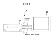
- the video signal supply system 8 includes a video signal supply device 10 and a video display device 20.
- the video signal supply device 10 is, for example, a DVD recorder that plays back video recording disks and outputs the played back video signal.
- the video display device 20 is a television monitor that uses a cathode ray tube, plasma display panel, or electroluminescent display panel, for example.
- the video display device 20 displays a video signal supplied by the video signal supply device 10.
- the video signal from the video signal supply device 10 is supplied to the video display device 20 via an analog interface or an IEEE1394 interface.
- the connection 9 between the video signal supply device 10 and video display device 20 may be a wired connection formed by an ordinary cable or a wireless connection that employs weak radio waves, infrared rays, or the like.
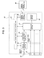
- the video signal supply device 10 has a control unit 11 (hereinafter referred to as the "first control unit 11").
- the first control unit 11 includes a microcomputer, a memory circuit including a ROM and RAM, and the peripheral circuits thereof.
- the first control unit 11 performs centralized control of the operation of the whole video signal supply device 10.
- the ROM in the memory circuit stores a variety of programs that regulate the operation of the video signal supply device 10.
- Various functions of the video signal supply device 10 are implemented as a result of the microcomputer running these programs one step at a time in sync with an internal clock. A variety of flags and various computational result values and so forth from this program execution process are temporarily stored in the RAM of the memory circuit.
- the first control unit 11 is connected, via the busline of the microcomputer, to the respective circuits in the video signal supply device 10, such as a recording device control unit 12, an IEEE1394 interface section 14 (hereinafter referred to as the “first interface section 14"), a video signal generation section 15 (hereinafter referred to as the “first video signal generation section 15”), and a remote control signal receiver 16 (hereinafter referred to as the “first remote control signal receiver 16").
- a recording device control unit 12 an IEEE1394 interface section 14
- a video signal generation section 15 hereinafter referred to as the "first video signal generation section 15”
- a remote control signal receiver 16 hereinafter referred to as the "first remote control signal receiver 16"
- the recording device control unit 12 is a control circuit that drives and controls a recording device 13, which is a recording medium for video signals or the like.
- the recording device control unit 12 may be constituted by an IC chip such as an LSI with special specifications.
- the recording device 13 is a large-capacity storage medium such as a hard disk device, and stores digital video data captured from a DVD or network distribution system (neither of which is shown).
- the first interface section 14 is a circuit that converts a variety of data including video data from the recording device 13 into a signal that is based on the IEEE1394 Standard on the basis of a predetermined protocol and timing, and sends the resulting signal to the IEEE1394 interface.
- the first video signal generation section 15 is a circuit that converts video data from the recording device 13 into an analog video signal and then outputs this analog video signal to an analog interface bus. The operations of the first interface section 14 and first video signal generation section 15 are controlled by the first control unit 11.
- the first remote control signal receiver 16 is a circuit that receives a command from a remote control signal transmitter 30 (hereinafter referred to as the "first remote control signal transmitter 30") and communicates this command to the first control unit 11.
- the first remote control signal transmitter 30 allows the user to issue commands for the various operations of the video signal supply device 10 and exchanges various data with the first remote control signal receiver 16 by using wireless media such as infrared rays, weak radio waves, or the like.
- the video display device 20 has a control unit 21 (hereinafter referred to as "second control unit 21").
- the second control unit 21 includes a second microcomputer, a second memory circuit including a ROM and RAM, and the peripheral circuits thereof.
- the second control unit 21 performs centralized control of the operation of the whole video display device 20.
- the ROM in the second memory circuit stores a variety of programs that regulate the operations of the video display device 20.
- Various functions of the video display device 20 are implemented as a result of the second microcomputer running these programs one step at a time in sync with an internal clock. A variety of flags and various computational result values and so forth of this program execution process are temporarily stored in the RAM of the second memory circuit.
- the second control unit 21 is connected, via the busline of the second microcomputer, to the respective circuits in the video display device 20, such as an IEEE1394 interface section 24 (hereinafter referred to as the "second interface section 24"), a video signal generation section 25 (hereinafter referred to as the “second video signal generation section 25"), a remote control signal receiver 26 (hereinafter referred to as the “second remote control signal receiver 26”), and a selector section 27, and so forth.
- the video display device 20 such as an IEEE1394 interface section 24 (hereinafter referred to as the "second interface section 24"), a video signal generation section 25 (hereinafter referred to as the "second video signal generation section 25"), a remote control signal receiver 26 (hereinafter referred to as the “second remote control signal receiver 26"), and a selector section 27, and so forth.
- the video display device 20 such as an IEEE1394 interface section 24 (hereinafter referred to as the "second interface section 24"), a video signal generation section 25 (hereinafter referred to
- the video display device 20 has a digital signal input terminal (or port) 22 to which digital signals of the IEEE1394 Standard are supplied from the video signal supply device 10.
- the digital signal input terminal 22 is constituted by connectors based on the IEEE1394 Standard.
- a so-called "daisy chain" is established, which connects the interface and devices by cables one after another.
- the daisy chain will not be described in detail here because no direct relationship exists between implementation of the embodiment of the invention and the daisy chain.
- the second interface section 24 is a circuit that exchanges data signals with the video signal supply device 10 via the digital signal input terminal 22 on the basis of a protocol and timing of the IEEE1394 Standard.
- the second video signal generation section 25 is a circuit that decodes IEEE1394 interface-format video data received by the second interface section 24 to an analog video signal and then outputs the analog video signal to the selector section 27. The operations of the second interface section 24 and second video signal generation section 25 are controlled by the second control unit 21.
- the video display device 20 also has an analog signal input terminal (or port) assembly 23 to receive analog video signals from the video signal supply device 10.
- an analog signal input terminal assembly 23 includes a plurality of signal input terminals from #1 to #n. That is, an analog video signal supplied by the video signal supply device 10 is connected to a certain terminal of the analog signal input terminal assembly 23.
- the selector section 27 is, for example, a video signal selection circuit that uses an FET or other semiconductor as a switching element.
- the selector section 27 selects one of the outputs of the second video signal generation section 25 and the analog signal input terminal assembly 23 so as to connect the selected output (selected terminal) to a monitor circuit 28.
- the selection operation by the selector section 27 is controlled by means of control signals from the second control unit 21.
- the monitor section 28 is a video display section that employs a cathode ray tube or a display panel such as a plasma display panel or liquid crystal display panel, for example.
- the monitor section 28 plays back and displays the video signal selected by the selector section 27.
- the second remote control signal receiver 26 is a circuit that receives commands from a remote control signal transmitter 40 (hereinafter referred to as the "second remote control signal transmitter 40") and communicates these commands to the second control unit 21.
- the second remote control signal transmitter 40 allows the user to issue commands for the various operations of the video display device 20 and exchanges various data with the second remote control signal receiver 26 by using wireless media such as infrared rays, weak radio waves, and so forth.
- the second remote control signal transmitter 40 may be provided in a common housing together with the first remote control signal transmitter 30 of the video signal supply device 10.
- the analog interface of the video signal supply device 10 is connected to the second terminal #2 in the analog signal input terminal assembly 23 and that the analog video signal supplied by the video signal supply device 10 is thus introduced to the second terminal #2. It is also assumed that the IEEE1394-interface digital signal (hereinafter referred to simply as the "IEEE1394 signal") supplied by the video signal supply device 10 is connected to the digital signal input terminal 22 of the video display device 20. In Fig. 4, those constituent parts in the video signal supply device 10 and the video display device 20 that are not directly related to the following operation are omitted.
- the power supply of both the video signal supply device 10 and video display device 20 is turned on, and the initial setting processing is begun as a result of the user pressing the device reset switch(es).
- the video signal supply device 10 and video display device 20 transmit a variety of control signals based on the IEEE1394 Standard such as AV/C commands, for example, to each other via the IEEE1394 interface.
- the user enters various initial setting parameters with the display screen of the monitor section 28 of the video display device 20.
- the initial settings screen shown in Fig. 5 is displayed on the display of the monitor section 28, for example.
- the "region” indicates where the device is installed. This region information is used to perform channel setting for a ground wave tuner.
- the "time” shows a current time.
- the "monitor screen size” is used to display an image in a 9:16 ratio, for example, which has a larger width than the normal 3: 4 ratio.
- the user carries out the initial setting processing by designating and inputting items in accordance with this initial settings screen. Therefore, in the initial settings processing, an analog video signal for displaying the initial settings screen is supplied by the video signal supply device 10 to the video display device 20.
- the user designates a particular input terminal in the analog signal input terminal assembly 23 to which the analog interface of the video signal supply device 10 is to be connected. This designation is performed as a result of the user using the second remote control signal transmitter 40 of the video display device 20.
- the designated terminal number captured by the video display device 20 is communicated to the first control unit 11 of the video signal supply device 10 via the IEEE1394 interface.
- the designation of this terminal number may be performed as a result of the user using the first remote control signal transmitter 30 or may be performed directly via the console panel of the video signal supply device 10. That is, in this embodiment, the second terminal #2 in the analog signal input terminal assembly 23 is designated by the user.
- timing for ultimately determining the terminal number timing such as when the initial settings are complete, for example, may be used.
- the first control unit 11 of the video signal supply device 10 stores the designated terminal number in the first memory circuit and also communicates this terminal number to the video display device 20 by using an IEEE1394 interface control signal such as an AV/C command.
- the second control unit 21 issues a control signal to the selector 27 to select a connection point a. Accordingly, the analog video signal that is input to the second terminal #2 of the analog signal input terminal assembly 23 is supplied to the monitor section 28.
- this control information selection information
- the second control unit 21 of the video display device 20 causes the selector section 27 to select the connection point d.
- a digital video signal which is transmitted to the video display device 20 via the IEEE1394 interface, is then converted to an analog signal by the second video signal generation section 25 and the resulting analog video signal is then supplied to the monitor section 28.
- Control that is similar to the control described above is performed also when the video signal is supplied by means of the IEEE1394 interface alone.
- the user switches the transmission channel for the supply of the video signal from the IEEE1394 interface to the analog interface.
- the user enters a switching command to the video signal supply device 10 by using the first remote control signal transmitter 30.
- the first control unit 11 of the video signal supply device 10 reads the terminal number (#2) of the analog signal input terminal assembly 23 that was stored in the first memory circuit during the initial setting processing and then communicates the terminal number to the video display device 20 via the IEEE1394 interface by using a control signal such as an AV/C command.
- the second control unit 21 When the video display device 20 receives the information of the terminal number, the second control unit 21 outputs a control signal that causes the selector section 27 to select the connection point a. As a result, the second terminal #2 of the analog signal input terminal assembly 23 is connected to the analog monitor section 28 once again as shown in Fig. 4. After confirming the selection switching of the video display device 20 via the IEEE1394 interface, the video signal supply device 10 supplies a video signal to the video display device 20 via the analog interface. Similar control to that described above is also performed when the video signal is supplied by means of the analog interface alone.
- the video signal supply device 10 transmits a predetermined control signal to the video display device 20 and processing for a switch to an accessible input terminal in the video display device 20 is performed.
- a video signal supplied via the IEEE1394 interface cannot be displayed by the video display device 20 or when a video signal is not supplied via the IEEE1394 interface even though the IEEE1394 interface has been designated, the video display device 20 switches the input terminal of the video signal to the analog interface.
- the user may issue the interface-format switching command via the second remote control signal transmitter 40 of the video display device 20.
- the analog signal input terminal of the video display device 20 that is used when initial settings are made is stored. Then, when the supply channel for the video signal is switched to the analog interface, the analog signal input terminal is selected by using this stored data. Therefore, an input terminal selection operation by the user at the time of a switch to the analog interface is no longer required.
- the video signal supply system 8 employs commands that are standardized according to the IEEE1394 interface standard in relaying input signal terminal selection commands. Therefore, any type of device can be used in the video signal supply system 8 without restriction as long as the device includes an IEEE1394 Standard interface.
- a video display device is connected to a video signal supply device.
- the video display device has a plurality of input terminals.
- the video signal supply device stores the input terminal # of the video display device, which is used to input an initial setting signal from the video signal supply device. Thereafter, when the video signal supply device supplies an analog video signal to the video display device, the video signal supply device informs the video display device of the input terminal # stored during the initial setting processing. The video display device then selects an input terminal based on the informed terminal # to capture the analog video signal from the video signal supply device.
- the exchange of information relating to the input terminal between the video signal supply device and video display device is executed by using a digital interface based on the IEEE1394 Standard, for example.
Landscapes
- Engineering & Computer Science (AREA)
- Multimedia (AREA)
- Signal Processing (AREA)
- Computer Networks & Wireless Communication (AREA)
- Controls And Circuits For Display Device (AREA)
- Television Signal Processing For Recording (AREA)
Applications Claiming Priority (2)
| Application Number | Priority Date | Filing Date | Title |
|---|---|---|---|
| JP2003184290A JP2005017817A (ja) | 2003-06-27 | 2003-06-27 | 映像信号供給装置と映像表示端末装置及び当該装置における信号入力端子選択方法 |
| JP2003184290 | 2003-06-27 |
Publications (1)
| Publication Number | Publication Date |
|---|---|
| EP1492336A1 true EP1492336A1 (de) | 2004-12-29 |
Family
ID=33411134
Family Applications (1)
| Application Number | Title | Priority Date | Filing Date |
|---|---|---|---|
| EP20040014137 Withdrawn EP1492336A1 (de) | 2003-06-27 | 2004-06-16 | Vorrichtung zur Bereitstellung eines Videosignals und Videoanzeigegerät |
Country Status (4)
| Country | Link |
|---|---|
| US (1) | US20040268415A1 (de) |
| EP (1) | EP1492336A1 (de) |
| JP (1) | JP2005017817A (de) |
| CN (1) | CN1577602A (de) |
Families Citing this family (5)
| Publication number | Priority date | Publication date | Assignee | Title |
|---|---|---|---|---|
| US7131135B1 (en) * | 1998-08-26 | 2006-10-31 | Thomson Licensing | Method for automatically determining the configuration of a multi-input video processing apparatus |
| KR100714692B1 (ko) * | 2005-05-18 | 2007-05-04 | 삼성전자주식회사 | 오디오/비디오 네트워크에서 타임 시프트 기능을 제공하는방법 및 이를 위한 장치 |
| US20090328127A1 (en) * | 2008-06-26 | 2009-12-31 | Sony Corporation | System and method for implementing a personal information mode in an electronic device |
| ITVI20120060A1 (it) | 2012-03-19 | 2013-09-20 | St Microelectronics Srl | Sistema elettronico avente un' aumentata connessione tramite l'uso di canali di comunicazione orizzontali e verticali |
| FR3047378B1 (fr) * | 2016-01-29 | 2018-05-18 | STMicroelectronics (Alps) SAS | Circuit de fourniture d'un signal video analogique |
Citations (4)
| Publication number | Priority date | Publication date | Assignee | Title |
|---|---|---|---|---|
| EP0873009A2 (de) * | 1997-04-14 | 1998-10-21 | Samsung Electronics Co., Ltd. | Multimediasystem zum Ubertragen und Empfangen einer Programmanummer und Verfahren dafür |
| WO2000013408A1 (en) * | 1998-08-26 | 2000-03-09 | Thomson Licensing S.A. | A method for automatically determining the configuration of a multi-input video processing apparatus |
| GB2342797A (en) * | 1998-10-16 | 2000-04-19 | Samsung Electronics Co Ltd | Analogue translator for IEEE 1394 bus |
| EP1056021A2 (de) * | 1999-05-27 | 2000-11-29 | Sony Corporation | Elektronisches Gerät, Verfahren zum Datenempfang, Verfahren zur Datenübertragung, Verfahren zur Kanalaufstellung und Verfahren zum Gruppieren des elektronischen Gerätes in Kanäle |
Family Cites Families (2)
| Publication number | Priority date | Publication date | Assignee | Title |
|---|---|---|---|---|
| US6961099B2 (en) * | 2001-10-16 | 2005-11-01 | Sony Corporation | Method and apparatus for automatically switching between analog and digital input signals |
| US20030233660A1 (en) * | 2002-06-18 | 2003-12-18 | Bellsouth Intellectual Property Corporation | Device interaction |
-
2003
- 2003-06-27 JP JP2003184290A patent/JP2005017817A/ja not_active Abandoned
-
2004
- 2004-06-16 EP EP20040014137 patent/EP1492336A1/de not_active Withdrawn
- 2004-06-16 US US10/868,034 patent/US20040268415A1/en not_active Abandoned
- 2004-06-25 CN CNA2004100483376A patent/CN1577602A/zh active Pending
Patent Citations (4)
| Publication number | Priority date | Publication date | Assignee | Title |
|---|---|---|---|---|
| EP0873009A2 (de) * | 1997-04-14 | 1998-10-21 | Samsung Electronics Co., Ltd. | Multimediasystem zum Ubertragen und Empfangen einer Programmanummer und Verfahren dafür |
| WO2000013408A1 (en) * | 1998-08-26 | 2000-03-09 | Thomson Licensing S.A. | A method for automatically determining the configuration of a multi-input video processing apparatus |
| GB2342797A (en) * | 1998-10-16 | 2000-04-19 | Samsung Electronics Co Ltd | Analogue translator for IEEE 1394 bus |
| EP1056021A2 (de) * | 1999-05-27 | 2000-11-29 | Sony Corporation | Elektronisches Gerät, Verfahren zum Datenempfang, Verfahren zur Datenübertragung, Verfahren zur Kanalaufstellung und Verfahren zum Gruppieren des elektronischen Gerätes in Kanäle |
Also Published As
| Publication number | Publication date |
|---|---|
| JP2005017817A (ja) | 2005-01-20 |
| CN1577602A (zh) | 2005-02-09 |
| US20040268415A1 (en) | 2004-12-30 |
Similar Documents
| Publication | Publication Date | Title |
|---|---|---|
| US6940562B2 (en) | Controller for remotely controlling two or more controlled devices | |
| KR100739929B1 (ko) | 텔레비전 수상기 및 외부 기기 | |
| KR100830774B1 (ko) | 아날로그와 디지털 입력 신호들간의 자동 전환을 위한 방법 및 장치 | |
| US7145609B2 (en) | Method and apparatus of processing input signals of display appliance | |
| US5731764A (en) | Power control system for connecting and verifying slave connections | |
| EP1596592A1 (de) | Vorrichtung und Verfahren zum Videosignalempfang | |
| US20020008779A1 (en) | Audio/video system and function-extending module therefor | |
| US20050134746A1 (en) | Controllable video switching method and apparatus | |
| KR20010051683A (ko) | 정보전송 시스템, 정보출력장치, 정보입력장치와,연결관리 식별방법 | |
| US20110167465A1 (en) | Device control apparatus, device control method and computer program | |
| US6801957B1 (en) | Information-outputting apparatus and connection-relation management method | |
| JP2009111864A (ja) | 表示装置及び表示方法 | |
| KR19980078491A (ko) | 복합 영상 기기의 주변시스템 연결 표시 장치 및 그 방법 | |
| EP1492336A1 (de) | Vorrichtung zur Bereitstellung eines Videosignals und Videoanzeigegerät | |
| US7107529B2 (en) | Method for displaying manual of video apparatus and apparatus therefor | |
| EP2280543A2 (de) | Integrierter Fernsehprozessor | |
| EP1280154A2 (de) | Kombinierter DVD Spieler und Videorekorder | |
| JP2003018495A (ja) | ディジタル放送受信装置及びディジタル放送受信方法 | |
| JP4929328B2 (ja) | 表示処理装置 | |
| KR100602206B1 (ko) | Scart 커넥터를 구비한 복합장치 및 그 제어 방법 | |
| US6751397B1 (en) | Video signal recording and playing-back apparatus and video signal displaying apparatus | |
| KR20040099346A (ko) | 비디오 장치 | |
| US20030194202A1 (en) | Combination system and operation control method for controlling each of a plurality of devices through a single on-screen display | |
| US7421191B2 (en) | Monitor connection destination setter connection destination setting method and connection destination setting program | |
| KR100626677B1 (ko) | 통신 프로토콜을 이용하여 동작을 제어하는 제어장치 및 이를 적용한 a/v 복합장치 |
Legal Events
| Date | Code | Title | Description |
|---|---|---|---|
| PUAI | Public reference made under article 153(3) epc to a published international application that has entered the european phase |
Free format text: ORIGINAL CODE: 0009012 |
|
| AK | Designated contracting states |
Kind code of ref document: A1 Designated state(s): AT BE BG CH CY CZ DE DK EE ES FI FR GB GR HU IE IT LI LU MC NL PL PT RO SE SI SK TR |
|
| AX | Request for extension of the european patent |
Extension state: AL HR LT LV MK |
|
| 17P | Request for examination filed |
Effective date: 20050218 |
|
| AKX | Designation fees paid |
Designated state(s): DE FR GB |
|
| STAA | Information on the status of an ep patent application or granted ep patent |
Free format text: STATUS: THE APPLICATION HAS BEEN WITHDRAWN |
|
| 18W | Application withdrawn |
Effective date: 20071010 |