EP1492376A1 - Basisstation für mobile Telekommunikationsanordnung - Google Patents
Basisstation für mobile Telekommunikationsanordnung Download PDFInfo
- Publication number
- EP1492376A1 EP1492376A1 EP20040077701 EP04077701A EP1492376A1 EP 1492376 A1 EP1492376 A1 EP 1492376A1 EP 20040077701 EP20040077701 EP 20040077701 EP 04077701 A EP04077701 A EP 04077701A EP 1492376 A1 EP1492376 A1 EP 1492376A1
- Authority
- EP
- European Patent Office
- Prior art keywords
- transmission
- channel
- information
- radio
- bts
- Prior art date
- Legal status (The legal status is an assumption and is not a legal conclusion. Google has not performed a legal analysis and makes no representation as to the accuracy of the status listed.)
- Withdrawn
Links
Images


Classifications
-
- H—ELECTRICITY
- H04—ELECTRIC COMMUNICATION TECHNIQUE
- H04B—TRANSMISSION
- H04B7/00—Radio transmission systems, i.e. using radiation field
- H04B7/14—Relay systems
- H04B7/15—Active relay systems
- H04B7/155—Ground-based stations
-
- H—ELECTRICITY
- H04—ELECTRIC COMMUNICATION TECHNIQUE
- H04W—WIRELESS COMMUNICATION NETWORKS
- H04W88/00—Devices specially adapted for wireless communication networks, e.g. terminals, base stations or access point devices
- H04W88/08—Access point devices
-
- H—ELECTRICITY
- H04—ELECTRIC COMMUNICATION TECHNIQUE
- H04B—TRANSMISSION
- H04B7/00—Radio transmission systems, i.e. using radiation field
- H04B7/24—Radio transmission systems, i.e. using radiation field for communication between two or more posts
- H04B7/26—Radio transmission systems, i.e. using radiation field for communication between two or more posts at least one of which is mobile
- H04B7/2628—Radio transmission systems, i.e. using radiation field for communication between two or more posts at least one of which is mobile using code-division multiple access [CDMA] or spread spectrum multiple access [SSMA]
-
- H—ELECTRICITY
- H04—ELECTRIC COMMUNICATION TECHNIQUE
- H04J—MULTIPLEX COMMUNICATION
- H04J13/00—Code division multiplex systems
-
- H—ELECTRICITY
- H04—ELECTRIC COMMUNICATION TECHNIQUE
- H04J—MULTIPLEX COMMUNICATION
- H04J13/00—Code division multiplex systems
- H04J13/0007—Code type
- H04J13/0022—PN, e.g. Kronecker
-
- H—ELECTRICITY
- H04—ELECTRIC COMMUNICATION TECHNIQUE
- H04J—MULTIPLEX COMMUNICATION
- H04J13/00—Code division multiplex systems
- H04J13/0077—Multicode, e.g. multiple codes assigned to one user
-
- H—ELECTRICITY
- H04—ELECTRIC COMMUNICATION TECHNIQUE
- H04J—MULTIPLEX COMMUNICATION
- H04J13/00—Code division multiplex systems
- H04J13/10—Code generation
-
- H—ELECTRICITY
- H04—ELECTRIC COMMUNICATION TECHNIQUE
- H04J—MULTIPLEX COMMUNICATION
- H04J13/00—Code division multiplex systems
- H04J13/16—Code allocation
-
- H—ELECTRICITY
- H04—ELECTRIC COMMUNICATION TECHNIQUE
- H04W—WIRELESS COMMUNICATION NETWORKS
- H04W52/00—Power management, e.g. Transmission Power Control [TPC] or power classes
- H04W52/04—Transmission power control [TPC]
- H04W52/18—TPC being performed according to specific parameters
- H04W52/24—TPC being performed according to specific parameters using SIR [Signal to Interference Ratio] or other wireless path parameters
- H04W52/241—TPC being performed according to specific parameters using SIR [Signal to Interference Ratio] or other wireless path parameters taking into account channel quality metrics, e.g. SIR, SNR, CIR or Eb/lo
-
- H—ELECTRICITY
- H04—ELECTRIC COMMUNICATION TECHNIQUE
- H04W—WIRELESS COMMUNICATION NETWORKS
- H04W52/00—Power management, e.g. Transmission Power Control [TPC] or power classes
- H04W52/04—Transmission power control [TPC]
- H04W52/18—TPC being performed according to specific parameters
- H04W52/24—TPC being performed according to specific parameters using SIR [Signal to Interference Ratio] or other wireless path parameters
- H04W52/248—TPC being performed according to specific parameters using SIR [Signal to Interference Ratio] or other wireless path parameters where transmission power control commands are generated based on a path parameter
-
- H—ELECTRICITY
- H04—ELECTRIC COMMUNICATION TECHNIQUE
- H04W—WIRELESS COMMUNICATION NETWORKS
- H04W52/00—Power management, e.g. Transmission Power Control [TPC] or power classes
- H04W52/04—Transmission power control [TPC]
- H04W52/30—Transmission power control [TPC] using constraints in the total amount of available transmission power
- H04W52/32—TPC of broadcast or control channels
- H04W52/322—Power control of broadcast channels
-
- H—ELECTRICITY
- H04—ELECTRIC COMMUNICATION TECHNIQUE
- H04W—WIRELESS COMMUNICATION NETWORKS
- H04W52/00—Power management, e.g. Transmission Power Control [TPC] or power classes
- H04W52/04—Transmission power control [TPC]
- H04W52/30—Transmission power control [TPC] using constraints in the total amount of available transmission power
- H04W52/32—TPC of broadcast or control channels
- H04W52/325—Power control of control or pilot channels
-
- H—ELECTRICITY
- H04—ELECTRIC COMMUNICATION TECHNIQUE
- H04W—WIRELESS COMMUNICATION NETWORKS
- H04W52/00—Power management, e.g. Transmission Power Control [TPC] or power classes
- H04W52/04—Transmission power control [TPC]
- H04W52/38—TPC being performed in particular situations
- H04W52/50—TPC being performed in particular situations at the moment of starting communication in a multiple access environment
-
- H—ELECTRICITY
- H04—ELECTRIC COMMUNICATION TECHNIQUE
- H04B—TRANSMISSION
- H04B2201/00—Indexing scheme relating to details of transmission systems not covered by a single group of H04B3/00 - H04B13/00
- H04B2201/69—Orthogonal indexing scheme relating to spread spectrum techniques in general
- H04B2201/707—Orthogonal indexing scheme relating to spread spectrum techniques in general relating to direct sequence modulation
- H04B2201/70701—Orthogonal indexing scheme relating to spread spectrum techniques in general relating to direct sequence modulation featuring pilot assisted reception
-
- H—ELECTRICITY
- H04—ELECTRIC COMMUNICATION TECHNIQUE
- H04B—TRANSMISSION
- H04B2201/00—Indexing scheme relating to details of transmission systems not covered by a single group of H04B3/00 - H04B13/00
- H04B2201/69—Orthogonal indexing scheme relating to spread spectrum techniques in general
- H04B2201/707—Orthogonal indexing scheme relating to spread spectrum techniques in general relating to direct sequence modulation
- H04B2201/70703—Orthogonal indexing scheme relating to spread spectrum techniques in general relating to direct sequence modulation using multiple or variable rates
-
- H—ELECTRICITY
- H04—ELECTRIC COMMUNICATION TECHNIQUE
- H04B—TRANSMISSION
- H04B7/00—Radio transmission systems, i.e. using radiation field
- H04B7/24—Radio transmission systems, i.e. using radiation field for communication between two or more posts
- H04B7/26—Radio transmission systems, i.e. using radiation field for communication between two or more posts at least one of which is mobile
- H04B7/2618—Radio transmission systems, i.e. using radiation field for communication between two or more posts at least one of which is mobile using hybrid code-time division multiple access [CDMA-TDMA]
-
- H—ELECTRICITY
- H04—ELECTRIC COMMUNICATION TECHNIQUE
- H04J—MULTIPLEX COMMUNICATION
- H04J13/00—Code division multiplex systems
- H04J13/0007—Code type
- H04J13/0022—PN, e.g. Kronecker
- H04J13/0029—Gold
-
- H—ELECTRICITY
- H04—ELECTRIC COMMUNICATION TECHNIQUE
- H04W—WIRELESS COMMUNICATION NETWORKS
- H04W52/00—Power management, e.g. Transmission Power Control [TPC] or power classes
- H04W52/04—Transmission power control [TPC]
- H04W52/06—TPC algorithms
- H04W52/08—Closed loop power control
-
- H—ELECTRICITY
- H04—ELECTRIC COMMUNICATION TECHNIQUE
- H04W—WIRELESS COMMUNICATION NETWORKS
- H04W52/00—Power management, e.g. Transmission Power Control [TPC] or power classes
- H04W52/04—Transmission power control [TPC]
- H04W52/06—TPC algorithms
- H04W52/12—Outer and inner loops
-
- H—ELECTRICITY
- H04—ELECTRIC COMMUNICATION TECHNIQUE
- H04W—WIRELESS COMMUNICATION NETWORKS
- H04W52/00—Power management, e.g. Transmission Power Control [TPC] or power classes
- H04W52/04—Transmission power control [TPC]
- H04W52/06—TPC algorithms
- H04W52/16—Deriving transmission power values from another channel
-
- H—ELECTRICITY
- H04—ELECTRIC COMMUNICATION TECHNIQUE
- H04W—WIRELESS COMMUNICATION NETWORKS
- H04W52/00—Power management, e.g. Transmission Power Control [TPC] or power classes
- H04W52/04—Transmission power control [TPC]
- H04W52/18—TPC being performed according to specific parameters
- H04W52/24—TPC being performed according to specific parameters using SIR [Signal to Interference Ratio] or other wireless path parameters
-
- H—ELECTRICITY
- H04—ELECTRIC COMMUNICATION TECHNIQUE
- H04W—WIRELESS COMMUNICATION NETWORKS
- H04W52/00—Power management, e.g. Transmission Power Control [TPC] or power classes
- H04W52/04—Transmission power control [TPC]
- H04W52/38—TPC being performed in particular situations
- H04W52/40—TPC being performed in particular situations during macro-diversity or soft handoff
-
- H—ELECTRICITY
- H04—ELECTRIC COMMUNICATION TECHNIQUE
- H04W—WIRELESS COMMUNICATION NETWORKS
- H04W52/00—Power management, e.g. Transmission Power Control [TPC] or power classes
- H04W52/04—Transmission power control [TPC]
- H04W52/54—Signalisation aspects of the TPC commands, e.g. frame structure
- H04W52/56—Detection of errors of TPC bits
-
- H—ELECTRICITY
- H04—ELECTRIC COMMUNICATION TECHNIQUE
- H04W—WIRELESS COMMUNICATION NETWORKS
- H04W52/00—Power management, e.g. Transmission Power Control [TPC] or power classes
- H04W52/04—Transmission power control [TPC]
- H04W52/54—Signalisation aspects of the TPC commands, e.g. frame structure
- H04W52/60—Signalisation aspects of the TPC commands, e.g. frame structure using different transmission rates for TPC commands
-
- H—ELECTRICITY
- H04—ELECTRIC COMMUNICATION TECHNIQUE
- H04W—WIRELESS COMMUNICATION NETWORKS
- H04W92/00—Interfaces specially adapted for wireless communication networks
- H04W92/04—Interfaces between hierarchically different network devices
- H04W92/10—Interfaces between hierarchically different network devices between terminal device and access point, i.e. wireless air interface
-
- H—ELECTRICITY
- H04—ELECTRIC COMMUNICATION TECHNIQUE
- H04W—WIRELESS COMMUNICATION NETWORKS
- H04W92/00—Interfaces specially adapted for wireless communication networks
- H04W92/04—Interfaces between hierarchically different network devices
- H04W92/12—Interfaces between hierarchically different network devices between access points and access point controllers
Definitions
- the present invention relates to a base station in a mobile communications system, and more particularly to a base station capable of carrying out communications with mobile stations through high speed digital communication channels using CDMA.
- An object of the present invention is to provide a novel, high speed, digital base station best suited to achieving communications with mobile stations by CDMA, and with a control office by ATM.
- a digital radio communication system comprising:
- a trade-off can be optimized between degradation in accuracy of coherent detection due to a reduction of the number of the pilot symbols and an increase in overhead due to the increase of the number of pilot symbols.
- a digital radio communication system comprising:
- pilot symbol portion and the sync word portion may be transmitted alternately at fixed intervals in the pilot symbols.
- the receiving side may carry out the coherent detection using the known pilot symbol portion, and may employ, after establishing the frame alignment using the sync word portion, the sync word portion for the coherent detection.
- sync word as a part of the pilot symbols makes possible to prevent an increase in overhead of the coherent detection.
- mapping which maps into one physical channel a plurality of logical channels for transmitting information to be broadcasted by a base station, is varied in accordance with a changing rate of data to be transmitted over each of the logical channel.
- mapping may be carried out by varying an occurrence rate of the logical channels.
- the mapping may fix a position of at least one logical channel.
- the information to be broadcasted over the logical channels may be information on a reverse direction interfering power amount.
- the information to be broadcasted over the logical channels may be control channel information on a contiguous cell or on a current cell.
- Such an arrangement enables transmission to be implemented in accordance with characteristics of broadcasted information, thereby implementing efficient transmission.
- a mobile communication system using a digital radio communication scheme wherein a number of radio frames of a fixed duration on a physical channel is varied in accordance with a transmission rate, the radio frames constituting a processing unit on a logical channel.
- a mobile communication system using CDMA uses for an inphase component and a quadrature component a same short code and different long codes as spreading codes.
- the different long codes may have their phases shifted.
- This configuration prevents short codes which are finite resources from being wasted.
- a mobile communication system employing a digital radio communication scheme, wherein frame transmission timings on physical channels from a base station to mobile stations are delayed by random durations for respective sectors associated with the same base station.
- the random durations may be assigned to respective dedicated physical channels at a call setup.
- a multicode transmission system in a CDMA mobile communication system which communicates with a mobile station over a plurality of physical channels that use different spreading codes, the multicode transmission system comprising:
- transmission power of a portion of the pilot symbols and the transmission power control command transmitted over the one of the plurality of physical channels may be greater than transmission power of other data portions.
- Transmission power of the portion of the pilot symbols and the transmission power control command transmitted over the one of the plurality of physical channels may be greater than transmission power of other data portions by a factor of a number of the multicodes.
- a multicode transmission system in a CDMA mobile communication system which communicates with a mobile station over a plurality of physical channels that use different spreading codes, the multicode transmission system comprising:
- the predetermined pattern may be a pattern for rapidly increasing transmission power up to a predetermined value, and subsequently gradually increasing the transmission power.
- the predetermined pattern may be variable in the base station.
- the initial value in the mobile station may be transmitted from the base station.
- the base station may transmit, before the synchronization in the base station is established, to the mobile station a transmission power control command of a predetermined second pattern;
- the transmission power control command of the second pattern may be varied by the base station.
- the mobile station may carry out, until the synchronization in the base station is established, the transmission power control in accordance with a pattern_predetermined in the mobile station.
- a mobile communication system employing a packet digital radio communication scheme between a base station and mobile stations, wherein the base station
- the switching may be carried out in accordance with traffic volume between the base station and the mobile stations.
- the physical radio channels may be a common physical radio channel and a plurality of dedicated physical radio channels.
- the switching control in accordance with the present invention carries out the switching control based on the decision of the base station (BTS) in this way, it does not involve the switching control in the wire section (between the base station and control center (BSC), for example). This makes it possible to reduce the load of the switching control, and to implement high speed switching control.
- BTS base station
- BSC control center
- a base transceiver station in accordance with the present invention will now be described in detail, which carries out communications with mobile stations by CDMA (Code Division Multiple Access) and with a control/switching center by ATM (Asynchronous Transfer Mode).
- CDMA Code Division Multiple Access
- ATM Asynchronous Transfer Mode
- the base station has a configuration as shown in Fig. 1.
- the block designated by the reference symbol BTS in Fig. 1 shows a functional configuration of the base station in accordance with the present invention. The following contents explain the functional structure, though the present invention is not restricted by the hardware configuration.
- the reference symbol MCC in Fig. 1 designates control/switching equipment for controlling the base station.
- Table 2 shows outlines of functions of various blocks.
- Table 2 Outline of functions of blocks of BTS 1 Transmitting /receiving amplifier (AMP) Being provided with a transmitting amplifier for amplifying a transmitted RF signal, and a low noise amplifier for amplifying a received RF signal, duplexing the RF transmitted signal and RF received signal, and connecting them to the ANT.
- AMP Transmitting /receiving amplifier
- TRX Radio stage
- Baseband signal processor Carrying out baseband processings such as error correcting encoding, framing, data modulation and spreading of transmitted data, and despreading of a received signal, chip synchronization, error correcting decoding, data demultiplexing, maximal ratio combining during inter-sector diversity handover, and the like.
- Radio base station controller BTS-CNT
- HWINT Wire transmission path interface
- AAL type 2 and AAL type 5 functions in an inter-office transmission path interface.
- 6 Maintenance tool Having a function of specifying parameters of devices, and a function of collecting data.
- Table 3 shows major specifics of the radio interface between mobile stations and the base station.
- Item Specifics Radio access scheme DS-CDMA FDD Frequency 2 GHz band Carrier frequency spacing 5 MHz (expandable to 1.25/10/20 MHz) Chip rate 4.096 Mcps (expandable to 1.024/8.192 /16.384 Mcps) Short code length 256-4 chip length Long code length Forward: 10 ms (Truncate 2 16 -1 chip long Gold sequences at 10 ms). Reverse: 2 16 ⁇ 10 ms (Truncate 2 41 -1 chip long Gold sequences at 2 16 ⁇ 10 ms).
- Modulation /demodulation scheme Data: QPSK, pilot symbol coherent detection, and RAKE.
- External codes Reed-Solomon codes (for data transmission) Symbol rate 16-1024 ksps Information transmission rate Variable up to maximum 384 kbps Diversity RAKE + Antenna Inter-base station sync Asynchronous
- Broadcast control channels 1 and 2 (BCCH1 and BCCH2)
- Broadcast control channels are a one-way channel for broadcasting from a base station to mobile stations system control information on each cell or sector.
- the broadcast control channel transmits time varying information such as SFNs (System Frame Numbers), reverse interference power values, etc.
- a paging channel is a one-way channel for transferring from the base station to mobile stations the same information all at once over a large area. This channel is used for paging.
- a forward access channel-long is a one-way channel for transmitting from the base station to mobile stations control information or user packet data. This channel, which is used only when a network knows the location cell of a mobile station, is employed to transmit rather a large amount of information.
- a forward access channel-short is a one-way channel for transmitting from the base station to mobile stations control information or user packet data. This channel, which is used only when a network knows the location cell of a mobile station, is employed to transmit rather a small amount of information.
- a random access channel-long is a one-way channel for transmitting from mobile stations to the base station control information or user packet data. This channel, which is used only when a mobile station knows its location cell, is employed to transmit rather a large amount of information.
- Random access channel-short RACH-S
- a random access channel-short is a one-way channel for transmitting from mobile stations to the base station control information or user packet data. This channel, which is used only when a mobile station knows its location cell, is employed to transmit rather a small amount of information.
- SUPCH Stand alone dedicated control channel
- a stand alone dedicated control channel is a point-to-point two-way channel that transmits control information, and occupies one physical channel.
- An associated control channel is a point-to-point two-way channel that transmits control information.
- This channel is a control channel that is associated with a dedicated traffic channel (DTCH) which will be described below.
- DTCH dedicated traffic channel
- DTCH Dedicated traffic channel
- a dedicated traffic channel is a point-to-point two-way channel that transmits user information.
- UPCH User packet channel
- a user packet channel is a point-to-point two-way channel that transmits user packet data.
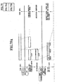
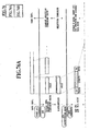
- Fig. 3 illustrates structures of a physical channel
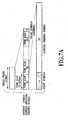
- Figs. 4A and 4B illustrate characteristics of individual physical channels.
- TABLE 4 Characteristics of physical channels Perch channels Common control physical channel Dedicated physical channel Symbol rate 16ksps Reverse direction: 16/64 ksps Forward direction: 64 ksps 32/64/128 /256/512/1024 ksps Characteristics Transmission power control is not applied. Usually, there are a first perch channel through which transmission is always carried out, and a second perch channel through which only parts of symbols are transmitted. *Only radio frames containing transmitted information are sent. No symbols including pilot symbols are sent of radio frames without containing transmitted information. (PD sections of PCH are always sent). *High speed closed loop transmission power control is not carried out. High speed closed loop transmission power control can be carried out.
- a perch channel is a physical channel whose receiving level is measured for selecting a cell of a mobile station. Besides, the channel is a physical channel which is initially captured when the mobile station is turned on.
- the perch channel includes a first perch channel and a second perch channel: The former is spread by a short code uniquely assigned to the system for accelerating the cell selection when the mobile station is turned on, and continues transmission all the time; whereas the latter is spread by a short code corresponding to a forward long code, and transmits only part of symbols.
- the perch channel is a one-way physical channel from the base station to mobile stations.
- the short codes used by the second perch channel differ from the short code system employed by the other physical channels.
- the common control physical channel is used in common by multiple mobile stations located in the same sector.
- the reverse common control physical channel is a random access channel.
- Dedicated physical channels are each established between a mobile station and the base station in a point-to-point fashion.
- Figs. 4A and 4B illustrate the signal formats of channels other than the reverse common control physical channels.
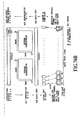
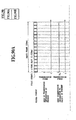
- Figs. 5 and 6 illustrate simulation results of the effect of varying the number of pilot symbols for respective symbol rates: simulation results with respect to the physical channels with different symbol rates of 32 ksps (symbols per second) and 128 ksps, respectively.
- the horizontal axis represents the number of pilot symbols contained in each time slot (of 0.625 msec)
- the vertical axis represents a necessary Eb/Io, that is, a ratio of the required received power (Eb) per bit after the error correction to the interference power (Io) per unit frequency band in a state that meets a quality required.
- the Eb is obtained by dividing the total amount of the received power by the number of bits after the error correction, in the case of which overheads such as the pilot symbols are counted as part of the received power.
- the radio wave propagation conditions are identical in two Figs. 5 and 6.
- an optimum value of the number of pilot symbols that can maximize the capacity is present because there is a trade-off between the degradation in the accuracy of the coherent detection due to the reduction in the number of pilot symbols, and the increase in the overhead due to the increase in the number of pilot symbols.
- the optimum number of the pilot symbols varies depending on the symbol rates, such as six for 32 ksps and 16 for 128 ksps.
- the ratio of the optimum number of the pilot symbols to the total number of symbols also vary depending on the symbol rate such as 30% for 32 ksps and 20% for 128 ksps.
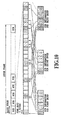
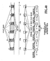
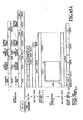
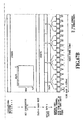
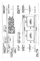
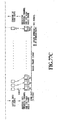
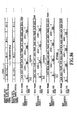
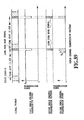
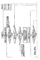
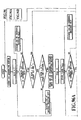
- Figs. 7A and 7B illustrate the signal formats of the radio frame and time slots of the reverse common control physical channel, in which the numerals designate the number of symbols.
- the super frame consists of 64 radio frames, and is determined on the basis of SFN which will be described below.
- the pilot symbols are transmitted together with the sync words. This makes it possible to reduce the overhead and increase the data transmission efficiency.
- the sync words can be considered as an integral part of a known fixed pattern, and are utilized as the part of the pilot symbols for the coherent detection, the accuracy of the coherent detection can be maintained without the slightest degradation.
- burst mode transmission of a radio frame length can take place, in which case, the pilot symbols are added at the final position of the bursts.
- the number of symbols and the symbol pattern to be added is the slot #1 pattern of Table 5.
- one radio frame forms one burst, and the pilot symbols are added at the final position of the radio frame.
- the number of symbols and the symbol pattern to be added is the slot #1 pattern of Table 5. 4.1.2.3.3. TPC symbol.
- TPC symbol transmission power control amount 1 + 1. 0 d B 00 - 1. 0 d B
- the perch channels use two spreading codes to transmit their long code mask symbols individually.
- the second perch channel transmits only the long code mask symbol without transmitting any other symbol.
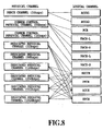
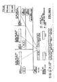
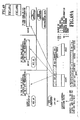
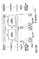
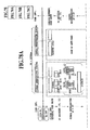
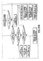
- Fig. 8 illustrates the relationships between the physical channels and the logical channels that are mapped onto the physical channels.
- Fig. 9 illustrates a mapping example of the logical channel onto the perch channel.
- BCCH1 Onto the initial position of the super frame, BCCH1 is mapped without exception.
- BCCH1 or BCCH2 is mapped in accordance with structure information designated.
- the BCCH1 and BCCH2 are each transmitted in every 2 XN consecutive radio frames so that two radio frames constitute one radio unit, and transmit one layer 3 message.
- the layer 3 message transmitted through the BCCH1 and BCCH2 do not overlay two or more super frames.
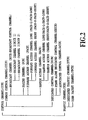
- the BCCH1 and BCCH2 each transmit in each radio unit the following information, for example, which is generated by the BTS.
- the reverse interfering power amount is a time-varying latest result measured by the BTS.
- the information BCCH1 and BCCH2 transmit can have different characteristics.
- BCCH1 can transmit time-fixed information
- BCCH2 can transmit time-varying information.
- the time-varying information can be transmitted efficiently by reducing the occurrence frequency of the BCCH1 and increasing that of the BCCH2.
- the occurrence frequencies of the BCCH1 and BCCH2 can be determined considering the frequency of changes in the information. It is also possible to dispose the BCCH1 at fixed positions of the super frame, such as the initial and central positions, for example, and places BCCH2 at the remaining positions.
- time-fixed information there are code numbers of control channels of contiguous cells or the present cell.
- the above-mentioned reverse interfering power amount is time-varying information.
- BCCH1 and BCCH2 are broadcast control channels
- BCCH1 and BCCH2 are broadcast control channels.
- These multiple broadcast control channels can be transmitted with varying their occurrence frequencies.
- One forward common control physical channel into which the FACHs are mapped is paired with one reverse common control physical channel.
- the pair is designated by a pair of spreading codes.
- the designation of the pair is in terms of the physical channel, in which the sizes (S/L) of the FACH and RACH are not defined.
- As the FACH a mobile station receives and the RACH it transmits a pair of the FACH and RACH is used on the pair of the forward common control physical channel and reverse common control physical channel, respectively.
- the Ack is transmitted through the FACH-S on the forward common control physical channel which is paired with the reverse common control physical channel through which the received RACH is transmitted.
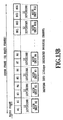
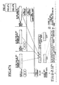
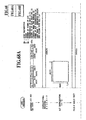
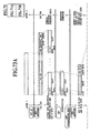
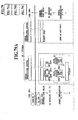
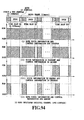
- Fig. 10 illustrates a mapping method of the PCHs.
- the PCHs are each divided into a plurality of groups in a super frame, and each group transmits the layer 3 information.
- Each group of the PCHs contains information of an amount of four time slots, and consists of six information portions: two portions are for incoming call presence and absence indicators (PD portions), and the remaining four portions are for called user identification number portions (I portions).
- PD portions incoming call presence and absence indicators
- I portions user identification number portions
- the six information portions are assigned to over 24 time slots in a predetermined pattern in all the groups.
- the pattern over the 24 time slots are shifted every four slot interval so as to dispose the plurality of groups onto the single common control physical channel.
- the first PCH is disposed such that the initial symbols of the PD portion of the first PCH becomes the initial symbols of the super frame.
- the sections of PCHs in each group are disposed in the PCH radio frames such that they are shifted every four time slot interval in the order of the second group, third group, etc.
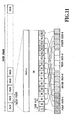
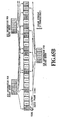
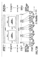
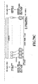
- Fig. 11 shows a mapping example of the FACH.
- Any FACH radio frame on a common control physical channel can be used as either a logical channel FACH-L or FACH-S.
- the logical channel that receives a transmission request first is transmitted by the FACH radio frame.
- FACH-L is used, and otherwise FACH-S is used.
- FACH-S *With respect to FACH-S, four FACH-S'es are time multiplexed into one FACH radio frame to be transmitted.
- Each of the four FACH-S'es consists of four time slots, and is disposed in one radio frame at every four time slot interval, with shifting one slot for each FACH-S.
- the time slots assigned to the four FACH-S'es are as follows.
- First FACH-S First, fifth, ninth and 13th time slots.
- Second FACH-S Second, sixth, 10th and 14th time slots.
- Third FACH-S Third, seventh, 11th and 15th time slots.
- FACH-S If the first logical channel that receives the transmission request is a FACH-S, other FACH-S'es that are stored in a buffer at that time can be transmitted up to four with time multiplexing them into one FACH radio frame. In this case, even if a FACH-L has been stored by that time, FACH-S'es that receive a transmission request later than that FACH-L can be multiplexed and transmitted.
- a mobile station can simultaneously receive the entire FACH-S'es and FACH-L on each common control physical channel. It is sufficient for a mobile station to receive one common control physical channel even in the case where a base station transmits a plurality of common control physical channels for transmitting FACHs. Which one of them is to be received by the mobile station is determined between the mobile station and the BTS.
- the FACH-S has two modes of transmission format. One is a format (layer 3 transmission mode) for transmitting information of layer 3 and higher order which is designated. The other one is a format (ACK mode) for transmitting an ACK of receiving a RACH.
- An ACK mode FACH-S can contain ACKs to up to seven mobile stations at the maximum.
- FACH-L's or FACH-S'es are used, without being used in a mixed manner.
- the (n+1)-th FACH-S radio unit follows the n-th FACH-S radio unit, except that it is the first FACH-S radio unit that follows the fourth FACH-S radio unit.
- RACH-S is mapped onto a 16 ksps reverse common control physical channel
- a RACH-L is mapped onto a 64 ksps reverse common control physical channel.
- Both the RACH-S and RACH-L consist of one radio frame of 10 ms long. When they are transmitted through wireless sections, four pilot symbols are added to the final position of the radio frame.
- a mobile station uses the RACH-L or RACH-S freely in accordance with a transmission information volume.
- a base station transmits Ack to the mobile station through a FACH.
- the RACH and its associated FACH that transmits the Ack are designated by assigning the same RL-ID to both the channels.
- the frame timing for transmitting the RACH from the mobile station is delayed by a predetermined offset from the frame timing of the common control physical channel onto which the FACH for transmitting the Ack is mapped.
- the offset can take 16 values, one of which the mobile station randomly selects to send the RACH.
- the base station must have the function of receiving the RACH-L and RACH-S at all the offset timings.
- a DTCH and an ACCH are time multiplexed to share the same dedicated physical channel.
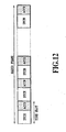
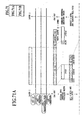
- Fig. 12 illustrates a mapping method of the DTCH and ACCH onto the dedicated physical channel.
- the number of radio frames constituting a radio unit of the ACCH varies depending on the symbol rate of a dedicated physical channel.
- the radio unit of the ACCH is allocated in synchronism with a super frame such that it is divided in accordance with the number of the time slots and its divisions are allocated to the entire time slots over one or more radio frames.
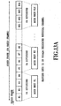
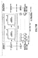
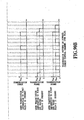
- Figs. 13A-13C each illustrate a mapping method of the ACCH onto a super frame of the dedicated physical channel for each symbol rate.
- the ACCH radio unit does not overlay two or more physical channels, but is transmitted using a particular one code (physical channel).
- the particular one code is predetermined.
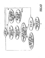
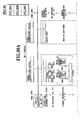
- Figs. 64-84 illustrate coding processings of logical channels, which are carried out in a base station (BTS).
- BTS base station
- An error detecting code is added to each CPSPDU (common part sublayer protocol data unit), each internal encoding unit, or each selection combining unit.
- FIG. 64-84 illustrate by shaded portions the CRC calculation application range and CRC bits.
- a PAD is used for aligning the length of the CPSPDU with the integer multiple of the internal encoding unit length or selection combining unit length.
- *Length shows an information volume (the number of octets) of the padding in the CPSPDU.
- *W bits indicates the initial, continuous, or final position of the CPSPDU for each internal encoding unit (for each selection combining unit in the case of an ACCH).
- Table 7 The relationships between the bit patterns of the W bits and their indications are shown in Table 7, and the uses thereof is shown in Fig. 14.
- FIGs. 15A and 15B each shows a convolutional encoder.
- the output of the convolutional encoder is produced in the order of output 0, output 1 and output 2 (coding rate of 1/2 is applied to up to output 1).
- the depth of the interleaving is 36 symbols independently of the symbol rate of the DTCH.
- Each external code handling unit consists of 80 ms long data.
- the external code handling is processed in synchronism with radio frames.
- the radio frames in the external code handling unit are provided with sequence numbers 0-7 in the order of transmission.
- the external code handling alignment is established in accordance with the sequence numbers.
- *It is the latest measured value of the reverse interfering amount (total received power including thermal noise) for each sector.
- *Table 9 shows an example of correspondence between bit values and reverse interfering amounts. The bits are transmitted from the leftmost bit in the table.
- Bit values Reverse interfering amounts 1 1 1 1 1 1 1 equal to or greater than - 1 4 3. 0 d B m/H z 1 1 1 1 1 0 . . . . equal to or greater than - 1 4 3. 5 d B m/H z less than - 1 4 3 . 0 d B m/H z . . . . 0 0 0 0 1 equal to or greater than - 1 7 4. 0 d B m/H z less than - 1 7 3. 5 d B m/H z 0 0 0 0 0 less than-174. 0 d B m/H z
- the SFN has a one-to-one correspondence with the radio frame, and is incremented by one for each 10 msec long radio frame.
- Fig. 16 illustrates a transmission example of the SFN.
- the base station generates counter values based on the timings designated by transmission paths.
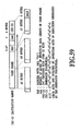
- Fig. 17 shows the bit arrangement of the SFN. The bits are transmitted from the MSB of this figure.
- a PID is an identifier for identifying, on a common control physical channel, a call or a mobile station, which is associated with transmitted information.
- the PID value on a FACH is designated together with its transmitted information.
- the PID value transmitted over the RACH is notified along with the transmitted information.
- a range over 16 bits is divided into two parts which are used for the foregoing purposes.
- Table 10 shows an example of the ranges for the uses.
- PID values (0 - 65535) are represented by the 16-bit binary notation. The bits are transmitted from the MSB. Table 10 Range of PID values. Uses Range of values SDCCH establishment request immediately before SDCCH establishment and establishment response 0 ⁇ 6 3 Packet transmission 6 4 ⁇ 6 5 5 3 5
- *Mo is a bit for identifying the mode of the FACH-S.
- the U/C bit is an identifier for identifying whether the information conveyed by the CPSSDU (content provider system service data unit) is user information or control information.
- Table 12 Structure of U/C bit Bit Identification content 0 User information 1 Control information
- the TN bit is an identifier for identifying a base station side terminal node of the information conveyed by the CPSSDU.
- Table 13 Structure of TN bit Bit Identification content RACH, Reverse UPCH FACH, Forward UPCH 0 MCC termination Transmission from MCC 1 BTS termination Transmission from BTS
- the sequence number is for achieving highly efficient assembling of CPS considering retransmission (layer 1 retransmission) over the RACH between the MS and BTS.
- Figs. 96A and 96B illustrate a flowchart of an assembling method of CPSPDU of a RACH using the W bits and S bits.
- the PD portion includes PD1 and PD2, both of which can be used in the same manner.
- the PD portion is an identifier for instructing a mobile station about the presence and absence of incoming call information, and the necessity of receiving the BCCH. Transmitting the PD1 and PD2 at different timings enables the mobile station to improve the reception quality owing to the time diversity effect.
- Table 14 Bit structure of PD portion. Bits Identification contents all 0s Incoming call information is absent and BCCH reception is unnecessary. all 1s Incoming call information is present or BCCH reception is necessary.
- the maximum length of the CPSSDU is LCPS regardless of the types of the logical channels.
- the LCPS is set as one of the system parameters.
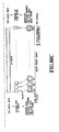
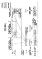
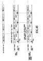
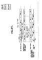
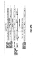
- Figs. 85-88 illustrate concrete examples of the transmitting and receiving timings of radio frames along with long code phases for each physical channel, when the chip rate is 4.096 Mcps.
- the BTS generates a reference frame timing (BTS reference SFN) from a transmission path.
- BTS reference SFN reference frame timing
- the transmitting and receiving timings of various physical channels are established as timings that are offset from the BTS reference SFN.
- Table 15 shows the offset values of the radio frame transmitting and receiving timings of the physical channels.
- the physical channels other than the perch channel are not provided with the SFN, all the physical channels consider the frame number (FN) corresponding to the SFN of the perch channel.
- the FN which is not present physically in a transmitted signal, is generated in a mobile station and the base station for respective physical channels in accordance with the predetermined correspondence with the SFN of the perch channel. The correspondence between the SFN and FN are also shown in Figs. 85-88.
- T SECT s vary from sector to sector. (Although they are synchronized between sectors within the base station, they are asynchronous between base stations).
- a mobile station can recognize, if it receives the long code mask symbol, the long code phase (corresponding to T SECT ), and hence can carry out transmission and reception using it.
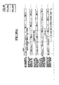
- Each T CCCH is an offset value for a radio frame timing of the common control physical channel.
- *It can be set for each common control physical channel.
- the T FRAME is an offset value for the radio frame timing of the dedicated physical channel.
- *It can be set separately for each dedicated physical channel.
- the base station determines the T FRAME at a call setup, and notifies the mobile station of it.
- the reverse link transmission is also carried out using this offset value.
- *It serves for the purpose of making uniform (random) the transmission traffic, thereby improving the efficiency of wire ATM transmission.
- *Its value is represented in terms of slots (0.625 ms), and its range is within one radio frame.
- T SLOT is an offset value for the radio frame timing of the dedicated physical channel.
- *It can be set separately for each dedicated physical channel.
- *It serves to prevent the transmission pattern matching, and thereby making the interference uniform.
- T DHO is an offset value for the radio frame timing of the dedicated physical channel and for the reverse link long code phase.
- *It corresponds to a measured value by a mobile station of the timing difference between the reverse direction transmitting timing of the mobile station and the received timing by the mobile station of the perch channel of the DHO destination station.
- the radio frame timing of the dedicated physical channel of a reverse link is delayed by half a slot interval as compared with that of a forward link.
- the delay of the transmission power control becomes one slot interval, thereby reducing control errors.
- More specific setting scheme of the timing differences are illustrated in Figs. 85-88.
- the radio frame timing of the RACH is offset from that of the corresponding forward common control physical channel.
- the offset value has four steps at time slot intervals.
- the initial position of a radio frame is aligned with the initial value of the long code phase.
- the long code phase has four offset values, as well.
- a mobile station can transmit by selecting any one of the four offset timings.
- the BTS can always receive the RACHs simultaneously which are transmitted at all the offset timings.
- a forward long code consists of the Gold codes using M sequences obtained from the following generator polynomials. (Shift register 1) X 18 + X 7 + 1 (Shift register 2) X 18 + X 10 + X 7 + X 5 + 1
- the initial state of a long code number value is defined as a state in which the value of the shift register 1 represents that long code number, and the value of the shift register 2 is set at "all 1s".
- the range of the long code number is 00000h - 3FFFFh.
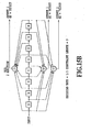
- the MSB of the long code number is first input to the leftmost bit of the shift register 1 of the generator of Fig. 18.
- the forward long code has a period of one radio frame interval. Accordingly, the output of the long code generator is truncated at 10 ms so that it repeats the pattern from phase 0 to the phase corresponding to 10 ms. Thus, the range of the phase varies as shown in Table 16 in accordance with the chip rate. In addition, as will be described later in 4.1.5.3., the phase of the inphase component of the long code is shifted from that of the quadrature component by an amount of "shift", which makes it possible to differentiate the inphase component from the quadrature component. Table 16 shows the phases of the two components when the "shift" is set at 1024.
- the long code generator can implement a state in which its phase is shifted from the initial state by an amount of any integer multiple of a clock period.
- Table 16 Correspondence between chip rates and ranges of the phase of a forward long code.
- Chip rates (Mcps) Ranges of the phase (chips) Inphase component Quadrature 1.024 0 ⁇ 10239 1024 ⁇ 11263 4.096 0 ⁇ 40959 1024 ⁇ 41983 8.192 0 ⁇ 81919 1024 ⁇ 82943 16.384 0 ⁇ 163839 1024 ⁇ 164863
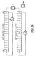
- a reverse long code is one of the Gold codes using M sequences obtained from the following generator polynomials. (Shift register 1) X 41 + X 3 + 1 (Shift register 2) X 41 + X 20 + 1
- the initial state of a long code number is defined as a state in which the value of the shift register 1 equals that long code number, and the value of the shift register 2 is set at "all 1s".
- the range of the long code number is 00000000000h - 1FFFFFFFFh.
- the MSB of the long code number is first input to the leftmost bit of the shift register 1 of the generator of Fig. 19.
- the reverse long code has a period of 216 radio frame intervals (that is, 210 super frame intervals). Accordingly, the output of the long code generator is truncated at 2 16 radio frame intervals so that it repeats the pattern from phase 0 to the phase corresponding to 2 16 radio frame intervals. Thus, the range of the phase varies as shown in Table 17 in accordance with the chip rate. In addition, as will be described later in 4.1.5.3., the phase of the inphase component of the long code is shifted from that of the quadrature component by an amount of "shift". Table 17 shows the phases of the two components when the "shift" is set at 1024.
- Chip rates (Mcps) Ranges of the phase (chips) Inphase component 1.024 0 ⁇ 2 16 ⁇ 10240-1 1024 ⁇ 2 16 ⁇ 10240+ 1023 4.096 0 ⁇ 2 16 ⁇ 40960-1 1024 ⁇ 2 16 ⁇ 40960+ 1023 8.192 0 ⁇ 2 16 ⁇ 81920-1 1024 ⁇ 2 16 ⁇ 81920+1023 16.384 0 ⁇ 2 16 ⁇ 163840-1 1024 ⁇ 2 16 ⁇ 163840+1023
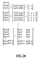
- a short code consisting of the layered orthogonal code sequences is designated by a code class number (Class) and a code number (Number). The period of the short code varies for each short code class number.
- FIG. 20 illustrates a generating method of the short codes which are each represented as C Class (Number).
- the period of the short codes equals the period of a symbol. Therefore, if the chip rate (spread spectrum bandwidth) is the same, the short code period varies in accordance with the symbol rate, and the number of usable short codes also varies in accordance with the symbol rate.
- the relationships of the symbol rate with the short code class, short code period and short code number are shown in Table 18.
- the short code numbering system is composed of the code class and code number, which are represented by 4 bits and 12 bits in the binary notation, respectively.
- the short code phase is synchronized with the modulation and demodulation symbols.
- Fig. 21 shows a configuration of a short code generator for the long code mask symbols.
- the initial value of the shift register 1 is a short code number N LMS (value range: 0-255) for the long code mask symbol.
- the MSB of the number N LMS is first input in the leftmost bit of the shift register 1.
- the period of the short code is one symbol interval (256 chips) of the perch channel.
- a long code number is allocated to each reverse link physical channel.
- the long code number is designated.
- Dedicated physical channels into which the TCH, ACCH and UPCH are mapped use the reverse link long code allocated to each mobile station.
- Dedicated physical channels, into which the other logical channels are mapped, and a common physical channel use the reverse link long code allocated to each base station.
- a short code number for symbols on the first perch channel other than the long code mask symbols is common to all the cells, which is C 8 (0). (However, any short code designated is usable for the first perch channel).
- N LMS 1 (However, any short code number N LMS designated for the long code mask symbol is usable for the long code mask symbol of the first perch channel).
- As a short code number for long code mask symbol of the second perch channel one of the short codes that are assigned to the system in advance is used for each sector.
- the short code numbers of these short codes are stored in the BSC (base station control center) and mobile stations. (However, any short code for the long code mask symbol designated is usable for the second perch channel).
- the short code number for the long code mask symbol of the second perch channel has one to many correspondence with the forward long codes used in the same sector. Examples of the correspondence are shown in Table 19. The correspondence is stored in the BSC and mobile stations. (However, any short code for the long code mask symbol and any forward long codes which are designated for the second perch channel are usable in the same sector). Table 19 Examples of the correspondence of the short codes for the second perch channel with the forward link long codes.
- Short code numbers N TPC for long code mask symbols on the second perch channel Forward long codes 2 0 0 0 0 1 h ⁇ 0 0 0 2 0 h 3 0 0 0 2 1 h ⁇ 0 0 0 4 0 h 4 0 0 0 4 1 h ⁇ 0 0 0 6 0 h 5 0 0 0 6 1 h ⁇ 0 0 0 8 0 h
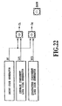
- Fig. 22 illustrates a generating method of an inphase spreading code Ci and a quadrature spreading code Cq using a long code and short code.
- Fig. 23 shows a configuration of a spreader for generating the inphase component Si and quadrature component Sq of a spread signal by spreading the inphase component Di and quadrature component Dq of the transmitted data with the spreading codes Ci and Cq.
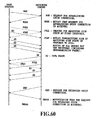
- FIG. 24 illustrates a random access transmission scheme
- a mobile station transmits a RACH at a timing which are randomly delayed from the received frame timing of the forward common control channel.
- the random delay amount is one of the 16 offset timings as shown in Figs. 85-88.
- the mobile station randomly selects one of the offset timings each time it sends the RACH.
- the base station transmits, using the ACK mode of the FACH-S, the PID of that RACH in the FACH radio frame following the FACH radio frame that is being transmitted at the detection timing of the RACH.
- the mobile station transmits, after receiving the ACK for the current radio frame over the ACK mode FACH-S, the next radio frame, in the case where multiple RACH radio frames to be transmitted are present.
- the mobile station uses, when one piece of CPS information to be transmitted consists of a plurality of RACH radio units, the same PID value for all these RACH radio units. In addition, it uses one of the RACH-L and RACH-S, inhibiting mixed use of them for the transmission of the one piece of the CPS information.
- the mobile station retransmits the RACH in a case where it cannot receive over the ACK mode FACH-S the PID value of the RACH it transmitted even if TRA msec has passed after the transmission of the RACH. In this case, it uses the same PID value.
- the maximum number of retransmissions is NRA (Thus, the same RACH radio unit can be transmitted NRA+1 times at the maximum including the first transmission).
- the ACK mode of the FACH-S can contain up to seven PIDs of the RACHs with which the detection result of the CRC is correct.
- the base station transmits the ACK mode FACH-S over the first FACH in the order of received timings of the RACHs with which the CRC is correct.
- those RACHs with which TACK msec has elapsed after detecting the correct CRC are excluded from those to be transmitted over the ACK mode FACH-S.
- the multicode transmission is carried out as follows when a designated single RL-ID consists of a plurality of dedicated physical channels (spreading codes), so that the pilot coherent detection and transmission power control are carried out in common to all the dedicated physical channels in the single RL-ID.
- the pilot coherent detection and transmission power control are carried out for each RL-ID.
- the pilot symbols and TPC symbol are transmitted through one of the plurality of dedicated physical channels in the single RL-ID.
- the pilot symbols and TPC symbol are transmitted through that one dedicated physical channel at the transmission power a few times greater than the transmission power at which symbols other than the pilot symbols and TPC symbol are transmitted through the dedicated physical channels in the RL-ID.
- the amplitude ratio of the transmission power of the pilot symbols and TPC symbol (pilot portion) to that of the data symbol section (data portion) has an optimum value in terms of capacity that minimizes Eb/Io. This is because there is a tradeoff between the fact that the channel estimation accuracy is degraded when the amplitude of the pilot portion is reduced, and the fact that the overhead is increased when the amplitude of the pilot portion is increased.
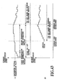
- Fig. 26 illustrates a simulation result of the optimum value estimation of the amplitude ratio of the two transmission powers.
- the horizontal axis represents the ratio of the amplitude (AP) of the transmitted wave of the pilot portion to the amplitude (AD) of the transmitted wave of the data portion, which are designated in Fig. 25 by AP and AD, respectively (in Fig. 25, they are represented as the squares AP 2 and AD 2 of the amplitudes because the vertical axis of Fig. 25 represents the transmission power).
- the vertical axis of Fig. 26 represents the required Eb/Io as in Figs. 5 and 6.
- the simulation result in Fig. 26 shows that the optimum value in terms of capacity is obtained when the amplitude AP is twice the amplitude AD.
- the optimum transmission power ratio is obtained when the transmission power of the pilot portion is 4/3 times that of the data portion.
- the transmission power ratio between the pilot portion and the data portion is made variable.
- pilot portions are added in the same phase when they are spread by the same short code, achieving the same effect as when the transmission is carried out with increased transmission power.
- Figs. 89-94 show transmission patterns of the respective physical channels.
- the first perch channel is transmitted continuously at designated transmission power PP1 except for the long code mask symbol contained in each time slot.
- the long code mask symbol contained in each time slot is transmitted at the transmission power lower than PP1 by a designated value Pdown.
- the first perch channel is always transmitted in the above-mentioned method regardless of the presence or absence of the transmission information of the BCCH1 and BCCH2 which are mapped into the first perch channel. If the transmission information is not present, an idle pattern (PN pattern) is transmitted.
- PN pattern an idle pattern
- the long code mask symbol of the second perch channel is transmitted at the same time as the long code mask symbol of the first perch channel.
- the transmission power is a designated value PP2, which is invariable.
- the values PP1, Pdown and PP2 are determined such that mobile stations located in contiguous sectors can make a sector identification.
- FACHs Forward common control physical channels
- the transmission power level can be designated for each transmission information, which means that the transmission power level is variable from radio frame to radio frame, although it is fixed at the transmission power value PFL within each radio frame.
- the transmission power value is designated for each transmission information in "Normal mode" FACHs, which means that transmission power levels PFS1-PFS4 are variable from FACH-S to FACH-S in the radio frame.
- the radio frame is transmitted over its entire period.
- the transmission power is variable for each FACH-S.
- the transmission power of the "Ack mode" FACH-S is fixed at a designated transmission power PACK.
- the transmission power of the pilot symbols in the second time slot (that is, the pilot symbols adjacent to the first time slot) is placed at the level equal to the higher transmission power of the two time slots.
- the values PFL, PFS1-PFS4 are determined in accordance with the received SIR of the perch channel in a mobile station, which is included in the RACH.
- the transmission power is designated at a transmission power level PPCH.
- pilot symbols are transmitted together with the PD portion of the time slot into which the PD portion is mapped, although the pilot symbols in the subsequent time slot are not transmitted.
- the I portion of each group is divided into four time slots (I1-I4), and only I portion of a group that contains incoming call information is transmitted. The I portions of the remaining groups without any incoming call information are not transmitted.
- the transmission power is designated at a transmission power level PPCH.
- the time slot, into which the I portion of the group including the incoming call information is mapped, is handled such that the pilot symbols are transmitted at both sides of the symbols for the logical channel without exception. Accordingly, if a time slot associated with the I portion of a group including incoming call information is followed by a time slot associated with the I portion of a group that does not bear any incoming call information, the latter time slot must send pilot symbols.
- the PPCH value is determined such that almost all the mobile stations in the sector can receive.
- RACHs Reverse common control physical channels
- a reverse common control physical channel is transmitted from a mobile station only when transmission information takes place. It is transmitted on each radio frame unit basis.
- the transmission powers PRL and PRS of the RACH-L and RACH-S are determined by the mobile station in an open-loop system, and are fixed within a radio frame.
- pilot symbols are added to be transmitted.
- the transmission power of the pilot symbols is the same as that of the preceding radio frame.
- the transmission power control of the forward dedicated physical channel is carried out, regardless of the originating or terminating call connection or of the diversity handover, such that the transmission is started at a designated transmission power value PD during the initial set of the forward dedicated physical channel, and the transmission power is incremented at fixed intervals until the communication power level reaches a value PD. After that, the transmission power is further incremented at fixed intervals until the receiving synchronization of the reverse dedicated physical channel is established (see 5.2.1.2.2., for details). Until the receiving synchronization of the reverse dedicated physical channel has been established, and the decoding of the reverse TPC symbols becomes possible, the transmission is carried out continuously at the fixed transmission power PD.
- the value PD is determined in the same method as that of the FACH.
- the transmission power is controlled at a control step of 1 dB at every time slot interval in accordance with the decoded result of the TPC symbols.
- the transmission power control method of the forward dedicated physical channel see 5.2.1.1.
- a mobile station starts transmission of a reverse dedicated physical channel, after a receiving synchronization establishing process of the forward dedicated physical channel meets predetermined conditions.
- the transmission power level of the first time slot at the beginning of the transmission is determined in the open loop system as in the RACH, and the subsequent transmission power level of the time slots is determined by the high speed closed loop transmission power control in accordance with the decoded result of the TPC symbols in the forward dedicated physical channel.
- the transmission power is controlled from time slot to time slot by the high speed closed loop transmission power control during the diversity handover.
- the transmission power control method of the reverse dedicated physical channel see 5.2.1.1.
- the DTX control is applied only to the dedicated physical channels.
- the DTX control is carried out on a radio frame (10 msec) basis.
- the DTX is not carried out in the dedicated physical channels (equal to or greater than 64 ksps) for data transmission. They are always in a transmission ON state.
- Table 20 shows methods of making decisions as to whether or not the voice information and the control information are present. Table 20 Methods of deciding the presence and absence of voice information and control information Information type Information is present Information is absent Voice information CRC on a DTCH selection combining unit basis is correct; or a power ratio of the average received power of the pilot and TPC symbols to the average received power of the DTCH symbols is equal to or more than P DTX dB. CRC on a DTCH selection combining unit basis is incorrect; and a power ratio of the average received power of the pilot and TPC symbols to the average received power of the DTCH symbols is equal to or less than P DTX dB. Control information CRC on an ACCH selection combining unit basis is correct. CRC on an ACCH selection combining unit basis is incorrect.
- the average received power of the symbols in Table 20 is the average value of the received power of all the associated symbols in the radio frame.
- the transmission of symbols for the SDCCH is made ON when control information to be transmitted is present, and made OFF when no control information is present.
- the DTX control is carried out on a radio frame (10 msec) basis.
- *A receiving side carries out the processing in accordance with the CPS-PDU assembling method as illustrated in Figs. 95A and 95B. It is not necessary to make a decision as to whether the control information is present or not.
- the BTS has three modes about the pilot symbols and TPC symbol. The modes are designated.
- the need for transmission is decided for each radio frame.
- the transmission of the entire pilot symbols and TPC symbol in a radio frame is halted if both the following conditions 1 and 2 are satisfied.
- the transmission of the entire pilot symbols and TPC symbol in the radio frame is restarted if the following condition 3 or 4 is detected.
- Condition 1 FNDATA or more radio frames have passed after the control information or user information to be transmitted is completed.
- Condition 2 Incorrect CRC results of received radio frames are continuously detected for FCRC or more radio frames.
- Condition 3 Control information or user information to be transmitted takes place.
- Condition 4 A correct CRC result of a received radio frame is detected.
- a mobile station decides the transmission ON/OFF of the pilot symbols and TPC symbol using the presence and absence of the control information or user information to be transmitted in connection with the detection result of an out-of-sync.
- radio frames into which an idle pattern is inserted in advance are sent by FIDL frames, followed by the transmission of a radio frame into which the control information or user information to be transmitted is inserted.
- the pilot symbols and TPC symbol are also transmitted in the radio frames into which the idle pattern is inserted.
- the pilot symbols and TPC symbol are transmitted in part of the slots.
- the high speed closed loop transmission power control follows only the TPC symbols from the mobile station which are determined in accordance with the pilot symbols and TPC symbols the BTS transmits, and ignores the TPC symbols from the mobile station which are determined in accordance with the pilot symbols and TPC symbols the BTS does not transmit. Therefore, the transmission power control intervals vary depending on the P freq values.
- the power ratio of the transmission power (Pon) while the transmission is ON to the transmission power (Poff) while the transmission is OFF meets the transmission ON/OFF ratio of the transmission characteristics defined in 5.1.1.
- the DTX control is carried out on a radio frame (10 msec) basis.
- the idle pattern is inserted into the entire CRC encoded fields (shadowed portions in Figs. 64A, 64B, 84A and 84B) on a selection combining unit or internal encoding unit basis. These fields include the CRC checking bits, as well.
- the idle pattern consists of any PN pattern, and the same pattern is used in common to all the internal encoding units or selection combining units of each logical channel. In addition, the idle pattern is arranged such that it causes an incorrect CRC result when no error takes place in the received side.
- BTS base station
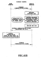
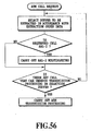
- Mobile stations are divided into groups in a predetermined manner, and are subject to paging on a group by group basis.
- the BTS carries out the grouping, and designates the corresponding group number using the paging information containing the identification number of a called mobile station.
- the BTS transmits the paging information using the I portions (I1-I4) of the PCH of the designated group number.
- the BTS places "all 0s" in the two PD portions (PD1 and PD2) in the PCHs of the groups having no paging information, and transmits them without transmitting the I portion.
- the BTS places "all 1s" in the PD1 and PD2 of the PCH associated with the designated group number, and transmits the designated paging information using the I portion of the same PCH.
- a mobile station usually receives only the 8-bit PD1. It carries out coherent detection using the pilot symbols (four symbols) immediately previous to the PD1.
- the mobile station carries out a majority decision processing (soft decision). It is assumed that a value computed by the processing takes "0" when the PD portion is all 0s in a state without degradation in the receiving quality, and takes a positive maximum value when it is all 1s.
- the following operations are performed in accordance with the processing result and decided threshold values (M1 and M2, where M1>M2).
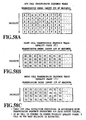
- Figs. 28A and 28B illustrate the mapping into an ATM cell.
- Figs. 29A and 29B illustrate the mapping into an ATM cell
- Fig. 30 shows a pulse mask
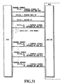
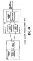
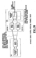
- Fig. 31 shows the link structure between the BTS and MCC.
- Channel numbers are assigned to individual HWYs between the base station and the switching center. The correspondence between the physical HWY interface mounted positions and the channel numbers are fixedly set in advance. The range of the channel numbers is 0-3 for the 1.5M-HWY, and only 0 for 6.3M-HWY.
- VPI The VPI value is only "0", and the VPI is not used substantially.
- VCI 256/VPI.
- VCI 64: Used for timing cell. A minimum channel number for each BTS is used. The following VCIs can be set as the VCIs other than those used for super frame phase correction. In connection with this, the AAL types used in the respective VCIs are also shown.
- the VCIs other than those used for the super frame phase correction are assignable to any channel numbers by any number.
- the correspondence is established between the VCIs other than those used for the super frame phase correction, and the channel numbers and VCI values.
- a method of using the CID value is set.
- the AAL-Type is designated at the time when a wire channel is established.
- Table 22 shows an example of the correspondence between the used transmission information types and the AAL-Types, although the correspondence between them can be set freely.
- Table 22 Example of correspondence between wire channel transmission information types and AAL-Types.
- Transmission information types AAL-Type VCI types DTCH transmission information 2 For transmission signals between MS and MCC ACCH transmission information 2 SDCCH transmission information 2 BCCH1, 2 transmission information 5 For control signals between BTS and MCC PCH transmission information 5 For paging FACH transmission information (for packet transmission) RACH transmission information (for packet transmission) UPCH transmission information 2 For transmission signals between MS and MCC Control signal between BTS and MCC VCI types 5 For control signals between BTS and MCC
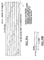
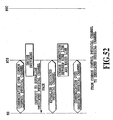
- Fig. 32 shows an idle cell on an ATM channel.
- An idle cell according to ITU-T standard is used.
- AAL-Type 2 is a protocol of an ATM adaptation layer of a composite cell (AAL type 2) which is transmitted over an interface (Super A interface) section between the base station and switching center.
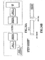
- Figs. 33A and 33B show connecting configuration of AAL-Type 2.
- control for assuring a minimum bandwidth for each quality class is needed to meet the quality of service parameters such as a delay and a cell loss ratio.
- the band assurance is carried out which is assigned to each quality class at a short cell level.
- the short cell quality class falls into the following four classes depending on (a maximum allowable delay time; and a maximum cell loss ratio).
- the transmission order of short cells are determined in accordance with the quality classes, and the required bandwidth is ensured for each quality class.
- a concrete method for ensuring the bandwidth will be described in 5.3.5.
- the transmission information is divided into a plurality of short cells to be transmitted.
- the plurality of short cells are transmitted continuously using the same VCI.
- the continuity is ensured only within the same VCI, but not ensured between different VCIs.
- a standard cell with another VCI can intervene between the short cells to be transmitted.
- AAL-Type 5 as well as AAL-Type 2 is used as the AAL of ATM cells transmitted on the Super A interface between the base station and switching center.
- the SSCOP Service Specific Connection Oriented Protocol
- Figs. 34A and 34B show connecting configuration of AAL-Type 2.
- control for assuring a minimum bandwidth for each quality class is needed to meet the quality of service parameters such as a delay and a cell loss ratio.
- the quality classes are shown below.
- the band assurance is carried out which is assigned to each quality class at a VCI level.
- the quality class falls into the following five classes in accordance with (a maximum allowable delay time; and a maximum cell loss ratio).
- the interrupt buffer cell is given the highest priority (with a minimum delay, inhibiting discarding) to be output.
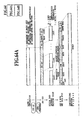
- Fig. 35 illustrates the format of AAL-2.
- CID Channel identifier: 0/PADDING; 1/ANP; 2-7/RESERVED
- PPT CPS-Packet Payload Type: It includes start/continue and end information of the payload.
- UUI CPS-User to User indication.
- the UUI and the plurality of short cells bearing the divided transmission information to be transmitted are continuously transmitted using the same VCI, for the receiving side to be able to assemble the transmission information.
- Fig. 36 shows the format of the SAL.
- Table 23 shows a specifying method of SAL fields.
- Table 24 shows the presence and absence of the uses of the SAL third octet.
- Table 25 shows a specifying conditions of the SAL fields.
- BER BER degradation detection 1 Detect degradation. 0: Normal. Level Level degradation detection 1: Detect degradation. 0: Normal.
- CRC CRC checking result 1 NG. 0: OK.
- SIR Received SIR 0-15 Received SIR increases with the value RCN (radio channel number) Radio channel number 0-15: Radio channel sequence number RSCN (radio subchannel number) Radio subchannel number 0-15: Radio subchannel sequence number Table 24 The used state of the SAL third octet.
- RCN radio channel number
- RSCN radio subchannel number
- Table 24 The used state of the SAL third octet.
- Frame in radio channel is not divided. Both RCN (radio channel number) and RSCN (radio subchannel number) are unused. Only RCN is used. Frame in radio channel is divided. Only RSCN is used. Both RCN and RSCN are used.
- the division of the radio channel frame is carried out when 128 kbps or more unrestricted digital service is provided, and 256 ksps or more dedicated physical channel is used.
- the unit of division is the unit, on the basis of which the external encoding at a user information rate of 64 kbps (1B) is carried out. See, Figs. 78A-80C.
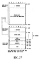
- Fig. 37 shows a format of an AAL-5 cell. To the LAST cell, a PAD and CPCS-PDU trailer are added. *PAD (CPCS padding)
- CPCS-UU CPCS user to user indicator. It is used for transparently transferring information used in a higher layer.
- CPI Common part type indicator. Uses are not yet defined. All “0s" are set at the present.
- LENGTH CPCS-PDU payload length. It indicates a user information length in byte.
- CRC Cyclic redundancy code. It is used for detecting errors of the entire CPCS frame.
- the generator polynomial X 32 + X 26 + X 23 + X 22 + X 16 + X 12 + X 11 + X 10 + X 8 + X 7 + X 5 + X 4 + X 2 + X + 1. 4.2.3.3. Timing cell.
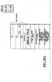
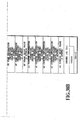
- Figs. 38A and 38B illustrate a signal format of a timing cell that is used for a SFN (System Frame Number) synchronization establishing processing when starting the BTS.
- Table 26 shows a method of specifying information elements in the signal format.
- Timing Report MCC ⁇ BTS
- BTS ⁇ MCC Timing Report
- Other values reserved Correction number All "0s” Correction range All "0s” Transmission delay All "0s” SF time information (received, MCC-SIM side) Timing cell received time in MCC. It indicates the time in a super frame. Resolution is 125 ⁇ sec.
- Table 27 shows the correspondence between bits and times. SF time information (transmitted, MCC-SIM side) Timing cell transmitted time in MCC.
- SF time information (received, BTS side) All "0s" (this information element is not used in the present system).
- SF time information (transmitted, BTS side) Timing cell transmitted time in BTS. It indicates the time in a super frame. Resolution is 125 ⁇ sec.
- Table 27 shows the correspondence between bits and times.
- SF phase shift value All "0s" (this information element is not used in the present system).
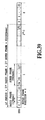
- LC counter information (received, MCC side) The position of a super frame in a long code period when the timing cell is received in the MCC (See, Fig. 39). The value ranges over 0-2 10 -1, and is represented in binary coding.
- LC counter information (transmitted, MCC side) The position of a super frame in a long code period when the timing cell is transmitted from the MCC (See, Fig. 39).
- LC counter information (received, BTS side) All "0s" (this information element is not used in the present system).
- LC counter information (transmitted, BTS side) The position of a super frame in a long code period when the timing cell is received in the BTS (See, Fig. 39). The value ranges over 0-2 10 -1, and is represented in binary coding.
- CRC-10 The value of CRC-10 for ATM cell payload. Generator polynomial: X 10 +X 9 +X 5 +X 4 +X+1. Table 27 Correspondence between SF time information bits and times Bits Times (msec) Oh 0 1h 0.125 2h 0.250 13FFh 639.875
- Allocate fingers so that sufficient receiving characteristics can be obtained for respective diversity branches (space and inter-sector diversities).
- the algorithm for assigning the fingers to the branches is not specified.
- the diversity combining method is a maximal ratio combining.
- a searcher selects paths for RAKE combining from among received branches to achieve optimum receiving characteristics.
- the coherent detection is carried out using pilot blocks (consisting of four pilot symbols each) which are received at every 0.625 ms interval.
- the BTS broadcasts over the BCCH the transmission power of the perch channels and the reverse interfering power.
- a mobile station decides the transmission power of the RACH in accordance with the information.
- the RACH includes information about the received SIR of the perch channel, which is measured by the mobile station.
- the BTS decides in accordance with the information the transmission power of the FACH associated with the RACH received, and designates the transmission power level together with the transmission information.
- the transmission power level is variable at each transmission of the information.
- Its initial transmission power is decided in the same manner as the transmission power of the RACH and FACH.
- the BTS and mobile station proceed to a high speed closed loop control based on the SIR.
- a receiving side periodically compares the measured value of the received SIR with a reference SIR, and transmits to the transmitting side the compared result using the TPC bit.
- the receiving side carries out relative control of the transmission power in accordance with the TPC bit.
- an outer loop function is provided which updates the reference SIR in response to the receive quality.
- range control is carried out which sets the upper and lower limits of the transmission power level.
- the transmission power control of the UPCH is carried out in the same manner as (3) above. That of the RACH during the packet transmission is performed as (1) above. With regard to the FACH during the packet transmission, the transmission is always carried out at a transmission level specified by the transmission power range designation. Unlike the (2) above, the transmission power level is not varied every time the information is transmitted. 5.2.1.2. SIR based high speed closed loop transmission power control.
- the BTS (or mobile station) measures the received SIR every transmission power control interval (0.625 ms), sets the TPC bit at "0" when the measured value is greater than the reference SIR and at "1" when it is lower than that, and transmits the TPC bit to the mobile station (or BTS) in two consecutive bits.
- the mobile station (or BTS) makes a soft decision of the TPC bit, decreases the transmission power by 1 dB when the decision result is "0", and increases it by 1 dB when the decision result is "1".
- the changing timing of the transmission power is immediately before the pilot block.
- the maximum transmission power is designated in the reverse link, and the maximum transmission power and minimum transmission power are designated in the forward link, so that the control is carried out in these ranges (see, Figs. 41A and 41B).
- the transmission power level is fixed.
- Frame timings of the forward and reverse channels are determined such that the positions of the pilot symbols of the two channels are shifted by 1/2 time slot, thereby implementing the transmission power control with one slot control delay (see, Fig. 42).
- Fig. 43 shows a method of shifting from the initial state to the closed loop control.
- the BTS carries out transmission in a fixed transmission power control pattern until it can receive the TPC bit based on the forward SIR measured result. This is the initial operation.
- the initial operation carries out transmission according to a control pattern that will increase the transmission power step by step.
- the initial operation is divided into two stages.
- the BTS can change the fixed TPC pattern mentioned above depending on the interfering amount over the entire cell.
- the mobile station carries out the foregoing reverse transmission power control in accordance with the fixed TPC bit pattern from the base station, it can perform similar transmission power control using a fixed control pattern that is preset in the mobile station. In this case, the pattern is invariable.
- an initial value sent from the base station can be used instead.
- the base station can determine it, a more optimal initial value can be set.
- the BTS and MCC have an outer loop function of updating the reference SIR of the high speed closed loop transmission power control in accordance with quality information to meet the required receive quality (average FER or average BER).
- the MCC performs during the DHO the outer loop control in response to the quality after the selection combining.
- the initial value of the reference SIR is designated.
- the subsequent reference SIR is updated on the basis of measured results of the receive quality. Both the MCC and BTS can determine the update of the reference SIR. The following is an example of a concrete method.
- the measurement of the received SIR and the demodulation of the TPC bits are carried out with both the forward and reverse links after the inter-sector maximal ratio combining.
- the forward TPC bits the same value is transmitted from a plurality of sectors.
- the transmission power control is carried out in the same manner as in the case where no diversity handover is performed.
- Each BTS measures the reverse received SIR as in the case where no diversity handover is performed, and transmits to the mobile station the TPC bits determined in accordance with the measured result.
- the mobile station receives the TPC bits from each BTS independently (with carrying out the inter-sector diversity). At the same time, the mobile station measures the reliability (received SIR) of the TPC bits of each BTS. If any one of the results of the soft majority decision about the TPC bits that meet a predetermined reliability includes "0", the transmission power is reduced by 1 dB. If all the results are "1", the transmission power is increased by 1 dB.
- Each BTS controls the transmission power in accordance with the received TPC bits as in the case where no diversity handover is performed. If the TPC bit cannot be received because of the out-of-sync of the reverse link, the transmission power level is fixed.
- the mobile station measures the received SIR after the site diversity combining, and transmits to each BTS the TPC bits which are determined in accordance with the measured results.
- the mobile station transmits a RACH when carrying out a location registration, or an originating or terminating call.
- the BTS establishes the synchronization of the RACH transmitted at a plurality of frame offsets, and receives it.
- the RACH synchronization can be established so that the reception processing of all the RACH-Ls and RACH-S'es that are transmitted at the four offset timings per 10 msec. can be completed within 0.625 msec.
- the reception processing includes deinterleaving, Viterbi decoding and CRC decoding, besides the capability of making a decision as to whether the transmission of Ack is required or not.
- the BTS measures the propagation delay time due to traveling between the mobile station and the BTS, using the delay time of the RACH received timing with respect to a predetermined timing.
- Figs. 46A and 46B illustrate a detailed flow of the synchronization establishing processing.
- the radio frame number and long code are continuously counted up as usual even at the beginning of the diversity handover, and are not changed abruptly.
- the continuity of user information conveyed is fully guaranteed, and hence no instantaneous interruption takes place.
- Each sector in the same cell transmits the perch channel which is spread using the same long code and the same short code, with keeping the phase difference specified by the system.
- the mobile station receives broadcast information from waiting sectors after completing the initial synchronization.
- the broadcast information includes the sector number of its own and the number of sectors in the same cell.
- the mobile station identifies the long code phases of the other sectors in the same cell, and establishes the perch channel synchronization.
- the BTS knows the reverse long code phase of the channel to be received.
- the BTS carries out path search, and RAKE reception of the paths with high correlation detection values. If the transmission characteristics described at 5.1.2. are satisfied, the RAKE reception is readily possible.
- the decision condition of the frame alignment establishment of the BTS for the dedicated physical channel is that the radio frames whose sync words each include Nb or less unmatched bits continue for SR frames or more.
- the frame number is tacitly decided to establish the super frame alignment.
- the frame number is set such that the frame number becomes zero at the timing lagged behind the timing at which the reverse long code phase is zero by an amount of the frame offset + slot offset as shown in Figs. 87A and 87B. This relationship between the long code phase and the frame number is maintained until the radio channel is released, even if the diversity handover is repeated after the incoming or outgoing call connection.
- the frame number is determined such that the radio frame whose timing is shifted by a predetermined time period from the perch channel frame timing is provided with a frame number equal to the SFN of the perch channel, modulo 64.
- the predetermined time period equals frame offset + slot offset during the incoming or outgoing call connection as illustrated in Figs. 87A and 87B.
- it equals the measured value of the frame time difference - 1/2 slot - ⁇ , where ⁇ is an omitted value for expressing the measured value of the frame time difference - 1/2 slot in terms of a symbol unit.
- the present system does not possess any special resynchronization establishing processing procedure because the optimum path search by the searcher is equivalent to carrying out continuous resynchronization.
- a out-of-phase decision method of the BTS in the radio section for the dedicated physical channel will now be described. The following two conditions are monitored.
- Condition 1 Whether or not the number of unmatched bits in a sync word is equal to or less than Nb.
- Condition 2 Whether or not the CRC on the DTCH selection combining unit basis or on the UPCH internal encoding unit basis is correct.
- Radio frames that satisfy at least one of the two conditions continue for SR frames or more in the out-of-sync state, a decision is made that the synchronous state takes place, where SR is the number of reverse synchronization guarding stages.
- the maximal ratio combining is carried out for the entire symbols of the physical channel in the same manner as the space diversity of the received signals from a plurality of sector antennas.
- the reverse transmission power control is carried out using the receive quality after the maximal ratio combining. That is, the forward TPC symbols are set using the receive quality after the maximal ratio combining.
- the same symbol is transmitted from the plurality of the sector antennas.
- the transmission timing control is carried out in the same manner as the inter-cell diversity handover (see 4.1.3. for more details). *As for the wire transmission, the link establishment and transmission are carried out in the same manner as when the diversity handover is not being performed.
- the packet transmission control is applied to the following services.
- the purpose is to transmit data of various traffic characteristics from low density light traffic to high density heavy traffic with efficiently utilizing radio resources and facility resources.
- Major features will be described below.
- the physical channels are switched as needed in accordance with the transmission functions like time varying traffic volume.
- UPCH dedicated physical channels
- the switching control between the physical channels are carried out frequently. If the switching control involves the wire transmission control, this will lead not only to an increase of a wire transmission control load, the wire transmission cost and the control load of the BSC and MSC, but also to an increase in the switching control delay, resulting in the degradation in the quality of service. To avoid this, the switching control must be carried out only between the MS and BTS, thereby obviating the wire transmission control and BSC and MSC control involved in the switching control.
- the diversity handover is impossible because the transmitting and receiving timings cannot be set freely as in the dedicated physical channel.
- HHO hard handover
- the HHO Since the HHO is carried out at a high frequency, if the HHO processing involves the wire transmission control, this will lead not only to an increase of a wire transmission control load, that of the wire transmission cost and that of the control load of the BSC and MSC, but also to an increase in the HHO control delay, resulting in the degradation in the quality of service.
- the wire section uses the diversity handover, and only the radio section employs the HHO.
- the HHO control is carried out only between the MS and BTS, thereby obviating the wire transmission control and BSC and MSC control involved in the HHO control.
- Figs.. 48-51 shows examples of the connection configuration during the inter-sector handover.
- the inter-sector DHO since the inter-sector DHO is controllable independently of the BTS, the inter-sector DHO that uses the maximal ratio combining is carried out for both the forward and reverse links in the packet transmission as in the circuit switching mode.
- UPCH dedicated physical channel
- the switching control is carried out in the BTS and mobile station such that the transmission and reception are carried out with only one sector in accordance with the propagation loss of the perch channel.
- the switching control method is the same as the inter-cell handover processing as shown in Fig. 47.
- the BTS that covers the location sector of the mobile station makes a decision of the switching on the basis of the following factors.
- the following factors are available, and the factors to be used are selectable.
- the factors 1 and 2 become available when the report of the information about the factors is started.
- Factor 1 In-band information (information about the physical channel which is desired to be used) fed from the ADP of the MCC and the ADP of the MS.
- Factor 2 Monitoring of the forward/reverse traffic volume by the BTS.
- Factor 3 A layer 3 signal that requires from the MS to the BTS switching of the channel to be used.
- a decision of switching is made by comparing the information reported by the factors of the foregoing section (2) with predetermined thresholds.
- the BTS makes the switching decision if any one of the foregoing switching decision factors takes place.
- the BTS instructs through the FACH the MS to establish a dedicated physical channel, and establishes the designated dedicated physical channel between the MS.
- the BTS changes the connection of the wire link and radio link with the MS from the common control physical channel to the dedicated physical channel.
- the BTS communicates over the dedicated physical channel which has been established.
- the BTS makes a decision of the switching to a common control physical channel.
- the BTS instructs through the UPCH the MS to release the dedicated physical channel which is being used.
- the MS Receiving the instruction to release the dedicated physical channel, the MS makes a response to that, and releases the dedicated physical channel which is being used. Then, the MS starts the FACH reception of the common physical channel.
- the BTS releases the dedicated physical channel which is used between it and the MS, and changes the connection of the wire link and radio link with the MS. Subsequently, the BTS communicates over the common control physical channel which has been established. *The switching control is processed only in the radio section between the mobile station and the BTS, without involving BSC and wire section at all.
- the switching control is based only on the decision the base station makes, and does not involve any switching control of the wire section (between the base station and the control center (BSC), for example), it is possible to reduce the load of the switching control, and to speed up the switching control.
- the control signal between the mobile station and the BTS is a layer 3 signal, and is processed by the BTS. In this case, the BTS must change the connection between the wire link and radio link in accordance with the instructions as described before.
- the ATM cells are transmitted at 6.3 M using TS1-TS96 without using TS97 and TS98, and at 1.5 M using all the TS1-TS24. In this case, although it is unnecessary to recognize the delimiter between the 53 bytes of the ATM cells, the delimiters between time slots and between octets of the ATM cells are transmitted in conjunction with the boundary.
- the ATM cells are extracted from the TS1-TS96 with ignoring the data of the TS97 and TS98, at 6.3 M. At 1.5 M, the ATM cells are extracted from the TS1-TS24.
- the physical interface inserts idle cells for adjusting the cell rate and for matching the two rates.
- the idle cell Since the idle cell has a fixed pattern, its header can be identified by "00000000 00000000 00000001 01010010". Its pattern in the information field consists of iterative sequences of "01101010" (see, Fig. 32).
- the idle cell is used only for cell synchronization on the receiver side, without any other role. *Cell level scrambling (applied only to 6.3 M).
- ATM cells have different VCI/VPI for each application or for each user, and transfer themselves to respective processing sections by identifying the VPI/VCI.
- each application Since different VCIs are multiplexed on each VPI basis to be transmitted in the reverse direction signal, each application outputs its reverse direction ATM cell signal with band assurance control. *Cell header structure.
- the ATM cell comprises a cell header as shown in Fig. 54.
- the cell header includes 8-bit VPI and 16-bit VCI, and the details of their coding are specified separately between the switching system and the base station. *ATM header coding.
- the transmission order of bits of the ATM cell is determined such that the bits in each octet are sent from the bit number 8, and the octets are sent from the octet number 1. Thus, they are transmitted from the MSB.
- VPI/VCI As for the routing bits of the VPI/VCI, there are specified three types of VPIs in the interface between the base station and the switching center, and 256 types (8 bits) of VCIs from 0-255. *Channel number/VPI/VCI setting (initial state).
- the channel number is fixedly corresponds to the mounted position of a HW interface card and the connector position in the card.
- VPI The VPI is always "0" (not used in practice).
- VCI The VCI is specified when a link of a wire transmission path is established.
- the AAL-Type 2 protocol is intended to provide variable rate services that have timing dependence between the transmitting and receiving ends, such as voices which are subjected to variable rate encoding.
- AAL-2 is required to carry out real time data transfer to the higher layer between transmitting and receiving sides at a variable rate, with particular timing conditions. In addition, it is required to achieve information transfer for matching the clock and timing between the transmitting and receiving sides, and to carry out transfer of information about data structure.
- the AAL-2 must have the capability of dealing with, besides the timing conditions like those of AAL-1, multiplexing for multimedia multiplexing of data and voice, and of handling a variable rate, cell loss and cell priority.
- the control signal and traffic signal in a forward direction signal can be separated by first identifying the AAL type. There are AAL-2 and AAL-5 in the AAL type, and they can be identified by the VCI (see, 4.2.2.1.).
- control signal between the BTS and MCC in the AAL-5 connection can be separated from the super frame phase correction cell by the VCI because their VCIs are different.
- the AAL-2 connection further includes CIDs for identifying users, and carries out the separation using the CIDs that are different for each call.
- FIG. 55 illustrates the outline of the band assurance control.
- the band assurance control determines the transmission order of short cells and standard cells in accordance with the following quality classes, and establishes respective bands. More specifically, the band assurance control, being based on the precondition that the short cells and standard cells are discarded if they exceed a maximum tolerable delay time, determines transmission orders of the short cells and standard cells for respective quality classes such that the cell loss ratio becomes equal to a maximum cell loss ratio.
- the setting method of the transmission order is specified.
- the VCI is associated with one of the following AAL-Type 5 quality classes by setting a MATM connection ID.
- the VCI and CID are associated with one of the following AAL-Type 2 quality classes by setting the MATM connection ID.
- Table 28 shows the correspondence between services and the quality classes.
- the quality class is set in conjunction with the connection establishment of the wire transmission path.
- the timing cell VC is always assigned top priority (delay time is 0 ms, and loss rate is 0). (maximum tolerable delay time; allowable cell loss ratio) (top priority of 0 ms delay; loss ratio 0) (5 ms; 10 -4 ) (5 ms; 10 -7 ) (50 ms; 10 -4 ) (50 ms; 10 -7 ) (AAL-Type 2)
- Table 28 shows the correspondence between services and the quality classes.
- the quality class is set in conjunction with the connection establishment of the wire transmission path. (maximum tolerable delay time; allowable cell loss ratio) (5 ms; 10 -4 ) (5 ms; 10 -7 ) (50 ms; 10 -4 ) (50 ms; 10 -7 )
- the band assignment to the AAL-Type 2 quality classes can be made different for each VC.
- the transmission order of the short cells can be changed for each VC.
- Fig. 56 illustrates a transmission procedure of the reverse direction ATM cell
- Fig. 57 illustrates an assembling procedure of reverse direction co-transmitted cells of the AAL-Type 2 level.
- the cell transmission sequence data is specified in correspondence with the quality classes at the start up of the BTS.
- short cells and standard cells to be transmitted are selected from the quality classes, subjected to the multiplexing, and formed into transmission cells. If a cell of the target quality is not present in the buffer, a cell in the next quality can be transmitted.
- FIGs. 58A-58C show examples of the cell transmission sequence data corresponding to Table 28. Transmission cycles of A, B, C, ..., L are determined in accordance with allocated bands of respective ATM bands A, B, C, ..., F (for example, ACADAFAC).
- transmission sequences for compositing the short cells are determined depending upon respective SC bands E1 - F4 such that the respective quality classes are satisfied (for example, F2F1F2F3F4).
- the AAL-5 is a simplified AAL type that is provided for transferring signaling information. It differs from the other. AAL types in that its payload has no header trailer, and hence can transfer 48 bytes with a minimum communication overhead. *Functions of the AAL-5.
- the AAL-5 carries out the error detection not on a cell by cell basis but on a user frame by user frame basis to improve the efficiency of the data transmission.
- the error detection is performed using CRC-32 check bits.
- the CRC is given for each user frame, and is effective in a poor transmission quality environment because of its high detection capability due to 32 bits.
- Fig. 59 shows the format of the AAL-5.
- the receiving side carries out the following operations.
- Fig. 60 illustrates an example of the sequence from the establishment to the release of the SSCOP link.
- the SSCOP is applied to the control signal VC and paging VC between the BTS and MCC, and is processed by the BTS and MCC.
- the reverse direction delay adding function is provided for measuring system immunity by adding delays to reverse signals when carrying out a test of combining reverse signals between different base stations.
- a delay up to a maximum of 100 ms can be added to the reverse signal at every 0.625 ms step (frame offset step).
- the delay amount can be set by a dip switch.
- the BTS carries out with the MCC the time synchronization establishing processing of the SFN (System Frame Number) which will be described below.
- the SFN clock the MCC generates is the master clock of the entire system.
- the SFN synchronization processing is provided for establishing in the BTS the time synchronization with the SFN clock of the MCC.
- the target for the range of the time synchronization error is set within 5 msec.
- the BTS uses as its internal reference clock the SFN clock after the synchronization is established.
- the timings of the transmitting and receiving radio channels in respective sectors under the control of the BTS are generated from the reference SFN clock of the BTS (see, Figs. 85-88B).
- the SFN synchronization establishment is implemented by exchanging the timing cells between the MCC and BTS.
- Fig. 61 illustrates the detail of the procedure which will be described below.
- the numerals in Fig. 61 correspond to the numbers in the following descriptions.
- the BTS at turn-on or at start up after a reset, generates a temporary SFN clock signal.
- the BTS acquires a transmitting time (a time within a super frame, and the super frame position in a long code period) of a timing cell 1 to be transmitted from the BTS to the MCC.
- the transmitting time is based on the temporary SFN clock signal.
- the BTS generates the timing cell 1. Values of information elements in the timing cell 1 are set as shown in Table 29.
- Table 29 Information elements Specified values Message ID 03h; Timing Report (BTS ⁇ MCC) SF time information (received, MCC-SIM side) all 0 SF time information (transmitted, MCC-SIM side) all 0 SF time information (transmitted, BTS side) The time within the super frame in the time information acquired in (2).
- LC counter information (received, MCC-SIM side) all 0 LC counter information (transmitted, MCC-SIM side) all 0 LC counter information (transmitted, BTS side) The super frame position in the long code period in the time information acquired in (2).
- Other information elements In accordance with Table 26.
- the BTS transmits the timing cell 1 it generated in (3) at the transmission timing it acquired in (2).
- the MCC receives the timing cell 1, and acquires the received time (the time within the super frame and the super frame position in the long code period). This time is based on the SFN clock generated by the MCC.
- the MCC acquires a transmitting time (a time within a super frame, and the super frame position in a long code period) of a timing cell 2 to be transmitted from the MCC to the BTS. This time is a transmitting time based on the temporary SFN clock generated by the MCC.
- the MCC generates the timing cell 2. Values of information elements in the timing cell 2 are set in accordance with Table 30.
- Table 30 Information elements Specified values Message ID 02h; Timing Report (MCC ⁇ BTS) SF time information (received, MCC side) The time within the super frame in the time information acquired in (5).
- SF time information (transmitted, MCC side) The time within the super frame in the time information acquired in (6).
- SF time information (transmitted, BTS side) The time within the super frame in the time information acquired in (2) (The MCC sets this information element in the timing cell received in (5) to the same value again).
- LC counter information (received, MCC side) The super frame position in the long code period in the time information acquired in (5) .
- LC counter information (transmitted, MCC side) The super frame position in the long code period in the time information acquired in (6).
- LC counter information (transmitted, BTS side)
- the super frame position in the long code period in the time information acquired in (2) (The MCC sets this information element in the timing cell received in (5) to the same value again). Other information elements In accordance with Table 26.
- the MCC transmits the timing cell 2 it generated in (7) at the transmission timing it acquired in (6).
- the BTS receives the timing cell 2, and acquires the received time (the time within the super frame and the super frame position in the long code period). This time is a received time based on the temporary SFN clock in the BTS.
- the BTS calculates the corrected value X of the temporary SFN clock phase from the information elements of the timing cell 2 it receives.
- Fig. 62 illustrates the calculation method and calculation basis of the corrected value. Calculation results of the corrected value are stored in a memory. In Fig. 62,
- the BTS stops the transmission of the timing cell, and lights up an ERR lamp on the card including the transmission path interface.
- the BTS brings the SFN timing into a free-running state, and performs the transmission control of the radio section in accordance with the free-running SFN.
- the BTS generates the reference clock from the HWY, and generates various clock signals from the reference clock.
- the BTS When the BTS is connected with a plurality of 1.5 M HWYs, it can select with a hard switch like a dip switch the HWY used for generating the clock.
- the BTS generates, after establishing the SFN time synchronization at the start up, the reference SFN clock only from the clock that is generated from the HWY. If a restart processing is not carried out, the reference SFN clock of the BTS will not be changed by any other factors.
- the BTS does not perform autonomous SFN synchronization correction. Besides, it does not carry out a synchronization correction processing triggered by a synchronization correction request from the MCC.
- a transfer processing method by the BTS of the information transmitted between the MCC and MS varies depending on the type of the logical channels in the radio section. The processing method will be described below. The following description has nothing to do with the transmission information between the MCC and BTS.
- radio section links Physical channels and logical channels
- wire section links channel number, VPI, VCI and CID
- Table 31 shows, for each logical channel, a processing method of the transmission information which is received from the wire section.
- Table 31 Processing method of transmission information received from wire section.
- Logical channel Description DTCH *Assembles a radio unit from the transmission information in a received short cell, and transmits it in a radio frame with the same frame number as the FN in the SAL of the short cell. *Discards the user information in the received short cell if the transmission to the wire section is not completed before the expiration of a timer ADTCH which is started when the short cell is received.
- the value of the timer ADTCH is specified as one of the system parameters in the range from 0.625 msec to 640 msec at every 0.625 msec step.
- the value of the timer AACCH is specified as one of the system parameters in the range from 0.625 msec to 640 msec at every 0.625 msec step.
- SDCCH *Assembles the CPD PDU for the transmission information in a received short cell, carries out dividing processing at every internal encoding unit, performs processings up to assembling of a radio unit, and transmits it in a radio frame that can be transmitted first.
- the controller of the MCC transmits the control information on a CPS-SDU unit basis with spacing such that the rate of the SDCCH in the radio section is not exceeded.
- FACH for packet transmission
- FACH (for packet transmission) *Assembles the CPD PDU for the information in a received short cell or in a standard cell, carries out dividing processing at every internal encoding unit, performs processings up to assembling of a radio unit, and transmits it in a radio frame that can be transmitted first. If divided into a plurality of internal encoding units, a plurality of radio units are transmitted successively.
- UPCH The EX-interface for packets of the MCC transmits the control information on a CPS-SDU unit basis with spacing such that the rate of the UPCH in the radio section, which rate is required at the call setup as a peak rate, is not exceeded.
- a receiving buffer of the information from the UPCH wire transmission path it is enough for a receiving buffer of the information from the UPCH wire transmission path to have an area that can accommodate only a few frames corresponding to the CPS-SDU with a maximum length.
- a FACH buffer In a state in which the FACH is established, because the rate of the radio section can be lower than the peak rate, a FACH buffer must have a rather large size. *Makes OFF the transmission of the UPCH symbols as for a radio frame that does not receive any transmission information from the wire section.
- Table 32 shows, for each logical channel, a processing method of the transmission information which is received from the radio section.
- Table 32 Processing method of transmission information received from radio section.
- Mode 2 Transmission information is always sent to the wire section after the Viterbi decoding.
- DTCH 64 ksps or more dedicated physical channel
- ACCH ACCH *Assembles a radio frame from ACCH bits in one or more radio frames, and carries out the Viterbi decoding and CRC checking.
- SDCCH *Carries out the Viterbi decoding and CRC checking for the transmission information in a radio frame. Generates the CPS PDU in accordance with the W bits only when the CRC checking is correct. Assembles a short cell when the generation of the CPS PDU is completed and the CRC checking of the CPS is correct, and sends it to the wire section at the earliest timing available.
- RACH for packet transmission
- CPS PDU the CPS PDU in accordance with the W bits and S bits only when the CRC checking is correct. Assembles a short cell when the generation of the CPS PDU is completed and the CRC checking of the CPS is correct, and sends it to the wire section at the earliest timing available.
- SAT is always set at "00" for all logical channels.
- the FN of a received radio frame is used as the FN of the SAL of the short cell or standard cell including the transmission information which is transmitted by the radio frame.
- the FN of the received radio frame is determined on the basis of the reverse long code phase by the following expression.
- the FN of the first one of the plurality of radio frames is used as the FN in the SAL.
- a method for deciding the FN of the radio frame is the same as that of the foregoing (1).
- the FN of the first radio frame of one or more radio frames constituting the CPS-PDU is adopted as the FN in the SAL.
- a method for deciding the FN of the radio frame is the same as that of the foregoing (1).
- the sync is set to "0" if the received radio frame is in the synchronization state, and to "1” if it is in the out-of-sync state.
- the value of the BER is set on the basis of a result of the BER estimated value degradation decision which is carried out for each radio frame.
- the value of the BER is set on the basis of a result of the BER estimated value degradation decision which is carried out for each radio frame.
- the value of the BER is set on the basis of a result of the BER estimated value degradation decision which is carried out for each CPS-PDU.
- the value of the Level is set on the basis of a result of the level degradation decision which is made for each radio frame.
- the value of the Level is set on the basis of a result of the level degradation decision which is made for each radio frame.
- the value of the Level is set on the basis of a result of the level degradation decision which is made for each CPS-PDU.
- the value of the CRC is set on the basis of a result of the CRC checking which is carried out for each selection combining unit.
- the value of the CRC is set on the basis of a result of the CRC checking which is carried out for each radio unit.
- the value of the CRC is set on the basis of a result of the CRC checking which is carried out for each CPS-PDU. However, since the transmission to the wire link is carried out only when the CRC is correct, it is substantially "0", normally.
- the value of the SIR is set on the basis of a result of the SIR measurement which is carried out for each radio unit.
- the value of the SIR is set on the basis of a result of the SIR measurement which is carried out for each radio unit.
- the value of the SIR is set on the basis of a result of the SIR measurement which is carried out for each CPS-PDU (if the CPS-PDU ranges over a plurality of radio frames, the average value over the plurality of radio frames is used as the result) .
- the values of the RCN and RSCN are set in accordance with Table 24.
- Table 33 shows a processing for each logical channel, when the out-of-sync method as described in 5.5.2.3. makes an out-of-sync decision, in which RACH is not handled because the out-of-sync decision is not applied to the common control physical channel.
- Table 33 Logical Description DTCH SDCCH *Generates a cell whose Sync bit in the SAL is set at "1", and sends the short cell to the wire section every 10 msec interval until the synchronization is recovered.
- UPCH *A short cell of the UPCH does not include user information.
- SAT 00 FN: As an estimated value, one of the values 0-63 is set which is incremented at every 10 msec interval. It is set such that it keeps continuity from before the out-of-sync decision.
- BER 1 Level: 1
- CRC 1 SIR: all 0s RCN, RSCN: according to Table 27 (as in the synchronization holding state).
- Fig. 63 illustrates a flow of the cell loss detection.
- *Frame number (FN) It is used for the cell loss detection in all the unrestricted services.
- RSCN Radio subchannel number
- RCN Radio channel number
- the cell loss is detected using the foregoing four parameters.
- Table 34 shows the processing method of the cell loss detection.
- Table 34 Processing method of cell loss detection.
- the novel base station equipment of the mobile communication system in accordance with the present invention is best suited for high speed CDMA digital communications.
Landscapes
- Engineering & Computer Science (AREA)
- Computer Networks & Wireless Communication (AREA)
- Signal Processing (AREA)
- Quality & Reliability (AREA)
- Mobile Radio Communication Systems (AREA)
Applications Claiming Priority (3)
| Application Number | Priority Date | Filing Date | Title |
|---|---|---|---|
| JP11619297 | 1997-04-17 | ||
| JP11619297 | 1997-04-17 | ||
| EP19980914086 EP1011211B1 (de) | 1997-04-17 | 1998-04-17 | Empfänger und Verfahren für den kohärenten Empfang mittels empfangener Pilotsymbole |
Related Parent Applications (1)
| Application Number | Title | Priority Date | Filing Date |
|---|---|---|---|
| EP98914086.8 Division | 1998-10-22 |
Publications (1)
| Publication Number | Publication Date |
|---|---|
| EP1492376A1 true EP1492376A1 (de) | 2004-12-29 |
Family
ID=14681121
Family Applications (9)
| Application Number | Title | Priority Date | Filing Date |
|---|---|---|---|
| EP20040077701 Withdrawn EP1492376A1 (de) | 1997-04-17 | 1998-04-17 | Basisstation für mobile Telekommunikationsanordnung |
| EP19980914086 Expired - Lifetime EP1011211B1 (de) | 1997-04-17 | 1998-04-17 | Empfänger und Verfahren für den kohärenten Empfang mittels empfangener Pilotsymbole |
| EP20040077684 Expired - Lifetime EP1492368B1 (de) | 1997-04-17 | 1998-04-17 | Basisstation und Verfahren für Mobilkommunikationssystem |
| EP20100165215 Withdrawn EP2224623A3 (de) | 1997-04-17 | 1998-04-17 | Basisstation für mobile Telekommunikationsanordnung |
| EP20040077683 Withdrawn EP1492254A1 (de) | 1997-04-17 | 1998-04-17 | Erzeugung von Kodes für ein Mobilkommunikationssystem |
| EP20040077685 Withdrawn EP1501218A1 (de) | 1997-04-17 | 1998-04-17 | Basisstation für mobile Telekommunikationsanordnung |
| EP20040077666 Expired - Lifetime EP1499039B1 (de) | 1997-04-17 | 1998-04-17 | Sendegerät für ein Mobilfunksystem |
| EP20040077682 Expired - Lifetime EP1494372B1 (de) | 1997-04-17 | 1998-04-17 | Anordnung und Verfahren zur Telekommunikation |
| EP20040077686 Expired - Lifetime EP1499036B1 (de) | 1997-04-17 | 1998-04-17 | Mobiles Kommunikationssystem, Basisstation und Mobilstation |
Family Applications After (8)
| Application Number | Title | Priority Date | Filing Date |
|---|---|---|---|
| EP19980914086 Expired - Lifetime EP1011211B1 (de) | 1997-04-17 | 1998-04-17 | Empfänger und Verfahren für den kohärenten Empfang mittels empfangener Pilotsymbole |
| EP20040077684 Expired - Lifetime EP1492368B1 (de) | 1997-04-17 | 1998-04-17 | Basisstation und Verfahren für Mobilkommunikationssystem |
| EP20100165215 Withdrawn EP2224623A3 (de) | 1997-04-17 | 1998-04-17 | Basisstation für mobile Telekommunikationsanordnung |
| EP20040077683 Withdrawn EP1492254A1 (de) | 1997-04-17 | 1998-04-17 | Erzeugung von Kodes für ein Mobilkommunikationssystem |
| EP20040077685 Withdrawn EP1501218A1 (de) | 1997-04-17 | 1998-04-17 | Basisstation für mobile Telekommunikationsanordnung |
| EP20040077666 Expired - Lifetime EP1499039B1 (de) | 1997-04-17 | 1998-04-17 | Sendegerät für ein Mobilfunksystem |
| EP20040077682 Expired - Lifetime EP1494372B1 (de) | 1997-04-17 | 1998-04-17 | Anordnung und Verfahren zur Telekommunikation |
| EP20040077686 Expired - Lifetime EP1499036B1 (de) | 1997-04-17 | 1998-04-17 | Mobiles Kommunikationssystem, Basisstation und Mobilstation |
Country Status (8)
| Country | Link |
|---|---|
| US (11) | US6782035B1 (de) |
| EP (9) | EP1492376A1 (de) |
| JP (2) | JP3884774B2 (de) |
| KR (1) | KR100349102B1 (de) |
| CN (8) | CN1510945A (de) |
| CA (2) | CA2424556C (de) |
| DE (5) | DE69839852D1 (de) |
| WO (1) | WO1998047246A1 (de) |
Families Citing this family (153)
| Publication number | Priority date | Publication date | Assignee | Title |
|---|---|---|---|---|
| EP1492376A1 (de) * | 1997-04-17 | 2004-12-29 | NTT DoCoMo, Inc. | Basisstation für mobile Telekommunikationsanordnung |
| JP3655057B2 (ja) * | 1997-07-19 | 2005-06-02 | 松下電器産業株式会社 | Cdma送信装置及びcdma送信方法 |
| WO2000028763A1 (en) * | 1998-11-09 | 2000-05-18 | Samsung Electronics Co., Ltd. | Reservation multiple access in a cdma communications system |
| US6512925B1 (en) * | 1998-12-03 | 2003-01-28 | Qualcomm, Incorporated | Method and apparatus for controlling transmission power while in soft handoff |
| WO2000038450A1 (fr) * | 1998-12-21 | 2000-06-29 | Hitachi, Ltd. | Procede de communication mobile utilisant une technique de multiplexage amrc et systeme de communication mobile |
| KR100684920B1 (ko) | 1999-02-13 | 2007-02-22 | 삼성전자주식회사 | 부호분할다중접속 통신시스템의 페이징 채널 할당장치 및 방법 |
| US6574267B1 (en) * | 1999-03-22 | 2003-06-03 | Golden Bridge Technology, Inc. | Rach ramp-up acknowledgement |
| US6456606B1 (en) | 1999-03-24 | 2002-09-24 | Qualcomm Incorporated | Handoff control in an asynchronous CDMA system |
| US7929592B1 (en) | 1999-04-02 | 2011-04-19 | Ntt Docomo, Inc. | Channel estimation device and method, demodulation device and method, and fading frequency decision device and method |
| JP4955850B2 (ja) * | 1999-04-08 | 2012-06-20 | テキサス インスツルメンツ インコーポレイテッド | Wcdmaのためのダイバーシティ検出 |
| GB9908518D0 (en) | 1999-04-14 | 1999-06-09 | Nokia Telecommunications Oy | Method for controlling transmission power |
| GB9912846D0 (en) * | 1999-06-02 | 1999-08-04 | Nokia Telecommunications Oy | A method of controlling power |
| JP3202730B2 (ja) * | 1999-06-08 | 2001-08-27 | 日本電気移動通信株式会社 | 移動無線システム |
| EP1104977A4 (de) | 1999-06-15 | 2005-12-21 | Ntt Docomo Inc | Verfahren zur aktualisierung von nebenbasisstation, informationskontrollverfahren zur zellensuche in mobilkommunikationssystem, zellensuchverfahren in mobilstation, mobilkommunikationssystem, basisstation und kontrollstation |
| CN1395768A (zh) | 2000-01-14 | 2003-02-05 | 交互数字技术公司 | 数据传输块尺寸可选择的无线通信系统 |
| US6996069B2 (en) | 2000-02-22 | 2006-02-07 | Qualcomm, Incorporated | Method and apparatus for controlling transmit power of multiple channels in a CDMA communication system |
| US20030060224A1 (en) | 2000-02-23 | 2003-03-27 | Tantivy Communications, Inc. | Reverse link initial power setting using effective radiated power message to compute path loss |
| CN1187935C (zh) * | 2000-04-06 | 2005-02-02 | 株式会社Ntt都科摩 | 多点传播传送方法及多点传播传送系统与移动台及基地台 |
| GB0008488D0 (en) * | 2000-04-07 | 2000-05-24 | Koninkl Philips Electronics Nv | Radio communication system and method of operating the system |
| FI20000853A7 (fi) * | 2000-04-10 | 2001-10-11 | Nokia Corp | Tiedonsiirtomenetelmä |
| WO2001084876A1 (en) * | 2000-04-19 | 2001-11-08 | Nokia Corporation | Method and system for connection set-up in a communication system comprising several switching units and several processing units |
| JP3390406B2 (ja) * | 2000-05-11 | 2003-03-24 | 中部日本電気ソフトウェア株式会社 | ファイル転送方法、及びそのシステム |
| US7058020B2 (en) * | 2000-05-18 | 2006-06-06 | Brix Networks, Inc. | Hardware time stamping and registration of packetized data method and system |
| JP3583353B2 (ja) * | 2000-07-03 | 2004-11-04 | 松下電器産業株式会社 | 通信端末装置および基地局装置 |
| GB0018482D0 (en) * | 2000-07-26 | 2000-09-13 | Koninkl Philips Electronics Nv | Radio communication system |
| WO2002009309A2 (en) * | 2000-07-26 | 2002-01-31 | Koninklijke Philips Electronics N.V. | Power control in a radio communication system |
| US7023933B2 (en) * | 2000-10-20 | 2006-04-04 | Matsushita Electric Industrial Co., Ltd. | Radio communication apparatus |
| SE0004326D0 (sv) * | 2000-11-24 | 2000-11-24 | Ericsson Telefon Ab L M | Base station identification |
| CN1254149C (zh) * | 2000-12-22 | 2006-04-26 | 西门子公司 | 异步转移模式传输方法和装置 |
| JP3857528B2 (ja) * | 2001-01-12 | 2006-12-13 | 富士通株式会社 | 同期検出装置 |
| US6912211B2 (en) * | 2001-01-26 | 2005-06-28 | At&T Corp. | CDMA to packet-switching interface for code division switching in a terrestrial wireless system |
| WO2002082847A1 (en) | 2001-04-05 | 2002-10-17 | Nokia Corporation | Allocation period determination for packet data |
| US6804220B2 (en) * | 2001-05-07 | 2004-10-12 | Qualcomm Incorporated | Method and apparatus for generating control information for packet data |
| US7336693B2 (en) * | 2001-05-08 | 2008-02-26 | Sony Corporation | Communication system using ultra wideband signals |
| FR2827098B1 (fr) * | 2001-07-05 | 2003-12-05 | Nortel Networks Ltd | Procede de controle de ressources radio affectees a une communication entre un terminal mobile et une infrastructure cellulaire a etalement de spectre, et equipements pour la mise en oeuvre du procede |
| JP2003061142A (ja) * | 2001-08-09 | 2003-02-28 | Matsushita Electric Ind Co Ltd | Cdma移動通信方法およびシステム |
| KR20030016811A (ko) * | 2001-08-22 | 2003-03-03 | 주식회사 젤라인 | 전력선 통신시스템의 패킷 통신방법 |
| JP4005796B2 (ja) * | 2001-11-30 | 2007-11-14 | 富士通株式会社 | 電力制御回路および無線送信装置 |
| CN100425013C (zh) * | 2002-01-08 | 2008-10-08 | Ipr特许公司 | 在无线通信系统的反向链路中维持保持信道 |
| JP2005516469A (ja) * | 2002-01-22 | 2005-06-02 | アイピーアール・ライセンシング・インコーポレーテッド | 通信システムにおけるオーバーヘッドの低減 |
| EP1335289A1 (de) * | 2002-02-07 | 2003-08-13 | Siemens Aktiengesellschaft | Verfahren zum Software Download in einem Radiokommunikationssystem |
| US7292552B2 (en) * | 2002-03-14 | 2007-11-06 | Qualcomm Incorporated | Method and apparatus for reducing interference in a wireless communication system |
| KR100630128B1 (ko) * | 2002-03-23 | 2006-09-27 | 삼성전자주식회사 | 고속 순방향 패킷 접속 방식을 사용하는 이동통신시스템에서 역방향 전력 제어를 위한 파일럿 신호필드 위치정보 결정장치 및 방법 |
| JP3843037B2 (ja) * | 2002-04-17 | 2006-11-08 | 松下電器産業株式会社 | 通信装置及び通信装置の送信電力制御方法 |
| WO2003103328A1 (ja) * | 2002-05-31 | 2003-12-11 | 三菱電機株式会社 | 通信システム |
| US20050099968A1 (en) * | 2002-06-25 | 2005-05-12 | Osamu Yamano | Power control method and apparatus |
| KR100487234B1 (ko) * | 2002-07-02 | 2005-05-03 | 삼성전자주식회사 | 이동통신 기지국 시스템 |
| JP2004112597A (ja) * | 2002-09-20 | 2004-04-08 | Matsushita Electric Ind Co Ltd | 基地局装置及びパケット品質推定方法 |
| TW200514452A (en) * | 2002-10-03 | 2005-04-16 | Interdigital Tech Corp | Determination of code transmit power range in downlink power control for cellular systems |
| US8780898B2 (en) * | 2002-10-31 | 2014-07-15 | Agere Systems Llc | Processor for packet switching between cell streams with optional virtual channel and channel identification modification |
| US8019362B2 (en) * | 2003-02-07 | 2011-09-13 | Sybase 365, Inc. | Universal short code administration facility |
| DE10306171B4 (de) | 2003-02-13 | 2007-02-08 | Siemens Ag | Verfahren zum Einstellen der Sendeleistungen zweier Kanäle einer Verbindung, Station und Kommunikationssystem |
| US7299402B2 (en) * | 2003-02-14 | 2007-11-20 | Telefonaktiebolaget Lm Ericsson (Publ) | Power control for reverse packet data channel in CDMA systems |
| US8254358B2 (en) | 2003-03-06 | 2012-08-28 | Ericsson Ab | Communicating a broadcast message to change data rates of mobile stations |
| JP3922571B2 (ja) * | 2003-03-26 | 2007-05-30 | ソニー株式会社 | 情報処理装置および情報処理方法、記録媒体、並びに、プログラム |
| KR100981507B1 (ko) * | 2003-04-14 | 2010-09-10 | 삼성전자주식회사 | 블록 확산 코드분할 다중접속 이동통신 시스템에서 트래픽 발생 및 수신 장치 및 방법 |
| DE10324470A1 (de) * | 2003-05-30 | 2005-03-10 | Deutsche Telekom Ag | Verfahren und Vorrichtung zum Steuern von Datenverbindungen in einem Datennetz mit einer Vielzahl von Datennetzknoten |
| KR20050029254A (ko) * | 2003-09-20 | 2005-03-24 | 삼성전자주식회사 | 광대역 무선 통신시스템의 슬리핑 스테이트에서 모드간의상태 천이를 위한 웨이크업 채널 전송 장치 및 방법 |
| KR100582575B1 (ko) * | 2003-10-27 | 2006-05-23 | 삼성전자주식회사 | 멀티 프레임을 이용한 무선 통신 시스템의 데이터 전송방법 |
| US7437135B2 (en) | 2003-10-30 | 2008-10-14 | Interdigital Technology Corporation | Joint channel equalizer interference canceller advanced receiver |
| SE0303031D0 (sv) * | 2003-11-12 | 2003-11-12 | Ericsson Telefon Ab L M | Inter-Frequency and inter-rat handover measurements |
| US7400692B2 (en) | 2004-01-14 | 2008-07-15 | Interdigital Technology Corporation | Telescoping window based equalization |
| US8060143B2 (en) * | 2004-01-16 | 2011-11-15 | Airwalk Communications, Inc. | Combined base transceiver station and base station controller |
| JP2005303499A (ja) * | 2004-04-08 | 2005-10-27 | Nippon Telegr & Teleph Corp <Ntt> | 拡散符号生成回路および同期回路 |
| US7551597B2 (en) | 2004-05-06 | 2009-06-23 | Telefonaktiebolaget L M Ericsson (Publ) | Methods and apparatus for fast downlink information of uplink out-of-synchronization |
| US7437175B2 (en) * | 2004-05-06 | 2008-10-14 | Telefonaktiebolaget L M Ericsson (Publ) | Synchronization detection methods and apparatus |
| CN101091332B (zh) * | 2004-05-06 | 2014-11-26 | 艾利森电话股份有限公司 | 上行链路不同步的快速下行链路通知的方法和设备 |
| US9525977B2 (en) * | 2004-06-15 | 2016-12-20 | Texas Instruments Incorporated | Broadcast multicast mode |
| EP1779543B1 (de) * | 2004-07-30 | 2012-04-25 | Andrew Richardson | Signalübertragungsverfahren aus einem lokalen netzwerkknoten |
| WO2006010958A2 (en) | 2004-07-30 | 2006-02-02 | Andrew Richardson | Power control in a local network node (lnn) |
| CN100375395C (zh) * | 2004-08-04 | 2008-03-12 | 中兴通讯股份有限公司 | 码分多址移动通信系统导频发射机 |
| FR2874147B1 (fr) * | 2004-08-05 | 2006-09-22 | Cit Alcatel | Dispositif d'allocation de ressources partagees d'un reseau de communication, par attribution d'intervalles temporels d'un plan temps/frequence adaptable dynamiquement |
| CN101027882B (zh) * | 2004-09-24 | 2012-12-12 | 高通股份有限公司 | 用于采用不同传输协议的系统中的通信的方法和设备 |
| CN101036409A (zh) * | 2004-10-06 | 2007-09-12 | 艾利森电话股份有限公司 | 蜂窝移动系统中的组呼业务 |
| JP4279789B2 (ja) * | 2005-02-02 | 2009-06-17 | 株式会社エヌ・ティ・ティ・ドコモ | 移動通信システム、無線基地局、移動局 |
| JP4600079B2 (ja) * | 2005-02-18 | 2010-12-15 | 沖電気工業株式会社 | 無線通信装置及び無線通信ネットワークシステム |
| US7979561B2 (en) * | 2005-03-10 | 2011-07-12 | Qualcomm Incorporated | Method of multiplexing over an error-prone wireless broadcast channel |
| CN100486174C (zh) * | 2005-04-29 | 2009-05-06 | 华为技术有限公司 | 宽带接入终端参数配置方法 |
| US7532638B2 (en) * | 2005-06-01 | 2009-05-12 | Broadcom Corporation | Wireless terminal baseband processor high speed turbo decoding module supporting MAC header splitting |
| US7796565B2 (en) * | 2005-06-08 | 2010-09-14 | Polycom, Inc. | Mixed voice and spread spectrum data signaling with multiplexing multiple users with CDMA |
| JP4718254B2 (ja) * | 2005-06-17 | 2011-07-06 | 株式会社エヌ・ティ・ティ・ドコモ | チャネル割り当て装置およびチャネル割り当て方法 |
| US7889709B2 (en) * | 2005-08-23 | 2011-02-15 | Sony Corporation | Distinguishing between data packets sent over the same set of channels |
| JP4202355B2 (ja) * | 2005-08-23 | 2008-12-24 | 株式会社エヌ・ティ・ティ・ドコモ | 基地局及び通信システム |
| US8548048B2 (en) * | 2005-10-27 | 2013-10-01 | Qualcomm Incorporated | Video source rate control for video telephony |
| US8514711B2 (en) * | 2005-10-21 | 2013-08-20 | Qualcomm Incorporated | Reverse link lower layer assisted video error control |
| US8406309B2 (en) * | 2005-10-21 | 2013-03-26 | Qualcomm Incorporated | Video rate adaptation to reverse link conditions |
| US8842555B2 (en) * | 2005-10-21 | 2014-09-23 | Qualcomm Incorporated | Methods and systems for adaptive encoding of real-time information in packet-switched wireless communication systems |
| DE102006000937B4 (de) * | 2006-01-05 | 2011-05-12 | Infineon Technologies Ag | Verfahren zum Übertragen von Daten von einer ersten Kommunikationseinrichtung zu einer zweiten Kommunikationseinrichtung, Kommunikationseinrichtung und Computerprogrammelement |
| US7885315B2 (en) * | 2006-01-12 | 2011-02-08 | Nokia Corporation | Pilot scrambling in communications systems |
| RU2428815C2 (ru) * | 2006-01-18 | 2011-09-10 | Нтт Досомо, Инк. | Передатчик, приемник и способ связи |
| EP1811674A1 (de) * | 2006-01-23 | 2007-07-25 | Motorola, Inc. | Gerät und Verfahren für gemeinsame Decodierubg von Nachrichten, basierend auf a priori Kenntnis von modifizierter Codewortübertragung |
| KR101194072B1 (ko) * | 2006-02-15 | 2012-10-24 | 삼성전자주식회사 | 비동기식 이동통신시스템에서 오프라인 페이징 지시자정보를 획득하는 장치 및 방법 |
| US8290095B2 (en) * | 2006-03-23 | 2012-10-16 | Qualcomm Incorporated | Viterbi pack instruction |
| US9621375B2 (en) * | 2006-09-12 | 2017-04-11 | Ciena Corporation | Smart Ethernet edge networking system |
| JP4531722B2 (ja) * | 2006-05-01 | 2010-08-25 | 株式会社エヌ・ティ・ティ・ドコモ | ユーザ装置、送信方法及び移動通信システム |
| EP2063542B1 (de) * | 2006-06-16 | 2013-06-12 | Sharp Kabushiki Kaisha | Datenerzeugungsvorrichtung, Datenerzeugungsverfahren, Basisstation, Mobilstation, Synchronisationserkennungsverfahren, Sektoridentifizierungsverfahren, Informationserkennungsverfahren und mobiles Kommunikationssystem |
| CN100571444C (zh) * | 2006-09-29 | 2009-12-16 | 中兴通讯股份有限公司 | 基于随机接入信道的切换接入方法和装置 |
| US8559959B2 (en) | 2006-09-29 | 2013-10-15 | Zte Corporation | Handoff access method and device based on random access channel |
| AU2007325113B2 (en) * | 2006-11-30 | 2012-01-12 | Qualcomm Incorporated | Reverse link traffic power control for LBC FDD |
| US8433357B2 (en) * | 2007-01-04 | 2013-04-30 | Qualcomm Incorporated | Method and apparatus for utilizing other sector interference (OSI) indication |
| US8681749B2 (en) | 2007-01-04 | 2014-03-25 | Qualcomm Incorporated | Control resource mapping for a wireless communication system |
| US8457315B2 (en) | 2007-01-05 | 2013-06-04 | Qualcomm Incorporated | Pilot transmission in a wireless communication system |
| US8320407B2 (en) * | 2007-01-05 | 2012-11-27 | Qualcomm Incorporated | Mapping of subpackets to resources in a communication system |
| CN101578842B (zh) * | 2007-01-10 | 2014-03-05 | 高通股份有限公司 | 用于多媒体电话的依赖于内容和链路的编码自适应 |
| JP4767324B2 (ja) * | 2007-02-05 | 2011-09-07 | 富士通株式会社 | 端末、ランダムアクセス信号の送信方法、および基地局 |
| US8072963B2 (en) * | 2007-02-14 | 2011-12-06 | Research In Motion Limited | Method and system for recovering from DRX timing de-synchronization in LTE—ACTIVE |
| US8009576B2 (en) * | 2007-03-02 | 2011-08-30 | Lantiq Deutschland Gmbh | Transmission links |
| DE102007012051B4 (de) * | 2007-03-13 | 2011-09-22 | Gigaset Communications Gmbh | Verfahren zum Einstellen einer Sendeleistung |
| EP1986341A1 (de) * | 2007-04-23 | 2008-10-29 | Mitsubishi Electric Information Technology Centre Europe B.V. | Verfahren zur Steuerung des Betriebes einer Basisstation eines drahtlosen zellulären Telekommunikationsnetzwerks |
| US8094546B2 (en) * | 2007-06-13 | 2012-01-10 | Lantiq Deutschland Gmbh | Device and method for compensating crosstalk in transmission links |
| US8189581B2 (en) * | 2007-06-20 | 2012-05-29 | Motorola Mobility, Inc. | Method, signal and apparatus for managing the transmission and receipt of broadcast channel information |
| US7953037B2 (en) * | 2007-09-14 | 2011-05-31 | Mediatek Inc. | Electronic device for acquisition of a dummy paging message |
| WO2009040739A2 (en) * | 2007-09-28 | 2009-04-02 | Nokia Corporation | System and method for improving signaling channel robustness |
| US8797850B2 (en) * | 2008-01-10 | 2014-08-05 | Qualcomm Incorporated | System and method to adapt to network congestion |
| JP5336515B2 (ja) * | 2008-01-29 | 2013-11-06 | テレフオンアクチーボラゲット エル エム エリクソン(パブル) | Tpcコマンドの送信方法 |
| JP4337006B1 (ja) * | 2008-05-22 | 2009-09-30 | 日本電気株式会社 | 無線通信システム、基地局、端末、無線通信方法、プログラム |
| KR101507850B1 (ko) * | 2008-05-29 | 2015-04-07 | 엘지전자 주식회사 | 이동 통신 시스템에서 제어 정보를 상향 전송하는 방법 |
| JP4719252B2 (ja) * | 2008-06-25 | 2011-07-06 | 京セラ株式会社 | 無線通信システム、管理装置および無線通信方法 |
| CN101635979B (zh) * | 2008-07-25 | 2013-05-08 | 中兴通讯股份有限公司 | 时分双工系统中抑制小区间上行干扰的方法 |
| US8665803B2 (en) | 2008-07-31 | 2014-03-04 | Qualcomm Incorporated | Tone selection in communication networks |
| KR101268687B1 (ko) * | 2008-08-18 | 2013-05-29 | 한국전자통신연구원 | 다중-셀 협력 통신을 위한 기지국들 및 단말을 포함하는 통신 시스템 |
| US8995568B1 (en) | 2008-09-05 | 2015-03-31 | Marvell International Ltd. | Phase transformation of repeated signals |
| CN104301986B (zh) * | 2009-02-03 | 2018-10-26 | 夏普株式会社 | 无线通信系统、基站装置、移动站装置、以及通信方法 |
| KR20100109338A (ko) * | 2009-03-31 | 2010-10-08 | 엘지전자 주식회사 | 무선 통신 시스템에서 제어 정보 전송 및 수신 방법 |
| US8560918B1 (en) | 2009-04-21 | 2013-10-15 | Marvell International Ltd. | Method and apparatus for dynamically selecting an error correction code to be applied to data in a communication system |
| CN101902692B (zh) * | 2009-05-31 | 2014-06-11 | 中兴通讯股份有限公司 | 一种网络侧指示终端动作时间的方法 |
| US8462875B2 (en) * | 2009-07-20 | 2013-06-11 | Mitsubishi Electric Corporation | Timing regenerating device |
| US9401784B2 (en) | 2009-10-21 | 2016-07-26 | Qualcomm Incorporated | Time and frequency acquisition and tracking for OFDMA wireless systems |
| US10111111B2 (en) | 2009-11-19 | 2018-10-23 | Qualcomm Incorporated | Per-cell timing and/or frequency acquisition and their use on channel estimation in wireless networks |
| US8526990B1 (en) * | 2010-03-17 | 2013-09-03 | Sprint Spectrum L.P. | Determination of initial transmit power based on shared transmit-power information |
| US8677224B2 (en) * | 2010-04-21 | 2014-03-18 | Decawave Ltd. | Convolutional code for use in a communication system |
| KR101655269B1 (ko) * | 2010-05-28 | 2016-09-07 | 삼성전자주식회사 | 무선통신시스템에서 자원분배 장치 및 방법 |
| GB2481051B (en) * | 2010-06-10 | 2016-06-01 | Samsung Electronics Co Ltd | Method for mapping and de-mapping of non-binary symbols in data communication systems |
| US8892809B2 (en) | 2010-10-25 | 2014-11-18 | Marvell World Trade Ltd. | Data compression and encoding in a memory system |
| US8706864B1 (en) * | 2010-11-30 | 2014-04-22 | Amazon Technologies, Inc. | Behavior monitoring and compliance for multi-tenant resources |
| US9215024B2 (en) * | 2010-12-13 | 2015-12-15 | Telefonaktiebolaget L M Ericsson (Publ) | Base station subsystem, a RBS part and a TMA part and methods thereof for synchronizing the RBS part and the TMA part |
| EP2717492B1 (de) | 2011-06-03 | 2018-03-07 | Huawei Technologies Co., Ltd. | Verfahren zur verarbeitung von antennenempfangsmoduskonfigurationen, basisstationssteuerung und basisstation |
| US9730164B2 (en) * | 2012-01-30 | 2017-08-08 | Qualcomm, Incorporated | Power control management in uplink (UL) coordinated multipoint (CoMP) transmission |
| GB201208389D0 (en) | 2012-05-10 | 2012-06-27 | Samsung Electronics Co Ltd | Integrated circuit, communication unit, wireless communication system and methods therefor |
| US8918136B2 (en) | 2012-11-29 | 2014-12-23 | At&T Mobility Ii Llc | Adjustment of transmit power parameter |
| US9765126B2 (en) | 2013-10-04 | 2017-09-19 | Synthetic Genomics, Inc. | Compositions and methods for modulating biomass productivity |
| KR20150072034A (ko) * | 2013-12-19 | 2015-06-29 | 에스케이하이닉스 주식회사 | 송신 칩, 수신 칩 및 이를 포함하는 송/수신 시스템 |
| CN106851697B (zh) * | 2015-12-03 | 2020-03-20 | 展讯通信(上海)有限公司 | 无线链路同失步检测方法及装置 |
| CN108432326B (zh) * | 2016-01-07 | 2021-12-31 | 诺基亚技术有限公司 | 用于窄带物联网的时间非连续传输 |
| CN107040349B (zh) * | 2016-02-03 | 2020-05-15 | 电信科学技术研究院 | 一种动态确定导频图样的方法及装置 |
| WO2019051231A1 (en) * | 2017-09-07 | 2019-03-14 | Ofinno Technologies, Llc | UPLINK BEAM MANAGEMENT |
| US10426424B2 (en) | 2017-11-21 | 2019-10-01 | General Electric Company | System and method for generating and performing imaging protocol simulations |
| CN111416776B (zh) * | 2019-01-07 | 2024-07-09 | 华为技术有限公司 | 传输数据的方法和网络设备 |
| JP7568720B2 (ja) * | 2019-11-25 | 2024-10-16 | ソリッド インコーポレイテッド | 通信ノード、通信システム、及びその動作方法 |
| WO2021166440A1 (ja) * | 2020-02-21 | 2021-08-26 | パナソニック インテレクチュアル プロパティ コーポレーション オブ アメリカ | 端末及び通信方法 |
| US12395387B2 (en) * | 2021-08-18 | 2025-08-19 | Nokia Technologies Oy | Modulation method for power-efficient transmissions |
| JP7667055B2 (ja) * | 2021-09-30 | 2025-04-22 | トヨタ自動車株式会社 | 送信制御方法、及び情報処理装置 |
| CN114997520B (zh) * | 2022-06-30 | 2025-02-11 | 重庆大学 | 基于改进hho算法的cps制造组件服务组合异常自适应重构方法及系统 |
Citations (6)
| Publication number | Priority date | Publication date | Assignee | Title |
|---|---|---|---|---|
| EP0490554A2 (de) * | 1990-12-14 | 1992-06-17 | AT&T Corp. | Verfahren und Einrichtung zur flexiblenkanalzuweisung in Zellular-Funktelefonsystemen |
| EP0652650A2 (de) * | 1993-11-08 | 1995-05-10 | Ntt Mobile Communications Network Inc. | CDMA Kommunikation mit Multiplexübertragung von Daten über eine grosse Entfernung mit niedriger bis hoher Rate |
| US5442625A (en) * | 1994-05-13 | 1995-08-15 | At&T Ipm Corp | Code division multiple access system providing variable data rate access to a user |
| WO1995035002A1 (en) * | 1994-06-15 | 1995-12-21 | Qualcomm Incorporated | Method of providing service and data rate negotiation in a mobile communication system |
| EP0696113A2 (de) * | 1994-08-04 | 1996-02-07 | Ascom Business Systems Ag | Vorrichtung zum Sicherstellen einer ausreichenden Sprachqualität bei einem System digitaler Schnurlostelefone |
| WO1996027269A1 (en) * | 1995-02-28 | 1996-09-06 | Nokia Telecommunications Oy | A base station of a radio system |
Family Cites Families (88)
| Publication number | Priority date | Publication date | Assignee | Title |
|---|---|---|---|---|
| US4489354A (en) * | 1980-11-24 | 1984-12-18 | Eastman Kodak Company | Information recording system with recording process monitoring function |
| US4495648A (en) * | 1982-12-27 | 1985-01-22 | At&T Bell Laboratories | Transmitter power control circuit |
| US4613990A (en) * | 1984-06-25 | 1986-09-23 | At&T Bell Laboratories | Radiotelephone transmission power control |
| FR2592256B1 (fr) * | 1985-12-20 | 1988-02-12 | Trt Telecom Radio Electr | Dispositif d'asservissement de la puissance d'emission d'un faisceau hertzien |
| JPH0824779B2 (ja) | 1987-12-10 | 1996-03-13 | 蛇の目ミシン工業株式会社 | ミシンのリモート速度制御コントローラ |
| US4972439A (en) * | 1989-01-19 | 1990-11-20 | Motorola, Inc. | Active signalling transmitter control |
| US5265119A (en) * | 1989-11-07 | 1993-11-23 | Qualcomm Incorporated | Method and apparatus for controlling transmission power in a CDMA cellular mobile telephone system |
| US5485486A (en) * | 1989-11-07 | 1996-01-16 | Qualcomm Incorporated | Method and apparatus for controlling transmission power in a CDMA cellular mobile telephone system |
| US5519730A (en) * | 1990-06-12 | 1996-05-21 | Jasper; Steven C. | Communication signal having a time domain pilot component |
| US5103459B1 (en) * | 1990-06-25 | 1999-07-06 | Qualcomm Inc | System and method for generating signal waveforms in a cdma cellular telephone system |
| US5067139A (en) * | 1990-12-17 | 1991-11-19 | Motorola, Inc. | Coherent detector for QPSK modulation in a TDMA system |
| JPH04246943A (ja) | 1991-01-31 | 1992-09-02 | Nec Corp | フレーム同期回路 |
| US5204876A (en) * | 1991-03-13 | 1993-04-20 | Motorola, Inc. | Method and apparatus for providing high data rate traffic channels in a spread spectrum communication system |
| US5504936A (en) * | 1991-04-02 | 1996-04-02 | Airtouch Communications Of California | Microcells for digital cellular telephone systems |
| US5369637A (en) | 1991-04-03 | 1994-11-29 | U.S. Philips Corporation | Signal transmission system |
| US5233632A (en) * | 1991-05-10 | 1993-08-03 | Motorola, Inc. | Communication system receiver apparatus and method for fast carrier acquisition |
| AU638379B2 (en) * | 1991-08-28 | 1993-06-24 | Motorola, Inc. | Cellular system sharing of logical channels |
| JP3269577B2 (ja) * | 1991-10-02 | 2002-03-25 | モトローラ・インコーポレイテッド | ビット誤り率検出方法 |
| US5241544A (en) * | 1991-11-01 | 1993-08-31 | Motorola, Inc. | Multi-channel tdm communication system slot phase correction |
| KR940009628B1 (ko) | 1991-11-16 | 1994-10-15 | 삼성전자 주식회사 | 커패시터 및 그 제조방법 |
| JP2829174B2 (ja) * | 1992-01-08 | 1998-11-25 | 三菱電機株式会社 | 磁気式ピックアップセンサ |
| EP0565507A3 (en) * | 1992-04-10 | 1994-11-30 | Ericsson Ge Mobile Communicat | Power control for random access call set-up in a mobile telephone system |
| KR100289630B1 (ko) * | 1992-07-13 | 2001-05-02 | 리패치 | 무선 랜의 출력제어방법 및 장치 |
| US5604744A (en) * | 1992-10-05 | 1997-02-18 | Telefonaktiebolaget Lm Ericsson | Digital control channels having logical channels for multiple access radiocommunication |
| US5603081A (en) * | 1993-11-01 | 1997-02-11 | Telefonaktiebolaget Lm Ericsson | Method for communicating in a wireless communication system |
| GB2300337B (en) * | 1992-10-05 | 1997-03-26 | Ericsson Ge Mobile Communicat | Digital control channel |
| JPH06152487A (ja) | 1992-11-04 | 1994-05-31 | N T T Idou Tsuushinmou Kk | 無線通信システム |
| US5488629A (en) * | 1993-02-17 | 1996-01-30 | Matsushita Electric Industrial Co., Ltd. | Signal processing circuit for spread spectrum communications |
| JPH0787075A (ja) | 1993-06-30 | 1995-03-31 | Nippon Motorola Ltd | デジタル無線通信の同期方法 |
| JP3272496B2 (ja) * | 1993-07-27 | 2002-04-08 | 松下電器産業株式会社 | スペクトラム拡散通信装置 |
| US5404376A (en) * | 1993-09-09 | 1995-04-04 | Ericsson-Ge Mobile Communications Inc. | Navigation assistance for call handling in mobile telephone systems |
| JP2643792B2 (ja) * | 1993-09-14 | 1997-08-20 | 日本電気株式会社 | 復調装置 |
| US6088590A (en) * | 1993-11-01 | 2000-07-11 | Omnipoint Corporation | Method and system for mobile controlled handoff and link maintenance in spread spectrum communication |
| JP3091225B2 (ja) | 1993-11-01 | 2000-09-25 | クゥアルコム・インコーポレイテッド | 可変ディジタルデータを送信する方法及び装置 |
| JP3158821B2 (ja) | 1993-12-14 | 2001-04-23 | 株式会社日立製作所 | Cdma移動通信システムおよび装置 |
| FI94579C (fi) * | 1994-01-12 | 1995-09-25 | Nokia Mobile Phones Ltd | Tiedonsiirtomenetelmä |
| CN1163009C (zh) * | 1994-02-09 | 2004-08-18 | Ntt移动通信网株式会社 | 码分多址移动通信的方法和系统 |
| ZA95797B (en) * | 1994-02-14 | 1996-06-20 | Qualcomm Inc | Dynamic sectorization in a spread spectrum communication system |
| US5802110A (en) * | 1994-02-16 | 1998-09-01 | Matsushita Electric Industrial Co., Ltd. | Wireless mobile system |
| US5452473A (en) * | 1994-02-28 | 1995-09-19 | Qualcomm Incorporated | Reverse link, transmit power correction and limitation in a radiotelephone system |
| US5497395A (en) | 1994-04-04 | 1996-03-05 | Qualcomm Incorporated | Method and apparatus for modulating signal waveforms in a CDMA communication system |
| JPH07297753A (ja) * | 1994-04-28 | 1995-11-10 | Oki Electric Ind Co Ltd | フレーム送信タイミング制御方法 |
| FI98426C (fi) * | 1994-05-03 | 1997-06-10 | Nokia Mobile Phones Ltd | Järjestelmä pakettidatan siirtämiseksi digitaalisen aikajakomonikäyttöön TDMA perustuvan solukkojärjestelmän ilmarajapinnassa |
| FI96468C (fi) * | 1994-05-11 | 1996-06-25 | Nokia Mobile Phones Ltd | Liikkuvan radioaseman kanavanvaihdon ohjaaminen ja lähetystehon säätäminen radiotietoliikennejärjestelmässä |
| JP2993554B2 (ja) | 1994-05-12 | 1999-12-20 | エヌ・ティ・ティ移動通信網株式会社 | 送信電力制御法および前記送信電力制御法を用いた通信装置 |
| JP2980156B2 (ja) | 1994-05-12 | 1999-11-22 | エヌ・ティ・ティ移動通信網株式会社 | 送信電力制御方法および該制御方法を用いたスペクトル拡散通信装置 |
| DE69533156T2 (de) | 1994-06-22 | 2005-07-14 | Ntt Docomo Inc. | Synchrondetektorschaltung und synchronisierungsmethode für einen digitalsignalempfänger |
| JP3331054B2 (ja) * | 1994-08-04 | 2002-10-07 | 株式会社エヌ・ティ・ティ・ドコモ | 通信チャンネル選択装置 |
| US5596601A (en) | 1994-08-30 | 1997-01-21 | Lucent Technologies Inc. | Method and apparatus for spread spectrum code pulse position modulation |
| US5596333A (en) * | 1994-08-31 | 1997-01-21 | Motorola, Inc. | Method and apparatus for conveying a communication signal between a communication unit and a base site |
| JP2982856B2 (ja) * | 1994-10-26 | 1999-11-29 | エヌ・ティ・ティ移動通信網株式会社 | 送信電力制御法および前記送信電力制御法を用いた通信装置 |
| JPH08186523A (ja) | 1994-12-28 | 1996-07-16 | Matsushita Electric Ind Co Ltd | データ受信装置 |
| KR100220344B1 (ko) * | 1995-02-23 | 1999-09-15 | 다치카와 게이지 | 가변 속도 전송 방법 및 그 방법을 이용한 송신기 및 수신기 |
| JP2944459B2 (ja) | 1995-04-07 | 1999-09-06 | 日本電気株式会社 | 移動通信システムにおける送信電力制御方法 |
| US5673259A (en) * | 1995-05-17 | 1997-09-30 | Qualcomm Incorporated | Random access communications channel for data services |
| JP2888190B2 (ja) | 1995-05-22 | 1999-05-10 | 日本電気株式会社 | 画像通信用時分割多元接続通信方式 |
| US5790588A (en) | 1995-06-07 | 1998-08-04 | Ntt Mobile Communications Network, Inc. | Spread spectrum transmitter and receiver employing composite spreading codes |
| US5745485A (en) * | 1995-06-19 | 1998-04-28 | Aloha Networks, Inc. | Dual code multiple access for wireless data networks |
| JP2863993B2 (ja) | 1995-06-22 | 1999-03-03 | 松下電器産業株式会社 | Cdma無線多重送信装置およびcdma無線多重伝送装置およびcdma無線受信装置およびcdma無線多重送信方法 |
| US5710982A (en) * | 1995-06-29 | 1998-01-20 | Hughes Electronics | Power control for TDMA mobile satellite communication system |
| ZA965340B (en) * | 1995-06-30 | 1997-01-27 | Interdigital Tech Corp | Code division multiple access (cdma) communication system |
| JP3208650B2 (ja) | 1995-07-13 | 2001-09-17 | 日本電信電話株式会社 | スペクトラム拡散通信用受信装置 |
| JPH0946275A (ja) | 1995-07-25 | 1997-02-14 | Matsushita Electric Ind Co Ltd | 適応型波形等化器 |
| JP3423117B2 (ja) | 1995-07-26 | 2003-07-07 | 沖電気工業株式会社 | スペクトル拡散通信システム、及び無線端末装置 |
| FI98674C (fi) * | 1995-08-18 | 1997-07-25 | Nokia Mobile Phones Ltd | Menetelmä lähetystehon säätämiseksi yhteydenmuodostuksen aikana sekä solukkoradiojärjestelmä |
| JP3013763B2 (ja) | 1995-08-25 | 2000-02-28 | 日本電気株式会社 | キャリア同期ユニット |
| AU3260195A (en) * | 1995-08-31 | 1997-03-19 | Nokia Telecommunications Oy | Method and device for controlling transmission power of a radio transmitter in a cellular communication system |
| US6097700A (en) * | 1995-09-18 | 2000-08-01 | Telefonaktiebolaget L M Ericsson (Publ) | Packet switched radio channel congestion control |
| JP3098180B2 (ja) * | 1995-10-09 | 2000-10-16 | キヤノン株式会社 | コードレス電話システム |
| JP2737730B2 (ja) * | 1995-11-30 | 1998-04-08 | 日本電気株式会社 | スペクトル拡散送受信機 |
| JP3274337B2 (ja) * | 1995-12-27 | 2002-04-15 | 株式会社東芝 | Cdmaセルラ無線システム |
| US5828947A (en) * | 1996-02-13 | 1998-10-27 | Alcatel Espace | Method of power regulation in a satellite telecommunication network with at least two satellites in view |
| JP2934185B2 (ja) * | 1996-03-15 | 1999-08-16 | 松下電器産業株式会社 | Cdmaセルラ無線基地局装置および移動局装置および送信方法 |
| CA2200518C (en) * | 1996-03-21 | 2000-11-14 | Etsuhiro Nakano | Cdma mobile communication scheme with effective use of sector configuration |
| US5901185A (en) * | 1996-04-15 | 1999-05-04 | Ericsson Inc. | Systems and methods for data-augmented, pilot-symbol-assisted radiotelephone communications |
| US5930230A (en) * | 1996-05-28 | 1999-07-27 | Qualcomm Incorporated | High data rate CDMA wireless communication system |
| JPH1051354A (ja) * | 1996-05-30 | 1998-02-20 | N T T Ido Tsushinmo Kk | Ds−cdma伝送方法 |
| KR101029337B1 (ko) * | 1996-06-27 | 2011-04-13 | 인터디지탈 테크날러지 코포레이션 | 쇼트 코드를 사용하여 cdma 시스템에서 초기 전력 램프-업을 제어하는 방법 |
| JP3224346B2 (ja) | 1996-07-24 | 2001-10-29 | 株式会社エヌ・ティ・ティ・ドコモ | Cdma移動通信システムにおける無線チャネル構成方法 |
| US5912931A (en) * | 1996-08-01 | 1999-06-15 | Nextel Communications | Method for multicarrier signal detection and parameter estimation in mobile radio communication channels |
| US6064663A (en) * | 1996-09-10 | 2000-05-16 | Nokia Mobile Phones Limited | Cellular CDMA data link utilizing multiplexed channels for data rate increase |
| US6259724B1 (en) * | 1996-10-18 | 2001-07-10 | Telefonaktiebolaget L M Ericsson (Publ) | Random access in a mobile telecommunications system |
| US5914959A (en) * | 1996-10-31 | 1999-06-22 | Glenayre Electronics, Inc. | Digital communications system having an automatically selectable transmission rate |
| KR100226698B1 (ko) * | 1996-12-28 | 1999-10-15 | 전주범 | 직교 주파수 분할 다중화 수신 시스템의 채널 등화 장치 |
| EP1492376A1 (de) * | 1997-04-17 | 2004-12-29 | NTT DoCoMo, Inc. | Basisstation für mobile Telekommunikationsanordnung |
| US6101179A (en) * | 1997-09-19 | 2000-08-08 | Qualcomm Incorporated | Accurate open loop power control in a code division multiple access communication system |
| US6389003B1 (en) * | 1999-11-23 | 2002-05-14 | Lucent Technologies Inc. | Method for decreasing false positives in frame synchronization of code division multiple access |
| JP2002074991A (ja) * | 2000-08-31 | 2002-03-15 | Fujitsu Ltd | メモリを有する半導体装置 |
-
1998
- 1998-04-17 EP EP20040077701 patent/EP1492376A1/de not_active Withdrawn
- 1998-04-17 EP EP19980914086 patent/EP1011211B1/de not_active Expired - Lifetime
- 1998-04-17 CN CNA200310101334XA patent/CN1510945A/zh active Pending
- 1998-04-17 KR KR1019997009622A patent/KR100349102B1/ko not_active Expired - Lifetime
- 1998-04-17 EP EP20040077684 patent/EP1492368B1/de not_active Expired - Lifetime
- 1998-04-17 EP EP20100165215 patent/EP2224623A3/de not_active Withdrawn
- 1998-04-17 DE DE69839852T patent/DE69839852D1/de not_active Expired - Lifetime
- 1998-04-17 EP EP20040077683 patent/EP1492254A1/de not_active Withdrawn
- 1998-04-17 DE DE69840732T patent/DE69840732D1/de not_active Expired - Lifetime
- 1998-04-17 CA CA 2424556 patent/CA2424556C/en not_active Expired - Lifetime
- 1998-04-17 DE DE1998627954 patent/DE69827954T2/de not_active Expired - Lifetime
- 1998-04-17 EP EP20040077685 patent/EP1501218A1/de not_active Withdrawn
- 1998-04-17 CN CNB988051591A patent/CN100384106C/zh not_active Expired - Lifetime
- 1998-04-17 DE DE69841717T patent/DE69841717D1/de not_active Expired - Lifetime
- 1998-04-17 CN CNA2003101013301A patent/CN1510857A/zh active Pending
- 1998-04-17 CN CNB2003101013335A patent/CN100389618C/zh not_active Expired - Lifetime
- 1998-04-17 CN CN2003101013299A patent/CN1510942B/zh not_active Expired - Lifetime
- 1998-04-17 EP EP20040077666 patent/EP1499039B1/de not_active Expired - Lifetime
- 1998-04-17 EP EP20040077682 patent/EP1494372B1/de not_active Expired - Lifetime
- 1998-04-17 CA CA 2286816 patent/CA2286816C/en not_active Expired - Lifetime
- 1998-04-17 CN CNA2003101013320A patent/CN1510943A/zh active Pending
- 1998-04-17 CN CN2003101013316A patent/CN1510937B/zh not_active Expired - Lifetime
- 1998-04-17 US US09/403,161 patent/US6782035B1/en not_active Expired - Lifetime
- 1998-04-17 WO PCT/JP1998/001786 patent/WO1998047246A1/ja not_active Ceased
- 1998-04-17 EP EP20040077686 patent/EP1499036B1/de not_active Expired - Lifetime
- 1998-04-17 DE DE69840527T patent/DE69840527D1/de not_active Expired - Lifetime
- 1998-04-17 CN CNA2005101188983A patent/CN1783754A/zh active Pending
- 1998-04-17 JP JP54375298A patent/JP3884774B2/ja not_active Expired - Lifetime
-
2003
- 2003-09-29 US US10/673,683 patent/US20040071220A1/en not_active Abandoned
- 2003-09-29 US US10/673,658 patent/US20040071192A1/en not_active Abandoned
- 2003-09-29 US US10/674,003 patent/US7826861B2/en not_active Expired - Fee Related
- 2003-09-29 US US10/673,863 patent/US20040071248A1/en not_active Abandoned
- 2003-09-29 US US10/673,656 patent/US8005120B2/en not_active Expired - Fee Related
- 2003-09-29 US US10/673,784 patent/US20040072572A1/en not_active Abandoned
- 2003-09-29 US US10/673,940 patent/US7443907B2/en not_active Expired - Fee Related
- 2003-09-29 US US10/673,685 patent/US7095780B2/en not_active Expired - Lifetime
-
2006
- 2006-07-11 US US11/456,827 patent/US7672357B2/en not_active Expired - Fee Related
-
2007
- 2007-01-31 US US11/669,867 patent/US20070121706A1/en not_active Abandoned
-
2009
- 2009-05-15 JP JP2009119079A patent/JP4564573B2/ja not_active Expired - Lifetime
Patent Citations (6)
| Publication number | Priority date | Publication date | Assignee | Title |
|---|---|---|---|---|
| EP0490554A2 (de) * | 1990-12-14 | 1992-06-17 | AT&T Corp. | Verfahren und Einrichtung zur flexiblenkanalzuweisung in Zellular-Funktelefonsystemen |
| EP0652650A2 (de) * | 1993-11-08 | 1995-05-10 | Ntt Mobile Communications Network Inc. | CDMA Kommunikation mit Multiplexübertragung von Daten über eine grosse Entfernung mit niedriger bis hoher Rate |
| US5442625A (en) * | 1994-05-13 | 1995-08-15 | At&T Ipm Corp | Code division multiple access system providing variable data rate access to a user |
| WO1995035002A1 (en) * | 1994-06-15 | 1995-12-21 | Qualcomm Incorporated | Method of providing service and data rate negotiation in a mobile communication system |
| EP0696113A2 (de) * | 1994-08-04 | 1996-02-07 | Ascom Business Systems Ag | Vorrichtung zum Sicherstellen einer ausreichenden Sprachqualität bei einem System digitaler Schnurlostelefone |
| WO1996027269A1 (en) * | 1995-02-28 | 1996-09-06 | Nokia Telecommunications Oy | A base station of a radio system |
Also Published As
Similar Documents
| Publication | Publication Date | Title |
|---|---|---|
| EP1011211B1 (de) | Empfänger und Verfahren für den kohärenten Empfang mittels empfangener Pilotsymbole | |
| CA2484367C (en) | Base station apparatus of mobile communication system | |
| CA2521232C (en) | Base station apparatus of mobile communication system | |
| JP4134116B2 (ja) | 移動通信システムにおける基地局装置 | |
| JP4326509B2 (ja) | 移動通信システムにおける基地局装置 | |
| JP2006014365A (ja) | 移動通信システムにおける基地局装置 | |
| JP4283789B2 (ja) | 移動通信システムにおける基地局装置 | |
| JP2005333679A (ja) | 移動通信システムにおける基地局装置 |
Legal Events
| Date | Code | Title | Description |
|---|---|---|---|
| PUAI | Public reference made under article 153(3) epc to a published international application that has entered the european phase |
Free format text: ORIGINAL CODE: 0009012 |
|
| AC | Divisional application: reference to earlier application |
Ref document number: 1011211 Country of ref document: EP Kind code of ref document: P |
|
| AK | Designated contracting states |
Kind code of ref document: A1 Designated state(s): DE FR GB IT SE |
|
| 17P | Request for examination filed |
Effective date: 20050425 |
|
| AKX | Designation fees paid |
Designated state(s): DE FR GB IT SE |
|
| 17Q | First examination report despatched |
Effective date: 20070621 |
|
| STAA | Information on the status of an ep patent application or granted ep patent |
Free format text: STATUS: THE APPLICATION IS DEEMED TO BE WITHDRAWN |
|
| 18D | Application deemed to be withdrawn |
Effective date: 20071103 |