EP1492436B1 - Appareil de cuisson et procede particulierement adapte a la grande friture d'aliments - Google Patents
Appareil de cuisson et procede particulierement adapte a la grande friture d'aliments Download PDFInfo
- Publication number
- EP1492436B1 EP1492436B1 EP03715293A EP03715293A EP1492436B1 EP 1492436 B1 EP1492436 B1 EP 1492436B1 EP 03715293 A EP03715293 A EP 03715293A EP 03715293 A EP03715293 A EP 03715293A EP 1492436 B1 EP1492436 B1 EP 1492436B1
- Authority
- EP
- European Patent Office
- Prior art keywords
- receptacle
- electrical heater
- heater body
- basket
- cooking appliance
- Prior art date
- Legal status (The legal status is an assumption and is not a legal conclusion. Google has not performed a legal analysis and makes no representation as to the accuracy of the status listed.)
- Expired - Lifetime
Links
- 235000013305 food Nutrition 0.000 title claims abstract description 66
- 238000010411 cooking Methods 0.000 title claims abstract description 47
- 238000000034 method Methods 0.000 title claims abstract description 8
- 238000010438 heat treatment Methods 0.000 claims abstract description 11
- 235000002595 Solanum tuberosum Nutrition 0.000 claims description 23
- 244000061456 Solanum tuberosum Species 0.000 claims description 23
- 235000012015 potatoes Nutrition 0.000 claims description 5
- 238000009835 boiling Methods 0.000 claims description 3
- 238000007654 immersion Methods 0.000 claims description 2
- 238000010521 absorption reaction Methods 0.000 claims 1
- 239000003921 oil Substances 0.000 description 50
- 239000004020 conductor Substances 0.000 description 2
- 238000001035 drying Methods 0.000 description 2
- 230000008569 process Effects 0.000 description 2
- XLYOFNOQVPJJNP-UHFFFAOYSA-N water Substances O XLYOFNOQVPJJNP-UHFFFAOYSA-N 0.000 description 2
- 241000287828 Gallus gallus Species 0.000 description 1
- 235000021270 cold food Nutrition 0.000 description 1
- 239000008162 cooking oil Substances 0.000 description 1
- 230000008878 coupling Effects 0.000 description 1
- 238000010168 coupling process Methods 0.000 description 1
- 238000005859 coupling reaction Methods 0.000 description 1
- 230000000881 depressing effect Effects 0.000 description 1
- 230000000994 depressogenic effect Effects 0.000 description 1
- 230000000694 effects Effects 0.000 description 1
- 239000011521 glass Substances 0.000 description 1
- 230000036541 health Effects 0.000 description 1
- 238000003780 insertion Methods 0.000 description 1
- 230000037431 insertion Effects 0.000 description 1
- 239000002184 metal Substances 0.000 description 1
- 238000012986 modification Methods 0.000 description 1
- 230000004048 modification Effects 0.000 description 1
- 230000000284 resting effect Effects 0.000 description 1
- 239000012780 transparent material Substances 0.000 description 1
Images


Classifications
-
- A—HUMAN NECESSITIES
- A47—FURNITURE; DOMESTIC ARTICLES OR APPLIANCES; COFFEE MILLS; SPICE MILLS; SUCTION CLEANERS IN GENERAL
- A47J—KITCHEN EQUIPMENT; COFFEE MILLS; SPICE MILLS; APPARATUS FOR MAKING BEVERAGES
- A47J37/00—Baking; Roasting; Grilling; Frying
- A47J37/12—Deep fat fryers, e.g. for frying fish or chips
- A47J37/1276—Constructional details
- A47J37/128—Integrated lids or covers
-
- A—HUMAN NECESSITIES
- A47—FURNITURE; DOMESTIC ARTICLES OR APPLIANCES; COFFEE MILLS; SPICE MILLS; SUCTION CLEANERS IN GENERAL
- A47J—KITCHEN EQUIPMENT; COFFEE MILLS; SPICE MILLS; APPARATUS FOR MAKING BEVERAGES
- A47J37/00—Baking; Roasting; Grilling; Frying
- A47J37/12—Deep fat fryers, e.g. for frying fish or chips
- A47J37/1257—Deep fat fryers, e.g. for frying fish or chips electrically heated
- A47J37/1261—Details of the heating elements; Fixation of the heating elements to the frying vessel
-
- A—HUMAN NECESSITIES
- A47—FURNITURE; DOMESTIC ARTICLES OR APPLIANCES; COFFEE MILLS; SPICE MILLS; SUCTION CLEANERS IN GENERAL
- A47J—KITCHEN EQUIPMENT; COFFEE MILLS; SPICE MILLS; APPARATUS FOR MAKING BEVERAGES
- A47J36/00—Parts, details or accessories of cooking-vessels
- A47J36/06—Lids or covers for cooking-vessels
- A47J36/062—Lids or covers for cooking-vessels non-integrated lids or covers specially adapted for deep fat fryers
-
- A—HUMAN NECESSITIES
- A47—FURNITURE; DOMESTIC ARTICLES OR APPLIANCES; COFFEE MILLS; SPICE MILLS; SUCTION CLEANERS IN GENERAL
- A47J—KITCHEN EQUIPMENT; COFFEE MILLS; SPICE MILLS; APPARATUS FOR MAKING BEVERAGES
- A47J37/00—Baking; Roasting; Grilling; Frying
- A47J37/12—Deep fat fryers, e.g. for frying fish or chips
- A47J37/1204—Deep fat fryers, e.g. for frying fish or chips for domestic use
- A47J37/1209—Deep fat fryers, e.g. for frying fish or chips for domestic use electrically heated
Definitions
- the present invention relates to a cooking appliance and a cooking method particularly useful for deep-frying food articles, such as potatoes, chicken parts, and the like, in a cooking oil.
- a cooking appliance particularly useful for deep-frying food articles comprising: a receptacle having a bottom wall, a side wall, and an open top, for receiving food articles and a quantity of an oil for deep-frying the food articles therein; a lower electrical heater body within the receptacle adjacent to its bottom wall for immersion within the quantity of oil when received in the receptacle; and an upper electrical heater body movable with respect to the receptacle and the lower electrical heater body therein, to (a) an inoperative position permitting the introduction and removal of food articles via the open top; and (b) an operative position spaced above the lower electrical heater body to permit accelerated heating of the quantity of oil when received within the receptacle.
- the cooking appliance further comprises a lid for covering the open top of the receptacle; the upper electrical heater body being carried by the lid and being movable therewith to the inoperative position of the upper electrical heater body.
- the lid with the upper electrical heater body is removably attachable to the receptacle; and in a further described embodiment, the lid together with the upper electrical heater body is pivotally mounted to the receptacle.
- the cover further includes a reflector backing the upper electrical heater body for reflecting the heat therefrom into the receptacle when the upper electrical heater body is energized.
- the upper electrical heater body and reflector are of annular configuration
- the lid includes a light-transparent section centrally of the upper electrical heater body and reflector to permit viewing the contents of the receptacle while the lid covers the open top of the receptacle.
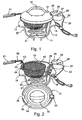
- the cooking appliance illustrated in Figs. 1 - 4 includes a receptacle, generally designated 10, having a bottom wall 11, a side wall 12, and an open top defined by the upper rim 13 of the side wall, for receiving food articles such as potato sticks or slices to be deep-fried, and a quantity of oil for deep-frying the food articles.
- receptacle 10 is made of a transparent material to permit viewing the food articles therein.
- the upper rim 13 of receptacle 10 is provided with a pair of finger grips 14 to facilitate handling the receptacle; and the bottom wall 11 is provided with a plurality of feet 15 to permit the receptacle to be supported on a flat horizontal surface.
- the illustrated cooking appliance further includes two electrical heater bodies.
- One electrical body, generally designated 20, includes a heater coil 21 to be disposed within the receptacle 10 adjacent to its bottom wall 11 so as to be immersed within the frying oil.
- the other electrical heater body 30 is disposed within a lid 31 removably receivable over the open top of the receptacle, as described more particularly below.
- the lower electrical heater body 20 further includes a housing 22 connectable by an electrical cable 23 to a power supply outlet for supplying electrical power to the heater coil 21 via a vertically-extending conduit 24.
- the lower electrical heater body 20 is a separate unit removably attachable to the receptacle 10 by resting the juncture between the housing 22 and the vertically-extending conduit 24 on the rim 13 of the receptacle side wall 12.
- Housing 22 of the lower electrical heater body 20 further includes a horizontally-extending socket 25 for electrically connecting the upper electrical heater body 30 within the lid 31, to the electrical power supply via cable 23.
- Housing 22 further includes On/Off switches 26 and 27 for selectively supplying electrical power to the lower electrical heater body 20 and to the upper electrical heater body 30 within the lid 31, as will be described more particularly below.
- a light indicator 28, 29 is provided adjacent each switch 26, 27, to indicate whether its respective electrical heater body is energized.
- lid 31 is formed as a heat-reflector surface 34 for reflecting the heat from the upper electrical heater body 30 into the interior of the receptacle 10.
- Reflector 34 is also of annular configuration, and the central region 35 of the lid is transparent to permit the interior of the receptacle to be viewed through the lid when applied over the receptacle.
- Lid 31 is further formed with a slot 36 at one side for accommodating the article holder 40, as described below.
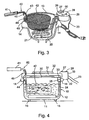
- Article holder 40 is formed with a handle 41 at one end, and an oil-permeable wire basket 42 at the opposite end for receiving the food articles, e.g., potato sticks, to be fried.
- a downwardly-bent juncture portion 43 between handle 41 and the wire basket 42 is formed with a lower hook 44 engageable with the rim 13 of the receptacle 10 for supporting the wire basket 42 elevated above the quantity of oil in receptacle 10 as shown in Fig. 3, and an upper hook 45 for supporting the wire basket in a lower position immersed within the oil in the receptacle as shown in Fig. 4.
- the cooking appliance illustrated in Figs. 1- 4 is used in the following manner:
- the frying oil is poured into the receptacle 10 to a level as shown in Fig. 4, and is heated to the frying temperature by energizing the lower electrical heater body 20. If accelerated heating is desired, the lid 31 may be applied over the open end of the receptacle, with its plug 33 received within socket 25 of the lower electrical heater body 20 to energize also the upper electrical body 30 within the lid.
- the lid 31 is removed, and the freshly-cut food articles to be fried, e.g., potato sticks, are received within basket 42 of the article holder 40.
- the article holder 40 is then applied with its lower hook 44 received over the rim 13 of the receptacle 10 to thereby space the wire basket, and the potato sticks therein, slightly above the hot oil within the receptacle 10 for pre-heating the potato sticks, and also for partially drying the moist surfaces of the freshly-cut potato sticks.
- the article holder 40 is then moved to apply the upper hook 45 over the rim 13 of the receptacle 10, to immerse the wire basket 42, and the potato sticks therein, within the hot oil in the receptacle for deep-frying the potato sticks.
- lid 31 may be re-applied over the upper end of the receptacle with plug 33 of the lid received within socket 25 of the lower electrical heater body 20, to thereby enable energizing also the upper electrical heater body 30 within the lid by depressing both switches 26 and 27.
- lid 31 is removed with its upper heater body 30, and the wire basket is raised with its lower hook 44 again applied over rim 13 of the receptacle, such that the potato sticks within the wire basket 42 are again supported spaced above the hot frying oil within the receptacle to permit draining of the oil from the potato sticks back into the receptacle.
- the fried potato sticks may then be removed from the wire basket 42.
- the cooking appliance illustrated in Figs. 1- 4 may thus be used to deep-fry potato sticks or other food articles in a much shorter period of time than in a conventional appliance.
- the pre-heating of the food articles, and the partial drying of the outer surfaces of the food articles before immersing them into the hot oil have been found to significantly enhance the crispiness of the fried articles and also to significantly reduce the amount of oil absorbed by the fried articles. Both of the above results are very desirable for taste and health purposes.
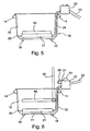
- Fig. 5 illustrates the cooking appliance of Figs. 1 - 4 as further including a removable heat-resistant plate 50 supported on coil 21 of the lower electrical heater body 20 within the receptacle 10.
- a removable heat-resistant plate 50 supported on coil 21 of the lower electrical heater body 20 within the receptacle 10.
- the provision of such a heat-resistant plate 50 enables the cooking appliance also to receive another receptacle for boiling food articles in the other receptacle.
- the cooking appliance illustrated in Fig. 5 is otherwise the same as described above with respect to Figs. 1 - 4, and therefore its various parts are identified by the same reference numerals.
- Fig. 6 schematically illustrates another embodiment of the invention wherein the upper electrical heater body, instead of being mounted within and removable with the removable lid 31, is pivotally mounted within the receptacle.
- the upper electrical heater body, therein designated 60 is pivotally mounted within receptacle 10 to an operative position, shown in full lines, wherein it is oriented to extend horizontally parallel to and spaced above the heater coil 21 of the lower electrical heater body 20, or to an inoperative position, shown in broken lines, wherein it is oriented to extend vertically through the open top of the receptacle.
- the housing 22 for the lower electrical heater body 20 is provided with a rotary knob 61 coupled in any suitable manner, e.g., by a gear coupling (not shown), such that rotation of the knob in one direction pivots the upper electrical heater body 60 to its operative horizontal position, and rotating the knob in the opposite direction pivots the upper electrical heater body 60 to its vertical inoperative position.
- Housing 22 also includes the electrical switches 26, 27 for selectively energizing the two electrical heater bodies 20, 60. It may also include an interlock which permits pivoting the upper electrical heater body to its vertical inoperative position only when it is de-energized.
- the electrical heater illustrated in Fig. 6 may be constructed and used in the same manner as described above with respect to Figs. 1-4 and Fig. 5.
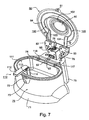
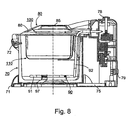
- Fig. 7 - 11 illustrate a further cooking appliance constructed in accordance with the present invention, also including a receptacle, generally designated 70; a lid 80 overlying the open top of the receptacle; a lower electrical heater body 90 at the bottom of the receptacle; an upper electrical heater body 100 carried by the inner face of the lid; and a food article holder 110 for holding the food articles, e.g., potato sticks, to be fried.
- lid 80 together with the upper electrical heater body 100 carried by the lid, is pivotally mounted to the upper end of receptacle 70.
- receptacle 70 is mounted on a base 71 for spacing the bottom of the receptacle above the supporting surface.
- Receptacle 70 is preferably made of metal and removably supported on base 71.
- receptacle 70 The upper open end of receptacle 70 is provided with a retainer socket 72 for receiving a leaf spring retainer 81 carried by the lid 80 in order to retain the lid in its closed position over the upper end of the container as shown in Fig. 8.
- Socket 72 includes a release button 73 which, when depressed, releases retainer 81 from the socket to permit the lid to pivot to its open position, as shown in Fig. 7.
- Receptacle 70 includes an inner pot 74 for receiving the oil to be used in frying the food articles.
- Receptacle 70 is formed with a spine section 75 at the side thereof opposite to that of its retainer socket 72, for pivotally mounting lid 80 about an axis 76 at the upper end of the spine section 75.
- the upper end of spine section 76 further carries a housing 77 for one or more electrical controls, e.g., a temperature control knob 78.
- the appliance on/off switch is preferably carried on the outer wall of the spine section 75, as shown at 79 in Fig. 8.
- Lid 80 is pivotally mounted to receptacle 70 about pivot axis 76 by a pair of arms 82, 83 straddling electrical housing 77 at the upper end of the receptacle spine section 75.
- the inner face of lid 80 carries a reflector 84 for reflecting the heat generated by the upper electrical heater 100 into the receptacle 70 when the lid is pivoted to its closed position as shown in Fig. 8.
- the central section 85 of lid 80 is preferably made of transparent glass to permit viewing the interior of the receptacle when the lid is closed.
- the lower electrical heater body 90 located within receptacle 70, more particularly at the bottom of the oil pot 74 as shown in Fig. 8, is best seen in Fig. 9. It includes a sinuous coil 91 connected at its opposite ends by a pair of conductor rods 92, 93 to the electrical connections within the spine section 75 of receptacle 70. Spine section 75 may include a removable panel 94 to provide access to the electrical elements within that section.
- the upper end of spine section 75 includes, in addition to the temperature control knob 78, also an indicator lamp 95 to indicate when the lower electrical heater body 90 is energized.
- the lower end of spine section 74 carries a pair of connector terminals 96 for providing electrical connection to the upper electrical heater body 100 carried by the lid 80.
- the sinuous coil 91 of the lower electrical heater body 90 is secured within pot 74 by a clip 97.
- the upper electrical heater body 100 includes an electrical coil 101 secured to the inner face of reflector 84 by one or more clips 102.
- Coil 101 is connected to the electrical power supply via a pair of parallel conductor rods 103, 104 passing through the two arms 82, 83 into engagement with the connector terminals 96 at the lower end of the receptacle spine section 75.
- the food article holder generally designated 110, is best seen in Figs. 10 and 11. It includes an oil permeable basket 111 for holding food articles to be fried, and basket supporting means for selectively supporting the basket either in an upper position spaced over the quantity of oil within the receptacle, or in a lower position immersing the basket and the food articles therein within the quantity of oil, as described above with respect to Fig. 4.
- basket supporting means for selectively supporting the basket either in an upper position spaced over the quantity of oil within the receptacle, or in a lower position immersing the basket and the food articles therein within the quantity of oil, as described above with respect to Fig. 4.
- a different arrangement is used instead of providing two hooks (44, 45, Fig. 4) for this purpose.
- the food article holder 110 includes, in addition to the wire basket 111, a handle 112 quickly-detachable from the food basket 111.
- handle 112 When handle 112 is attached, it enables manipulating the basket as well supporting the basket in its lower position immersed within the oil in the receptacle.
- handle 112 When detached from the wire basket, it enables the lid 80 to be pivotted to its fully closed position over the receptacle.
- Handle 112 includes a pair of depending spring arms 113, 114, each formed at its outer end with a pair of out-turned steps 113a, 113b and 114a, 114b, respectively.
- the inner surface of wire basket 111 is formed with a first pair of closely-spaced tabs 115 receiving the two arms 113, 114 and their respective out-turned steps 113a, 114a, and another pair of more widely-spaced tabs 116 for receiving the outer ends of the two arms and the respective out-turned steps 113b, 114b, as shown in Fig. 11.
- handle 112 may be quickly attached to the wire basket 111 by squeezing the two arms 113, 114 towards each other and inserting them between the two pairs of tabs 115, 116; it may be quickly detached from the wire basket by again squeezing the two arms towards each other and removing them from the tabs.
- the opposite side of basket 111 is formed with a pair of outwardly-extending wire hooks 117, 118, for mounting the basket within the oil pot 74 in receptacle 70.
- This may be conveniently done by applying the hooks over the upper end of the rim of the oil pot, or receptacle.
- that side of the oil pot 74, as well as of the receptacle 70, is flattened to accommodate spine section 75 as well as the hooks 117, 118 of the wire basket 111.
- the manner of using the cooking appliance illustrated in Figs. 7 - 11 will be apparent from the above description. Assuming that the oil pot 74 contains the appropriate quantity of oil, the lower electrical heater body 90 may be energized to heat the oil. If accelerated heating is desired, lid 80 may be pivotted to its closed position and the upper electrical heater body 100 may also be energized.
- the freshly-cut food articles to be fried are placed within the wire basket 111 while the handle 112 is attached; lid 80 is pivotted to its open position: and the wire basket is then moved to the upper end of the oil pot 74 and hooked thereon by the hooks 117, 118.
- the hooks 117, 118 are so located with respect to the oil pot so as to support the basket in its upper position above the hot oil within the oil pot.
- the hot oil within the oil pot pre-heats the food articles and also partially dries their outer surfaces if moist because of having been freshly-cut, e.g., in the case of potato sticks or slices. If desired, this pre-heating may be effected with the handle 112 removed and the lid closed.
- handle 112 is re-attached to basked 111 (if previously removed), and the basket is lowered into the oil within the oil pot 74 until the handle 112 limits against the upper rim of the oil pot or of the receptacle 70. In this lowered position of the basket, it is immersed within the oil in the oil pot for deep-frying the articles in the basket. If accelerated frying is desired, the lid 80 may pivotted to its closed position and the upper electrical heater body 100 energized.
- handle 112 may be used for raising the basket 111 out of the oil and attaching clips 117, 118 of the basket to the rim of the oil pot or receptacle, to enable drainage of the oil from the articles within the basket.
- the fried food articles may then be removed from the basket.
Landscapes
- Engineering & Computer Science (AREA)
- Food Science & Technology (AREA)
- Frying-Pans Or Fryers (AREA)
- General Preparation And Processing Of Foods (AREA)
- Manufacture And Refinement Of Metals (AREA)
- Cookers (AREA)
Claims (16)
- Appareil de cuisson particulièrement adapté à la grande friture d'aliments, comprenant : un réceptacle (10) ayant une paroi inférieure (11), une paroi latérale (12) et une partie supérieure ouverte (13) pour recevoir des aliments et une quantité d'huile pour la grande friture des aliments à l'intérieur de celui-ci ; un corps de chauffage électrique inférieur (20) à l'intérieur dudit réceptacle (10) adjacent à sa paroi inférieure (11) pour une immersion dans ladite quantité d'huile lorsqu'il est logé dans ledit réceptacle, caractérisé en ce qu'il comprend en outre un corps de chauffage électrique supérieur (30) pouvant se déplacer par rapport audit réceptacle, et audit corps de chauffage électrique inférieur à l'intérieur de celui-ci, vers (a) une position inopérationnelle permettant l'introduction et le retrait d'aliments via ladite partie supérieure ouverte ; et (b) une position opérationnelle espacée au-dessus dudit corps de chauffage électrique inférieur (20) pour permettre un chauffage accéléré de la quantité d'huile lorsqu'il est logé à l'intérieur du réceptacle.
- Appareil de cuisson selon la revendication 1, dans lequel ledit corps de chauffage électrique inférieur est disposé horizontalement au-dessus de ladite paroi inférieure du réceptacle ; et dans lequel ledit appareil de cuisson comprend en outre une plaque amovible résistant à la chaleur supportée par ledit corps de chauffage électrique inférieur pour permettre à l'appareil de cuisson de recevoir un autre réceptacle pour cuire des aliments à l'intérieur de celui-ci.
- Appareil de cuisson selon la revendication 1 ou 2, dans lequel l'appareil de cuisson comprend en outre un couvercle pouvant bouger de manière sélective pour couvrir ou découvrir ladite partie supérieure ouverte du réceptacle, ledit corps de chauffage électrique supérieur étant porté par ledit couvercle et étant déplaçable avec celui-ci vers ladite position inopérationnelle du corps de chauffage électrique supérieur.
- Appareil de cuisson selon la revendication 3, dans lequel ledit couvercle est monté de manière amovible sur la partie supérieure ouverte dudit réceptacle et comprend en outre une fiche électrique pouvant être logée dans une prise de courant portée par ledit réceptacle pour alimenter en énergie ledit corps de chauffage électrique supérieur lorsque le couvercle est posé sur la partie supérieure ouverte dudit réceptacle.
- Appareil de cuisson selon la revendication 4, dans lequel ledit corps de chauffage électrique inférieur est sous la forme d'une unité séparée logée de manière amovible sur le bord supérieur de la paroi latérale du réceptacle et comprend ladite prise de courant pour recevoir ladite fiche dans ledit couvercle.
- Appareil de cuisson selon la revendication 3, dans lequel ledit couvercle est monté de manière pivotante sur la partie supérieure ouverte dudit réceptacle.
- Appareil de cuisson selon la revendication 3, dans lequel ledit couvercle comprend en outre un réflecteur assistant ledit corps de chauffage électrique supérieur pour refléter la chaleur à partir de celui-ci dans ledit réceptacle lorsque le corps de chauffage électrique supérieur est alimenté en énergie.
- Appareil de cuisson selon la revendication 7, dans lequel ledit corps de chauffage électrique supérieur et ledit réflecteur sont d'une configuration annulaire, et ledit couvercle comprend une section transparente à la lumière au centre dudit corps de chauffage électrique supérieur et du réflecteur pour permettre de voir les contenus du réceptacle lorsque le couvercle recouvre la partie supérieure ouverte du réceptacle.
- Appareil de cuisson selon la revendication 1 ou 2, dans lequel l'appareil de cuisson comprend en outre un récipient d'aliments comprenant un panier perméable à l'huile pour contenir les aliments à frire, et des moyens de support de panier pour supporter de manière sélective ledit panier soit dans une position supérieure espacée au-dessus de la quantité d'huile dans le réceptacle, soit dans une position inférieure immergeant le panier et les aliments à l'intérieur de celui-ci dans la quantité d'huile.
- Appareil de cuisson selon la revendication 9, dans lequel lesdits moyens de support de panier comprennent:une poignée pour manipuler manuellement ledit panier ;un crochet inférieur porté par ladite poignée pour supporter le panier dans ladite position supérieure au-dessus de ladite quantité d'huile pour préchauffer les aliments dans le panier avant d'immerger le panier et les aliments à l'intérieur de celui-ci dans la quantité d'huile ; etun crochet supérieur porté par ladite poignée pour supporter le panier dans ladite position inférieure immergeant le panier et les aliments à l'intérieur de celui-ci dans la quantité d'huile dans le réceptacle.
- Appareil de cuisson selon la revendication 1, dans lequel ledit corps de chauffage électrique supérieur est monté de manière pivotante à l'intérieur dudit réceptacle vers ladite position opérationnelle dans laquelle il est orienté pour s'étendre horizontalement de manière parallèle par rapport audit corps de chauffage électrique inférieur et en étant espacé au-dessus de celui-ci, ou vers la position inopérationnelle dans laquelle il est orienté pour s'étendre verticalement à travers la partie supérieure ouverte dudit réceptacle.
- Appareil de cuisson selon la revendication 11, dans lequel l'appareil de cuisson comprend un opérateur manuel pour pivoter manuellement ledit corps de chauffage électrique supérieur vers ladite position opérationnelle horizontale ou vers ladite position inopérationnelle verticale.
- Appareil de cuisson selon la revendication 11, dans lequel ledit corps de chauffage électrique inférieur est sous la forme d'une unité séparée logée de manière amovible sur le bord supérieur de la paroi latérale du réceptacle et comprend aussi ledit corps de chauffage électrique supérieur pivotant.
- Appareil de cuisson selon la revendication 9 ou 14, dans lequel lesdits moyens de support de panier comprennent une poignée pour manipuler manuellement ledit panier, ladite poignée étant dimensionnée de manière à pouvoir entrer en prise avec la partie supérieure ouverte dudit réceptacle pour supporter ledit panier dans ladite position inférieure ; lesdits moyens de support de panier comprenant en outre une ou plusieurs attaches portées par ledit panier pouvant entrer en prise avec la partie supérieure ouverte dudit réceptacle pour supporter ledit panier dans ladite position supérieure.
- Appareil de cuisson selon la revendication 15, dans lequel ladite poignée comprend une paire de bras à ressort pouvant entrer en prise avec une paire d'épaulements espacés portés par ledit récipient d' aliments pour fixer ou détacher de manière sélective ladite poignée dudit récipient d'aliments.
- Procédé de grande friture d'aliments, en particulier de pommes de terre, utilisant l'appareil de la revendication 1, comprenant les étapes consistant à :verser de l'huile de friture dans le réceptacle ;chauffer à la température de friture en alimentant en énergie le corps de chauffage électrique inférieur ;disposer lesdits aliments dans le panier perméable à l'huile ;déplacer le corps de chauffage électrique supérieur vers la position inopérationnelle ;suspendre ledit panier et les aliments à l'intérieur de celui-ci au-dessus de l'huile de friture brûlante pour préchauffer lesdits aliments et partiellement sécher leurs surfaces extérieures ; etabaisser ensuite ledit panier pour immerger lesdits aliments dans ladite huile brûlante, pour produire ainsi des aliments frits ayant un croustillant renforcé et une absorption d'huile réduite.
Applications Claiming Priority (3)
| Application Number | Priority Date | Filing Date | Title |
|---|---|---|---|
| US37142902P | 2002-04-11 | 2002-04-11 | |
| US371429P | 2002-04-11 | ||
| PCT/IL2003/000258 WO2003086156A2 (fr) | 2002-04-11 | 2003-03-27 | Appareil de cuisson et procede particulierement adapte a la grande friture d'aliments |
Publications (3)
| Publication Number | Publication Date |
|---|---|
| EP1492436A2 EP1492436A2 (fr) | 2005-01-05 |
| EP1492436A4 EP1492436A4 (fr) | 2005-10-12 |
| EP1492436B1 true EP1492436B1 (fr) | 2006-06-21 |
Family
ID=29250677
Family Applications (1)
| Application Number | Title | Priority Date | Filing Date |
|---|---|---|---|
| EP03715293A Expired - Lifetime EP1492436B1 (fr) | 2002-04-11 | 2003-03-27 | Appareil de cuisson et procede particulierement adapte a la grande friture d'aliments |
Country Status (5)
| Country | Link |
|---|---|
| EP (1) | EP1492436B1 (fr) |
| AT (1) | ATE330518T1 (fr) |
| AU (1) | AU2003219481A1 (fr) |
| DE (1) | DE60306350T2 (fr) |
| WO (1) | WO2003086156A2 (fr) |
Families Citing this family (3)
| Publication number | Priority date | Publication date | Assignee | Title |
|---|---|---|---|---|
| EP2133013B1 (fr) * | 2008-06-10 | 2011-01-26 | Whirlpool Corporation | Appareil de cuisson multifonction |
| CN114269035B (zh) * | 2021-12-10 | 2024-08-09 | 广东美的厨房电器制造有限公司 | 烹饪设备 |
| CN114245506B (zh) * | 2021-12-10 | 2024-08-20 | 广东美的厨房电器制造有限公司 | 烹饪设备 |
Family Cites Families (7)
| Publication number | Priority date | Publication date | Assignee | Title |
|---|---|---|---|---|
| DE6812665U (de) * | 1968-12-21 | 1969-05-14 | Senkingwerk K G | Elektrisch beheizte kippbratpfanne |
| US3613553A (en) * | 1969-07-14 | 1971-10-19 | Popeil Brothers | Apparatus for puffed potato product |
| FR2507398B1 (fr) * | 1981-06-04 | 1983-11-18 | Dietrich & Cie De | |
| US4444095A (en) * | 1982-02-12 | 1984-04-24 | Anetsberger Brothers, Inc. | Deep fat fryer system |
| US6058245A (en) * | 1998-08-05 | 2000-05-02 | Afc Enterprises, Inc. | Electric boost heater for deep fryer |
| KR200214880Y1 (ko) * | 2000-08-26 | 2001-02-15 | 송영주 | 다용도 튀김기 |
| US6453801B1 (en) * | 2001-01-17 | 2002-09-24 | Ruben Masel | Appliance for cooking food articles |
-
2003
- 2003-03-27 WO PCT/IL2003/000258 patent/WO2003086156A2/fr not_active Ceased
- 2003-03-27 AT AT03715293T patent/ATE330518T1/de not_active IP Right Cessation
- 2003-03-27 DE DE60306350T patent/DE60306350T2/de not_active Expired - Lifetime
- 2003-03-27 EP EP03715293A patent/EP1492436B1/fr not_active Expired - Lifetime
- 2003-03-27 AU AU2003219481A patent/AU2003219481A1/en not_active Abandoned
Also Published As
| Publication number | Publication date |
|---|---|
| EP1492436A2 (fr) | 2005-01-05 |
| AU2003219481A8 (en) | 2003-10-27 |
| DE60306350D1 (de) | 2006-08-03 |
| DE60306350T2 (de) | 2007-05-10 |
| HK1073415A1 (en) | 2005-10-07 |
| ATE330518T1 (de) | 2006-07-15 |
| AU2003219481A1 (en) | 2003-10-27 |
| WO2003086156A2 (fr) | 2003-10-23 |
| EP1492436A4 (fr) | 2005-10-12 |
| WO2003086156A3 (fr) | 2003-12-31 |
Similar Documents
| Publication | Publication Date | Title |
|---|---|---|
| US5758569A (en) | Poultry frying apparatus | |
| US8707857B2 (en) | Cooking device to deep fat fry foods | |
| US2215929A (en) | Cooking machine | |
| US4295034A (en) | Hot air grill | |
| CA2434624C (fr) | Appareil et procede servant a cuisiner des produits alimentaires | |
| NL9302217A (nl) | Hoge temperatuur adiabatisch kookapparaat. | |
| AU747736B2 (en) | Cooking appliance and method particularly useful for frying or steaming food | |
| US7067778B2 (en) | Microwaveable cooking container and microwave oven | |
| US4773316A (en) | Method of frying food and apparatus for the practice thereof | |
| US6062132A (en) | Cooking apparatus | |
| US2157303A (en) | Draining frying pan | |
| WO2003086156A2 (fr) | Appareil de cuisson et procede particulierement adapte a la grande friture d'aliments | |
| HK1073415B (en) | Cooking appliance and method particularly useful for deep-frying food articles | |
| US3691935A (en) | Broiler | |
| US6382085B1 (en) | Cooking appliance particularly useful as a multi-function toaster oven | |
| KR19980015002A (ko) | 전자유도가열튀김기의 균일튀김장치 | |
| JP2003524495A (ja) | 殻無し卵調理装置 | |
| FI56484C (fi) | Grill | |
| US3677170A (en) | Pressure cooking apparatus | |
| CA2401446C (fr) | Appareil electrique pour la cuisson des oeufs | |
| CN216020415U (zh) | 一种砂锅加热自动上菜装置 | |
| KR20050043527A (ko) | 할로겐히터를 구비한 조리기 | |
| CN114983254A (zh) | 烹饪用具 | |
| JPS62144621A (ja) | 電気調理器 | |
| CZ32858U1 (cs) | Zařízení pro tepelnou úpravu potravin |
Legal Events
| Date | Code | Title | Description |
|---|---|---|---|
| PUAI | Public reference made under article 153(3) epc to a published international application that has entered the european phase |
Free format text: ORIGINAL CODE: 0009012 |
|
| 17P | Request for examination filed |
Effective date: 20041008 |
|
| AK | Designated contracting states |
Kind code of ref document: A2 Designated state(s): AT BE BG CH CY CZ DE DK EE ES FI FR GB GR HU IE IT LI LU MC NL PT RO SE SI SK TR |
|
| AX | Request for extension of the european patent |
Extension state: AL LT LV MK |
|
| REG | Reference to a national code |
Ref country code: HK Ref legal event code: DE Ref document number: 1073415 Country of ref document: HK |
|
| A4 | Supplementary search report drawn up and despatched |
Effective date: 20050830 |
|
| GRAP | Despatch of communication of intention to grant a patent |
Free format text: ORIGINAL CODE: EPIDOSNIGR1 |
|
| GRAS | Grant fee paid |
Free format text: ORIGINAL CODE: EPIDOSNIGR3 |
|
| GRAA | (expected) grant |
Free format text: ORIGINAL CODE: 0009210 |
|
| AK | Designated contracting states |
Kind code of ref document: B1 Designated state(s): AT BE BG CH CY CZ DE DK EE ES FI FR GB GR HU IE IT LI LU MC NL PT RO SE SI SK TR |
|
| PG25 | Lapsed in a contracting state [announced via postgrant information from national office to epo] |
Ref country code: IT Free format text: LAPSE BECAUSE OF FAILURE TO SUBMIT A TRANSLATION OF THE DESCRIPTION OR TO PAY THE FEE WITHIN THE PRESCRIBED TIME-LIMIT;WARNING: LAPSES OF ITALIAN PATENTS WITH EFFECTIVE DATE BEFORE 2007 MAY HAVE OCCURRED AT ANY TIME BEFORE 2007. THE CORRECT EFFECTIVE DATE MAY BE DIFFERENT FROM THE ONE RECORDED. Effective date: 20060621 Ref country code: NL Free format text: LAPSE BECAUSE OF FAILURE TO SUBMIT A TRANSLATION OF THE DESCRIPTION OR TO PAY THE FEE WITHIN THE PRESCRIBED TIME-LIMIT Effective date: 20060621 Ref country code: AT Free format text: LAPSE BECAUSE OF FAILURE TO SUBMIT A TRANSLATION OF THE DESCRIPTION OR TO PAY THE FEE WITHIN THE PRESCRIBED TIME-LIMIT Effective date: 20060621 Ref country code: RO Free format text: LAPSE BECAUSE OF FAILURE TO SUBMIT A TRANSLATION OF THE DESCRIPTION OR TO PAY THE FEE WITHIN THE PRESCRIBED TIME-LIMIT Effective date: 20060621 Ref country code: SI Free format text: LAPSE BECAUSE OF FAILURE TO SUBMIT A TRANSLATION OF THE DESCRIPTION OR TO PAY THE FEE WITHIN THE PRESCRIBED TIME-LIMIT Effective date: 20060621 Ref country code: SK Free format text: LAPSE BECAUSE OF FAILURE TO SUBMIT A TRANSLATION OF THE DESCRIPTION OR TO PAY THE FEE WITHIN THE PRESCRIBED TIME-LIMIT Effective date: 20060621 Ref country code: LI Free format text: LAPSE BECAUSE OF FAILURE TO SUBMIT A TRANSLATION OF THE DESCRIPTION OR TO PAY THE FEE WITHIN THE PRESCRIBED TIME-LIMIT Effective date: 20060621 Ref country code: FI Free format text: LAPSE BECAUSE OF FAILURE TO SUBMIT A TRANSLATION OF THE DESCRIPTION OR TO PAY THE FEE WITHIN THE PRESCRIBED TIME-LIMIT Effective date: 20060621 Ref country code: BE Free format text: LAPSE BECAUSE OF FAILURE TO SUBMIT A TRANSLATION OF THE DESCRIPTION OR TO PAY THE FEE WITHIN THE PRESCRIBED TIME-LIMIT Effective date: 20060621 Ref country code: CH Free format text: LAPSE BECAUSE OF FAILURE TO SUBMIT A TRANSLATION OF THE DESCRIPTION OR TO PAY THE FEE WITHIN THE PRESCRIBED TIME-LIMIT Effective date: 20060621 Ref country code: CZ Free format text: LAPSE BECAUSE OF FAILURE TO SUBMIT A TRANSLATION OF THE DESCRIPTION OR TO PAY THE FEE WITHIN THE PRESCRIBED TIME-LIMIT Effective date: 20060621 |
|
| REG | Reference to a national code |
Ref country code: GB Ref legal event code: FG4D |
|
| REG | Reference to a national code |
Ref country code: CH Ref legal event code: EP |
|
| REG | Reference to a national code |
Ref country code: IE Ref legal event code: FG4D |
|
| REF | Corresponds to: |
Ref document number: 60306350 Country of ref document: DE Date of ref document: 20060803 Kind code of ref document: P |
|
| PG25 | Lapsed in a contracting state [announced via postgrant information from national office to epo] |
Ref country code: SE Free format text: LAPSE BECAUSE OF FAILURE TO SUBMIT A TRANSLATION OF THE DESCRIPTION OR TO PAY THE FEE WITHIN THE PRESCRIBED TIME-LIMIT Effective date: 20060921 Ref country code: DK Free format text: LAPSE BECAUSE OF FAILURE TO SUBMIT A TRANSLATION OF THE DESCRIPTION OR TO PAY THE FEE WITHIN THE PRESCRIBED TIME-LIMIT Effective date: 20060921 |
|
| REG | Reference to a national code |
Ref country code: HK Ref legal event code: GR Ref document number: 1073415 Country of ref document: HK |
|
| PG25 | Lapsed in a contracting state [announced via postgrant information from national office to epo] |
Ref country code: ES Free format text: LAPSE BECAUSE OF FAILURE TO SUBMIT A TRANSLATION OF THE DESCRIPTION OR TO PAY THE FEE WITHIN THE PRESCRIBED TIME-LIMIT Effective date: 20061002 |
|
| PG25 | Lapsed in a contracting state [announced via postgrant information from national office to epo] |
Ref country code: PT Free format text: LAPSE BECAUSE OF FAILURE TO SUBMIT A TRANSLATION OF THE DESCRIPTION OR TO PAY THE FEE WITHIN THE PRESCRIBED TIME-LIMIT Effective date: 20061121 |
|
| ET | Fr: translation filed | ||
| NLV1 | Nl: lapsed or annulled due to failure to fulfill the requirements of art. 29p and 29m of the patents act | ||
| REG | Reference to a national code |
Ref country code: CH Ref legal event code: PL |
|
| PLBE | No opposition filed within time limit |
Free format text: ORIGINAL CODE: 0009261 |
|
| STAA | Information on the status of an ep patent application or granted ep patent |
Free format text: STATUS: NO OPPOSITION FILED WITHIN TIME LIMIT |
|
| 26N | No opposition filed |
Effective date: 20070322 |
|
| PG25 | Lapsed in a contracting state [announced via postgrant information from national office to epo] |
Ref country code: MC Free format text: LAPSE BECAUSE OF NON-PAYMENT OF DUE FEES Effective date: 20070331 Ref country code: IE Free format text: LAPSE BECAUSE OF NON-PAYMENT OF DUE FEES Effective date: 20070327 |
|
| PG25 | Lapsed in a contracting state [announced via postgrant information from national office to epo] |
Ref country code: GR Free format text: LAPSE BECAUSE OF FAILURE TO SUBMIT A TRANSLATION OF THE DESCRIPTION OR TO PAY THE FEE WITHIN THE PRESCRIBED TIME-LIMIT Effective date: 20060922 |
|
| PG25 | Lapsed in a contracting state [announced via postgrant information from national office to epo] |
Ref country code: BG Free format text: LAPSE BECAUSE OF FAILURE TO SUBMIT A TRANSLATION OF THE DESCRIPTION OR TO PAY THE FEE WITHIN THE PRESCRIBED TIME-LIMIT Effective date: 20060921 |
|
| PG25 | Lapsed in a contracting state [announced via postgrant information from national office to epo] |
Ref country code: EE Free format text: LAPSE BECAUSE OF FAILURE TO SUBMIT A TRANSLATION OF THE DESCRIPTION OR TO PAY THE FEE WITHIN THE PRESCRIBED TIME-LIMIT Effective date: 20060621 |
|
| PG25 | Lapsed in a contracting state [announced via postgrant information from national office to epo] |
Ref country code: CY Free format text: LAPSE BECAUSE OF FAILURE TO SUBMIT A TRANSLATION OF THE DESCRIPTION OR TO PAY THE FEE WITHIN THE PRESCRIBED TIME-LIMIT Effective date: 20060621 Ref country code: LU Free format text: LAPSE BECAUSE OF NON-PAYMENT OF DUE FEES Effective date: 20070327 |
|
| PG25 | Lapsed in a contracting state [announced via postgrant information from national office to epo] |
Ref country code: HU Free format text: LAPSE BECAUSE OF FAILURE TO SUBMIT A TRANSLATION OF THE DESCRIPTION OR TO PAY THE FEE WITHIN THE PRESCRIBED TIME-LIMIT Effective date: 20061222 Ref country code: TR Free format text: LAPSE BECAUSE OF FAILURE TO SUBMIT A TRANSLATION OF THE DESCRIPTION OR TO PAY THE FEE WITHIN THE PRESCRIBED TIME-LIMIT Effective date: 20060621 |
|
| PGFP | Annual fee paid to national office [announced via postgrant information from national office to epo] |
Ref country code: FR Payment date: 20110414 Year of fee payment: 9 Ref country code: DE Payment date: 20110329 Year of fee payment: 9 Ref country code: GB Payment date: 20110325 Year of fee payment: 9 |
|
| GBPC | Gb: european patent ceased through non-payment of renewal fee |
Effective date: 20120327 |
|
| REG | Reference to a national code |
Ref country code: FR Ref legal event code: ST Effective date: 20121130 |
|
| REG | Reference to a national code |
Ref country code: DE Ref legal event code: R119 Ref document number: 60306350 Country of ref document: DE Effective date: 20121002 |
|
| PG25 | Lapsed in a contracting state [announced via postgrant information from national office to epo] |
Ref country code: FR Free format text: LAPSE BECAUSE OF NON-PAYMENT OF DUE FEES Effective date: 20120402 Ref country code: GB Free format text: LAPSE BECAUSE OF NON-PAYMENT OF DUE FEES Effective date: 20120327 |
|
| PG25 | Lapsed in a contracting state [announced via postgrant information from national office to epo] |
Ref country code: DE Free format text: LAPSE BECAUSE OF NON-PAYMENT OF DUE FEES Effective date: 20121002 |