EP1492696B1 - Vorrichtung zur befestigung eines fahrradschutzblechs mit zwei miteinander verbundenen elementen - Google Patents
Vorrichtung zur befestigung eines fahrradschutzblechs mit zwei miteinander verbundenen elementen Download PDFInfo
- Publication number
- EP1492696B1 EP1492696B1 EP02798029A EP02798029A EP1492696B1 EP 1492696 B1 EP1492696 B1 EP 1492696B1 EP 02798029 A EP02798029 A EP 02798029A EP 02798029 A EP02798029 A EP 02798029A EP 1492696 B1 EP1492696 B1 EP 1492696B1
- Authority
- EP
- European Patent Office
- Prior art keywords
- clamping device
- mudguard
- anyone
- hole
- chamber
- Prior art date
- Legal status (The legal status is an assumption and is not a legal conclusion. Google has not performed a legal analysis and makes no representation as to the accuracy of the status listed.)
- Expired - Lifetime
Links
- 238000010168 coupling process Methods 0.000 claims abstract description 14
- 238000005859 coupling reaction Methods 0.000 claims abstract description 14
- 230000008878 coupling Effects 0.000 claims abstract description 12
- 239000000463 material Substances 0.000 claims description 11
- 239000004033 plastic Substances 0.000 claims description 8
- 229920003023 plastic Polymers 0.000 claims description 8
- 238000010079 rubber tapping Methods 0.000 claims description 7
- 229920005549 butyl rubber Polymers 0.000 claims description 2
- 239000003086 colorant Substances 0.000 claims description 2
- 229920000915 polyvinyl chloride Polymers 0.000 claims description 2
- 239000004800 polyvinyl chloride Substances 0.000 claims description 2
- 229920006122 polyamide resin Polymers 0.000 claims 1
- 238000003780 insertion Methods 0.000 description 4
- 230000037431 insertion Effects 0.000 description 4
- 230000000694 effects Effects 0.000 description 2
- 230000007774 longterm Effects 0.000 description 2
- 238000004519 manufacturing process Methods 0.000 description 2
- 238000000465 moulding Methods 0.000 description 2
- 239000004677 Nylon Substances 0.000 description 1
- 230000009471 action Effects 0.000 description 1
- 238000010276 construction Methods 0.000 description 1
- 230000006378 damage Effects 0.000 description 1
- 230000001419 dependent effect Effects 0.000 description 1
- 238000000605 extraction Methods 0.000 description 1
- 238000005304 joining Methods 0.000 description 1
- 238000000034 method Methods 0.000 description 1
- 238000012986 modification Methods 0.000 description 1
- 230000004048 modification Effects 0.000 description 1
- 229920001778 nylon Polymers 0.000 description 1
- 238000002360 preparation method Methods 0.000 description 1
- 239000012780 transparent material Substances 0.000 description 1
Images

Classifications
-
- B—PERFORMING OPERATIONS; TRANSPORTING
- B62—LAND VEHICLES FOR TRAVELLING OTHERWISE THAN ON RAILS
- B62J—CYCLE SADDLES OR SEATS; AUXILIARY DEVICES OR ACCESSORIES SPECIALLY ADAPTED TO CYCLES AND NOT OTHERWISE PROVIDED FOR, e.g. ARTICLE CARRIERS OR CYCLE PROTECTORS
- B62J15/00—Mud-guards for wheels
- B62J15/02—Fastening means; Stays
Definitions
- This invention concerns a clamping device for a bicycle mudguard which is able to provide firm and long-term fixing of the mudguard to its support rods by means of two interconnecting elements which form a simple, economic and secure fixing solution both during assembly of the bicycle and during its use.
- This invention is particularly applicable in the bicycle and bicycle component manufacturing sector.
- the Italian patent application no. VI95A000076 in the name of the same applicant describes, for example, a clamping system consisting of a plastic support element with an appropriate groove in which the edge of the mudguard to be fixed is inserted.
- This element is also equipped with a pair of holes, designed for the insertion of a pair of support rods, and an additional hole positioned perpendicularly to the rod holes and in such a way as to come out inside the groove.
- the mudguard is held in position by means of a self-tapping screw inserted in this last hole. The tightening of this screw perforates the mudguard and fixes it to the support element.
- this device is equipped with a pair of rod insertion holes which are not aligned with the median axis, it is asymmetrical and in order to be assembled correctly respective right and left elements must be prepared, thus increasing the moulding and stock costs.
- the support element can be manufactured by using a single mould from which two separate parts are obtained, joined together at one end, like the valves of a shell, so that they can be clamped by fitting them together.
- the two parts are joined together by mechanical coupling means, such as for example a self-tapping screw inserted in a hole positioned transversely to the block which is not however involved with the groove designed for the positioning and clamping of the mudguard edge.
- mechanical coupling means such as for example a self-tapping screw inserted in a hole positioned transversely to the block which is not however involved with the groove designed for the positioning and clamping of the mudguard edge.
- the support element of the device described in VR98U000039 is also equipped with holes designed to house the mudguard support rods which are generally integral at their other end with the fork of the bicycle frame or with the wheel hub.
- the mudguard is only held in place by the hindrance created by the projection inside the groove, where this projection is made from the same .plastic material forming the block.
- This invention proposes to overcome the drawbacks and disadvantages typical of the known background art, and to therefore provide a clamping device by means of two adjacent and cooperating elements able to form, in a simple and economic way, a firm and long-term fixing solution of a bicycle mudguard to its respective support rods, covering their respective ends safely.
- This invention also proposes to provide a clamping device that forms a perfectly symmetrical system, in which the individual pieces can be used indifferently on the right or left of the mudguard, thereby considerably reducing the moulding and stock costs.
- a first element which presents a chamber designed to house the mudguard support rod, covering it like a cap and being long enough to allow longitudinal adjustment of the rod with respect to the device with a certain amount of play.
- This first element also presents a hole designed to house a screw, or any other mechanical coupling means, for example a self-tapping screw.
- the second element also presents a hole designed to house a screw or any other mechanical coupling means and aligned with the hole of the first element thus allowing, according to a particular embodiment, the fixing and connection of the two elements.
- this screw can also fix the mudguard housed in the groove, for example by perforating it.
- the clamping device according to this invention makes it possible to achieve optimum fixing of a bicycle mudguard to its support rods, and the non-removable cap-shape makes the system particularly safe and accident-proof both during assembly and during the use of the bicycle.
- This type of clamping does in fact ensure safe and firm positioning of the mudguard also in the event of accidental knocks.
- the reference number 10 indicates a clamping device for a bicycle mudguard according to this invention.
- the clamping device 10 consists of a first element 11 .adjacent to and cooperating with a second element 12. Both these elements are formed with a hole 13a and 13b, respectively, positioned on the same axis and designed to house a screw or any other mechanical coupling means, e.g. a self-tapping screw.
- this screw can also fix the mudguard housed in the groove 15 formed in the second element 12, e.g. by perforating it.
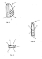
- the first element 11 as shown in figure 2 delimits a chamber 16. designed to house a support rod for the mudguard, by engaging it like a cap.
- the entry opening 17 to the chamber 16 is flared, thereby allowing easy insertion of the support rod into the chamber 16.
- chamber 16 according to this invention is long enough to make it possible for the support rod to be inserted vertically into it with a certain degree of play; this permits fine adjustment of the distance of the fixing device, and thus of the mudguard, with respect to the wheel hub.
- Both sides of the element 11 according to this invention is formed with convex circular slits or recesses 18, 18a, 18b around the hole 13a for housing, on one side, thereof the head of a screw or any other suitable fixing means, and on the other to allow cooperation with a circular part 19 of the second element shown in figures 6 and 8 .
- FIGS 3 and 4 also show the first element 11, in cross-section, according to the particular embodiment described.
- figure 3 shows the flared entry opening 17 for inserting the rod into the chamber 16
- figure 4 clearly shows the hole 13a through which the fixing means extends, and the slits 18a and 18b designed to cooperate in the fixing stage either with the outer part of the fixing means or with the protruding circular part .19 of the second element 12 forming a butt type joint.
- the second element 12 comprises a hole 13b designed to house a fixing means, e.g. a self-tapping screw, which extends through the groove 15 in which the edge of a mudguard is housed as shown in figure 8 .
- a fixing means e.g. a self-tapping screw
- the fixing means extending through the hole 13b and through the groove 15, can perforate the mudguard thereby fixing it firmly to the element 12, and more generally to the whole device 10 as well as to the rod connected to the wheel hub.
- the mudguard is formed with a hole for the insertion into it of the fixing means and its edge can engage, for example by means of a snap- or bayonet-coupling, with the element 12 thanks to the housing 20 for the edge of the mudguard as shown in figure 8 .
- An advantageous embodiment of the fixing system 10. envisages the construction of the two elements 11 and 12 with different types of plastic material that have technical features that are more suitable for carrying out the functions necessary to these elements 11 and 12.
- the element 11 can be made of soft and rubbery material such as butyl rubber or of nylon arranged to hold the rod inside the chamber 16 thanks to better gripping, whereas element 12 can be made of a relatively rigid material suitable for withstanding tearing stress, e.g. polyvinyl chloride.
- the device 10 can be constructed giving the elements 11 and 12 different colours such as, for example, by making the element 11, in view, of a transparent material and the element 12 connected to the mudguard of black plastic material, thus giving the invention a speficic esthetic effect.
- embodiments are envisaged whereby the first element that houses the rod is rotated with respect to the vertical, in the case in which the rod is fixed to a parcel-rack of the bicycle rather than to a hub.
- a further particularly advantageous embodiment of the invention envisages a cut in the first element 11 at the level of the lower edge of the expanded part presenting the hole 13a, which advantageously divides the expanded part of the first element 11 into two wings 21 which are arranged for example a few millimetres apart.
- the cut advantageously extends from the edge opposite to the chamber 16 to as far as the chamber 16 itself, internally following the circular slits 18a, 18b on the outside of the first element 11.
- the tightening action of the screw extending through the hole 13a thus acts, owing to the wings 21, also on the chamber 16 and consequently on the rod inserted in it, thereby preventing its extraction.
Landscapes
- Engineering & Computer Science (AREA)
- Mechanical Engineering (AREA)
- Axle Suspensions And Sidecars For Cycles (AREA)
- Steering Devices For Bicycles And Motorcycles (AREA)
Claims (13)
- Klemmvorrichtung für das Schutzblech eines Fahrrads, dadurch gekennzeichnet, dass sie aufweist: ein erstes Element (11), das mindestens eine im Wesentlichen geschlossene Kammer (16), die dazu bestimmt ist, das Ende eines Schutzblechhaltestabs aufzunehmen, und ein erstes Loch (13a) begrenzt, das dazu bestimmt ist, eine geeignete mechanische Kopplungseinrichtung aufzunehmen, und ein zweites Element (12), das dem ersten Element (11) benachbart ist und mit ihm zusammenarbeitet, das mit einer Nut (15), in der die Kante des Schutzblechs befestigt werden kann, und einem zweiten Loch (13b) ausgebildet ist, das dazu bestimmt ist, die mechanische Kopplungseinrichtung aufzunehmen, wobei das zweite Loch (13b) bezüglich des ersten Lochs (13a) des ersten Elements (11) ausgerichtet ist, wodurch die Verbindung des ersten Elements (11) mit dem zweiten Element (12) ermöglicht wird.
- Klemmvorrichtung nach Anspruch 1, dadurch gekennzeichnet, dass die Kammer (16) im ersten Element (11) lang genug ist, um eine longitudinale Feineinstellung der Position des Stabs zu ermöglichen.
- Klemmvorrichtung nach einem der vorhergehenden Ansprüche, dadurch gekennzeichnet, dass mindestens eine Schraube oder irgendeine andere mechanische Kopplungseinrichtung durch Kreuzen der Nut (15) des zweiten Elements (12) das Schutzblech am zweiten Element (12) befestigt, indem sie es z.B. perforiert bzw. durchdringt.
- Klemmvorrichtung nach einem der vorhergehenden Ansprüche, dadurch gekennzeichnet, dass das erste Element (11) mit dem zweiten Element (12) mit einem Kopplungssystem, zum Beispiel des Stummeltyps bzw. Muffentyps zusammenarbeitet, das durch einen kreisförmigen Schlitz (18) am ersten Element (11) gebildet wird, der dazu bestimmt ist, im Befestigungsstadium mit einen konjugierten vorstehenden Abschnitt (19) des zweiten Elements (12) zusammenzuarbeiten.
- Klemmvorrichtung nach einem der vorhergehenden Ansprüche, dadurch gekennzeichnet, dass das zweite Element (12) mit einem Kopplungssystem zum Beispiel einer Schnapp- oder Bajonettkopplung ausgestattet ist, die durch das Gehäuse (20) für die Kante des Schutzblechs ausgebildet ist, um das in die Nut (15) eingesetzte Schutzblech zu befestigen.
- Klemmvorrichtung nach einem der vorhergehenden Ansprüche, dadurch gekennzeichnet, dass das erste Element (11) und das zweite Element (12) aus unterschiedlichen Materialien bestehen.
- Klemmvorrichtung nach Anspruch 6, dadurch gekennzeichnet, dass das erste Element (11) aus einem Weichplastikmaterial mit guten Griffeigenschaften, z.B. Butylgummi bzw. Butylkautschuk oder Polyamidharz besteht.
- Klemmvorrichtung nach Anspruch 6, dadurch gekennzeichnet, dass das zweite Element (12) aus einem Hartplastikmaterial mit einer guten Beständigkeit gegenüber einer Reißbelastung, z.B. Polyvinylchlorid, besteht.
- Klemmvorrichtung nach einem der vorhergehenden Ansprüche, dadurch gekennzeichnet, dass das erste Element (11) und das zweite Element (12) unterschiedliche Farben aufweisen.
- Klemmvorrichtung nach einem der vorhergehenden Ansprüche, dadurch gekennzeichnet, dass die mechanische Kopplungseinrichtung, die dazu bestimmt ist, mindestens das erste Element (11) am zweiten Element (12) zu befestigen und ein in der Nut (15) des zweiten Elements (12) angeordnetes Schutzblech zu befestigen, eine Schneidschraube bzw. Blechschraube ist.
- Klemmvorrichtung nach einem der vorhergehenden Ansprüche, dadurch gekennzeichnet, dass die Kammer (16) an einem Ende geschlossen ist und mit dem Ende des Stabs wie eine Kappe in Eingriff tritt.
- Klemmvorrichtung nach einem der vorhergehenden Ansprüche, dadurch gekennzeichnet, dass das erste Element (11) auf eine solche Weise angebracht ist, dass die Kammer (16) mit dem Haltestab ausgerichtet ist, auch in dem Fall, wobei der Stab nicht an der Nabe sondern an einem anderen Teil des Fahrrads befestigt ist.
- Klemmvorrichtung (10) nach einem der vorhergehenden Ansprüche, dadurch gekennzeichnet, dass das erste Element (11) einen Einschnitt in den Höhe der Unterkante des erweiterten Teils aufweist, der das Loch (13a) präsentiert, der den erweiterten Teil in zwei Flügel (21) unterteilt, die in einem bestimmten Abstand entfernt voneinander angeordnet sind, wobei sich dieser Einschnitt von der Kante des ersten Elements (11), die der Kammer (16) gegenüberliegt, zur Kammer (16) selbst erstreckt.
Applications Claiming Priority (3)
| Application Number | Priority Date | Filing Date | Title |
|---|---|---|---|
| IT2001VR000099A ITVR20010099A1 (it) | 2001-09-13 | 2001-09-13 | Dispositivo di bloccaggio di un parafango per biciclette costituito da due elementi interconnessi. |
| ITVR20010099 | 2001-09-13 | ||
| PCT/IT2002/000583 WO2003022669A1 (en) | 2001-09-13 | 2002-09-13 | Device for fastening a bicycle mudguard comprising two interconnected elements |
Related Child Applications (1)
| Application Number | Title | Priority Date | Filing Date |
|---|---|---|---|
| EP09000269.2 Division-Into | 2009-01-12 |
Publications (2)
| Publication Number | Publication Date |
|---|---|
| EP1492696A1 EP1492696A1 (de) | 2005-01-05 |
| EP1492696B1 true EP1492696B1 (de) | 2011-05-25 |
Family
ID=11462077
Family Applications (1)
| Application Number | Title | Priority Date | Filing Date |
|---|---|---|---|
| EP02798029A Expired - Lifetime EP1492696B1 (de) | 2001-09-13 | 2002-09-13 | Vorrichtung zur befestigung eines fahrradschutzblechs mit zwei miteinander verbundenen elementen |
Country Status (4)
| Country | Link |
|---|---|
| EP (1) | EP1492696B1 (de) |
| AT (1) | ATE510757T1 (de) |
| IT (1) | ITVR20010099A1 (de) |
| WO (1) | WO2003022669A1 (de) |
Families Citing this family (1)
| Publication number | Priority date | Publication date | Assignee | Title |
|---|---|---|---|---|
| EP1944225A3 (de) * | 2007-01-12 | 2009-11-04 | sks-metaplast SCHEFFER-KLUTE GMBH | Befestigungsanordnung für Radschützer und Schutzkappe |
Family Cites Families (6)
| Publication number | Priority date | Publication date | Assignee | Title |
|---|---|---|---|---|
| IT1280690B1 (it) * | 1995-05-11 | 1998-01-26 | Zincatura San Giorgio Snc Di D | Dispositivo di fissaggio del parafango della bicicletta |
| DE29614001U1 (de) * | 1996-08-13 | 1996-09-26 | SKS Metaplast Scheffer-Klute GmbH, 59846 Sundern | Vorrichtung zur Befestigung einer Strebe an einem Radschützer |
| ITVI980018A1 (it) * | 1998-02-04 | 1999-08-04 | Roberto Passuello | Norsetto di collegamento parafango per biciclette - aste di supporto con triplice sicurezza di sgancio automatico in caso di sollecitazioni |
| FR2791030B1 (fr) * | 1999-03-16 | 2001-06-01 | Zefal | Dispositif de fixation de garde-boue de velo |
| NL1011785C2 (nl) * | 1999-04-13 | 2000-10-16 | Hesling B V | Bevestigingsorgaan voor de montage van een jasbeschermer aan een spatbord. |
| DE20008005U1 (de) * | 2000-05-05 | 2000-07-20 | SKS Metaplast Scheffer-Klute GmbH, 59846 Sundern | Befestigungseinrichtung für einen Radschützer |
-
2001
- 2001-09-13 IT IT2001VR000099A patent/ITVR20010099A1/it unknown
-
2002
- 2002-09-13 EP EP02798029A patent/EP1492696B1/de not_active Expired - Lifetime
- 2002-09-13 WO PCT/IT2002/000583 patent/WO2003022669A1/en not_active Ceased
- 2002-09-13 AT AT02798029T patent/ATE510757T1/de not_active IP Right Cessation
Also Published As
| Publication number | Publication date |
|---|---|
| WO2003022669A1 (en) | 2003-03-20 |
| ITVR20010099A1 (it) | 2003-03-13 |
| EP1492696A1 (de) | 2005-01-05 |
| ATE510757T1 (de) | 2011-06-15 |
Similar Documents
| Publication | Publication Date | Title |
|---|---|---|
| EP0145444B1 (de) | Gelenk für Lenksäule eines Fahrrades | |
| US20100322743A1 (en) | Fastening device | |
| AU2024204989B2 (en) | Roadway barrier bicycle safety apparatus | |
| KR20160030337A (ko) | 구조적 어셈블리 및 그 어셈블리 방법 | |
| KR102361302B1 (ko) | 언더커버 체결용 클립 | |
| ES2360700T3 (es) | Conexión perfeccionada entre componentes. | |
| EP1492696A1 (de) | Vorrichtung zur befestigung eines fahrradschutzblechs mit zwei miteinander verbundenen elementen | |
| KR20110008105U (ko) | 도로용 가드레일 | |
| KR102363827B1 (ko) | 자동차의 구조 요소와 기능 요소의 조립체 | |
| CN107002731B (zh) | 套管连接布置,两个套管的套管连接及其连接布置 | |
| EP0583611A1 (de) | Leicht montierbarer Metallzaun | |
| JP4084698B2 (ja) | 球技用ゴール | |
| EP0967141A1 (de) | Einrichtung zur Befestigung von Streben eines Radschützers eines Fahrrads | |
| ES2367906T3 (es) | Instalación para la fijación de tirantes para la retención del protector de rueda en el chasis de una bicicleta. | |
| EP0987173A2 (de) | Vorrichtung für schnelles Ein- und Ausklinken von Fahrradschutzblechstützen | |
| US20080086797A1 (en) | Mask frame | |
| EP1468902B1 (de) | Befestigungsvorrichtung für ein Fahrradschutzblech | |
| CN221885907U (zh) | 用于电缆固定的抱箍 | |
| KR200336658Y1 (ko) | 가스파이프에 결합되는 텐션지지부를 갖는 지지구 | |
| KR200221801Y1 (ko) | 금속 안경테의 렌즈 조립장치 | |
| KR200273698Y1 (ko) | 회전식 부채 | |
| KR200387653Y1 (ko) | 엘씨디 글라스용 카세트의 스토퍼 | |
| KR200345297Y1 (ko) | 의자의 팔걸이 | |
| KR100722192B1 (ko) | 엘씨디 글라스용 카세트의 스토퍼 구조 | |
| KR200236837Y1 (ko) | 무테안경용 연결구 조립구조 |
Legal Events
| Date | Code | Title | Description |
|---|---|---|---|
| PUAI | Public reference made under article 153(3) epc to a published international application that has entered the european phase |
Free format text: ORIGINAL CODE: 0009012 |
|
| 17P | Request for examination filed |
Effective date: 20040723 |
|
| AK | Designated contracting states |
Kind code of ref document: A1 Designated state(s): AT BE BG CH CY CZ DE DK EE ES FI FR GB GR IE IT LI LU MC NL PT SE SK TR |
|
| GRAP | Despatch of communication of intention to grant a patent |
Free format text: ORIGINAL CODE: EPIDOSNIGR1 |
|
| GRAS | Grant fee paid |
Free format text: ORIGINAL CODE: EPIDOSNIGR3 |
|
| GRAA | (expected) grant |
Free format text: ORIGINAL CODE: 0009210 |
|
| RAP1 | Party data changed (applicant data changed or rights of an application transferred) |
Owner name: KARL SCHEFFER-KLUTE GMBH & CO. KG |
|
| AK | Designated contracting states |
Kind code of ref document: B1 Designated state(s): AT BE BG CH CY CZ DE DK EE ES FI FR GB GR IE IT LI LU MC NL PT SE SK TR |
|
| REG | Reference to a national code |
Ref country code: GB Ref legal event code: FG4D |
|
| REG | Reference to a national code |
Ref country code: CH Ref legal event code: EP |
|
| REG | Reference to a national code |
Ref country code: IE Ref legal event code: FG4D |
|
| REG | Reference to a national code |
Ref country code: DE Ref legal event code: R096 Ref document number: 60240173 Country of ref document: DE Effective date: 20110707 |
|
| REG | Reference to a national code |
Ref country code: NL Ref legal event code: T3 |
|
| PG25 | Lapsed in a contracting state [announced via postgrant information from national office to epo] |
Ref country code: PT Free format text: LAPSE BECAUSE OF FAILURE TO SUBMIT A TRANSLATION OF THE DESCRIPTION OR TO PAY THE FEE WITHIN THE PRESCRIBED TIME-LIMIT Effective date: 20110926 Ref country code: SE Free format text: LAPSE BECAUSE OF FAILURE TO SUBMIT A TRANSLATION OF THE DESCRIPTION OR TO PAY THE FEE WITHIN THE PRESCRIBED TIME-LIMIT Effective date: 20110525 |
|
| PG25 | Lapsed in a contracting state [announced via postgrant information from national office to epo] |
Ref country code: GR Free format text: LAPSE BECAUSE OF FAILURE TO SUBMIT A TRANSLATION OF THE DESCRIPTION OR TO PAY THE FEE WITHIN THE PRESCRIBED TIME-LIMIT Effective date: 20110826 Ref country code: BE Free format text: LAPSE BECAUSE OF FAILURE TO SUBMIT A TRANSLATION OF THE DESCRIPTION OR TO PAY THE FEE WITHIN THE PRESCRIBED TIME-LIMIT Effective date: 20110525 Ref country code: AT Free format text: LAPSE BECAUSE OF FAILURE TO SUBMIT A TRANSLATION OF THE DESCRIPTION OR TO PAY THE FEE WITHIN THE PRESCRIBED TIME-LIMIT Effective date: 20110525 Ref country code: FI Free format text: LAPSE BECAUSE OF FAILURE TO SUBMIT A TRANSLATION OF THE DESCRIPTION OR TO PAY THE FEE WITHIN THE PRESCRIBED TIME-LIMIT Effective date: 20110525 Ref country code: ES Free format text: LAPSE BECAUSE OF FAILURE TO SUBMIT A TRANSLATION OF THE DESCRIPTION OR TO PAY THE FEE WITHIN THE PRESCRIBED TIME-LIMIT Effective date: 20110905 Ref country code: CY Free format text: LAPSE BECAUSE OF FAILURE TO SUBMIT A TRANSLATION OF THE DESCRIPTION OR TO PAY THE FEE WITHIN THE PRESCRIBED TIME-LIMIT Effective date: 20110525 |
|
| PG25 | Lapsed in a contracting state [announced via postgrant information from national office to epo] |
Ref country code: EE Free format text: LAPSE BECAUSE OF FAILURE TO SUBMIT A TRANSLATION OF THE DESCRIPTION OR TO PAY THE FEE WITHIN THE PRESCRIBED TIME-LIMIT Effective date: 20110525 |
|
| PG25 | Lapsed in a contracting state [announced via postgrant information from national office to epo] |
Ref country code: DK Free format text: LAPSE BECAUSE OF FAILURE TO SUBMIT A TRANSLATION OF THE DESCRIPTION OR TO PAY THE FEE WITHIN THE PRESCRIBED TIME-LIMIT Effective date: 20110525 Ref country code: SK Free format text: LAPSE BECAUSE OF FAILURE TO SUBMIT A TRANSLATION OF THE DESCRIPTION OR TO PAY THE FEE WITHIN THE PRESCRIBED TIME-LIMIT Effective date: 20110525 |
|
| PLBE | No opposition filed within time limit |
Free format text: ORIGINAL CODE: 0009261 |
|
| STAA | Information on the status of an ep patent application or granted ep patent |
Free format text: STATUS: NO OPPOSITION FILED WITHIN TIME LIMIT |
|
| PG25 | Lapsed in a contracting state [announced via postgrant information from national office to epo] |
Ref country code: MC Free format text: LAPSE BECAUSE OF NON-PAYMENT OF DUE FEES Effective date: 20110930 |
|
| 26N | No opposition filed |
Effective date: 20120228 |
|
| REG | Reference to a national code |
Ref country code: IE Ref legal event code: MM4A |
|
| REG | Reference to a national code |
Ref country code: DE Ref legal event code: R097 Ref document number: 60240173 Country of ref document: DE Effective date: 20120228 |
|
| PG25 | Lapsed in a contracting state [announced via postgrant information from national office to epo] |
Ref country code: IE Free format text: LAPSE BECAUSE OF NON-PAYMENT OF DUE FEES Effective date: 20110913 |
|
| PG25 | Lapsed in a contracting state [announced via postgrant information from national office to epo] |
Ref country code: LU Free format text: LAPSE BECAUSE OF NON-PAYMENT OF DUE FEES Effective date: 20110913 |
|
| PG25 | Lapsed in a contracting state [announced via postgrant information from national office to epo] |
Ref country code: TR Free format text: LAPSE BECAUSE OF FAILURE TO SUBMIT A TRANSLATION OF THE DESCRIPTION OR TO PAY THE FEE WITHIN THE PRESCRIBED TIME-LIMIT Effective date: 20110525 |
|
| REG | Reference to a national code |
Ref country code: FR Ref legal event code: PLFP Year of fee payment: 15 |
|
| REG | Reference to a national code |
Ref country code: FR Ref legal event code: PLFP Year of fee payment: 16 |
|
| REG | Reference to a national code |
Ref country code: FR Ref legal event code: PLFP Year of fee payment: 17 |
|
| PGFP | Annual fee paid to national office [announced via postgrant information from national office to epo] |
Ref country code: CH Payment date: 20210920 Year of fee payment: 20 Ref country code: BG Payment date: 20210924 Year of fee payment: 20 Ref country code: CZ Payment date: 20210903 Year of fee payment: 20 Ref country code: FR Payment date: 20210921 Year of fee payment: 20 Ref country code: NL Payment date: 20210920 Year of fee payment: 20 Ref country code: IT Payment date: 20210927 Year of fee payment: 20 |
|
| PGFP | Annual fee paid to national office [announced via postgrant information from national office to epo] |
Ref country code: DE Payment date: 20210930 Year of fee payment: 20 Ref country code: GB Payment date: 20210920 Year of fee payment: 20 |
|
| REG | Reference to a national code |
Ref country code: DE Ref legal event code: R071 Ref document number: 60240173 Country of ref document: DE |
|
| REG | Reference to a national code |
Ref country code: NL Ref legal event code: MK Effective date: 20220912 |
|
| REG | Reference to a national code |
Ref country code: CH Ref legal event code: PL |
|
| REG | Reference to a national code |
Ref country code: GB Ref legal event code: PE20 Expiry date: 20220912 |
|
| PG25 | Lapsed in a contracting state [announced via postgrant information from national office to epo] |
Ref country code: GB Free format text: LAPSE BECAUSE OF EXPIRATION OF PROTECTION Effective date: 20220912 Ref country code: CZ Free format text: LAPSE BECAUSE OF EXPIRATION OF PROTECTION Effective date: 20220913 |