EP1492893B1 - Verfahren und einrichtung zum erzeugen von nichtrostendem stahl, insbesondere von chrom- oder chromnickelhaltigem edelstahl - Google Patents
Verfahren und einrichtung zum erzeugen von nichtrostendem stahl, insbesondere von chrom- oder chromnickelhaltigem edelstahl Download PDFInfo
- Publication number
- EP1492893B1 EP1492893B1 EP03714765A EP03714765A EP1492893B1 EP 1492893 B1 EP1492893 B1 EP 1492893B1 EP 03714765 A EP03714765 A EP 03714765A EP 03714765 A EP03714765 A EP 03714765A EP 1492893 B1 EP1492893 B1 EP 1492893B1
- Authority
- EP
- European Patent Office
- Prior art keywords
- slag
- chromium
- vessel
- melt
- phosphoric
- Prior art date
- Legal status (The legal status is an assumption and is not a legal conclusion. Google has not performed a legal analysis and makes no representation as to the accuracy of the status listed.)
- Expired - Lifetime
Links
Images

Classifications
-
- F—MECHANICAL ENGINEERING; LIGHTING; HEATING; WEAPONS; BLASTING
- F27—FURNACES; KILNS; OVENS; RETORTS
- F27B—FURNACES, KILNS, OVENS OR RETORTS IN GENERAL; OPEN SINTERING OR LIKE APPARATUS
- F27B19/00—Combinations of different kinds of furnaces that are not all covered by any single one of main groups F27B1/00 - F27B17/00
- F27B19/04—Combinations of different kinds of furnaces that are not all covered by any single one of main groups F27B1/00 - F27B17/00 arranged for associated working
-
- C—CHEMISTRY; METALLURGY
- C21—METALLURGY OF IRON
- C21C—PROCESSING OF PIG-IRON, e.g. REFINING, MANUFACTURE OF WROUGHT-IRON OR STEEL; TREATMENT IN MOLTEN STATE OF FERROUS ALLOYS
- C21C5/00—Manufacture of carbon-steel, e.g. plain mild steel, medium carbon steel or cast steel or stainless steel
-
- C—CHEMISTRY; METALLURGY
- C21—METALLURGY OF IRON
- C21C—PROCESSING OF PIG-IRON, e.g. REFINING, MANUFACTURE OF WROUGHT-IRON OR STEEL; TREATMENT IN MOLTEN STATE OF FERROUS ALLOYS
- C21C1/00—Refining of pig-iron; Cast iron
- C21C1/02—Dephosphorising or desulfurising
-
- C—CHEMISTRY; METALLURGY
- C21—METALLURGY OF IRON
- C21C—PROCESSING OF PIG-IRON, e.g. REFINING, MANUFACTURE OF WROUGHT-IRON OR STEEL; TREATMENT IN MOLTEN STATE OF FERROUS ALLOYS
- C21C5/00—Manufacture of carbon-steel, e.g. plain mild steel, medium carbon steel or cast steel or stainless steel
- C21C5/005—Manufacture of stainless steel
-
- C—CHEMISTRY; METALLURGY
- C21—METALLURGY OF IRON
- C21C—PROCESSING OF PIG-IRON, e.g. REFINING, MANUFACTURE OF WROUGHT-IRON OR STEEL; TREATMENT IN MOLTEN STATE OF FERROUS ALLOYS
- C21C5/00—Manufacture of carbon-steel, e.g. plain mild steel, medium carbon steel or cast steel or stainless steel
- C21C5/28—Manufacture of steel in the converter
- C21C5/42—Constructional features of converters
-
- C—CHEMISTRY; METALLURGY
- C21—METALLURGY OF IRON
- C21C—PROCESSING OF PIG-IRON, e.g. REFINING, MANUFACTURE OF WROUGHT-IRON OR STEEL; TREATMENT IN MOLTEN STATE OF FERROUS ALLOYS
- C21C5/00—Manufacture of carbon-steel, e.g. plain mild steel, medium carbon steel or cast steel or stainless steel
- C21C5/52—Manufacture of steel in electric furnaces
- C21C5/5252—Manufacture of steel in electric furnaces in an electrically heated multi-chamber furnace, a combination of electric furnaces or an electric furnace arranged for associated working with a non electric furnace
-
- C—CHEMISTRY; METALLURGY
- C21—METALLURGY OF IRON
- C21C—PROCESSING OF PIG-IRON, e.g. REFINING, MANUFACTURE OF WROUGHT-IRON OR STEEL; TREATMENT IN MOLTEN STATE OF FERROUS ALLOYS
- C21C5/00—Manufacture of carbon-steel, e.g. plain mild steel, medium carbon steel or cast steel or stainless steel
- C21C5/52—Manufacture of steel in electric furnaces
- C21C5/5264—Manufacture of alloyed steels including ferro-alloys
-
- C—CHEMISTRY; METALLURGY
- C21—METALLURGY OF IRON
- C21C—PROCESSING OF PIG-IRON, e.g. REFINING, MANUFACTURE OF WROUGHT-IRON OR STEEL; TREATMENT IN MOLTEN STATE OF FERROUS ALLOYS
- C21C7/00—Treating molten ferrous alloys, e.g. steel, not covered by groups C21C1/00 - C21C5/00
- C21C7/04—Removing impurities by adding a treating agent
- C21C7/064—Dephosphorising; Desulfurising
-
- C—CHEMISTRY; METALLURGY
- C21—METALLURGY OF IRON
- C21C—PROCESSING OF PIG-IRON, e.g. REFINING, MANUFACTURE OF WROUGHT-IRON OR STEEL; TREATMENT IN MOLTEN STATE OF FERROUS ALLOYS
- C21C7/00—Treating molten ferrous alloys, e.g. steel, not covered by groups C21C1/00 - C21C5/00
- C21C7/04—Removing impurities by adding a treating agent
- C21C7/068—Decarburising
-
- C—CHEMISTRY; METALLURGY
- C21—METALLURGY OF IRON
- C21C—PROCESSING OF PIG-IRON, e.g. REFINING, MANUFACTURE OF WROUGHT-IRON OR STEEL; TREATMENT IN MOLTEN STATE OF FERROUS ALLOYS
- C21C5/00—Manufacture of carbon-steel, e.g. plain mild steel, medium carbon steel or cast steel or stainless steel
- C21C5/52—Manufacture of steel in electric furnaces
- C21C5/5211—Manufacture of steel in electric furnaces in an alternating current [AC] electric arc furnace
- C21C5/5217—Manufacture of steel in electric furnaces in an alternating current [AC] electric arc furnace equipped with burners or devices for injecting gas, i.e. oxygen, or pulverulent materials into the furnace
-
- F—MECHANICAL ENGINEERING; LIGHTING; HEATING; WEAPONS; BLASTING
- F27—FURNACES; KILNS; OVENS; RETORTS
- F27B—FURNACES, KILNS, OVENS OR RETORTS IN GENERAL; OPEN SINTERING OR LIKE APPARATUS
- F27B3/00—Hearth-type furnaces, e.g. of reverberatory type; Electric arc furnaces ; Tank furnaces
- F27B3/06—Hearth-type furnaces, e.g. of reverberatory type; Electric arc furnaces ; Tank furnaces with movable working chambers or hearths, e.g. tiltable, oscillating or describing a composed movement
- F27B3/065—Hearth-type furnaces, e.g. of reverberatory type; Electric arc furnaces ; Tank furnaces with movable working chambers or hearths, e.g. tiltable, oscillating or describing a composed movement tiltable
-
- F—MECHANICAL ENGINEERING; LIGHTING; HEATING; WEAPONS; BLASTING
- F27—FURNACES; KILNS; OVENS; RETORTS
- F27B—FURNACES, KILNS, OVENS OR RETORTS IN GENERAL; OPEN SINTERING OR LIKE APPARATUS
- F27B3/00—Hearth-type furnaces, e.g. of reverberatory type; Electric arc furnaces ; Tank furnaces
- F27B3/08—Hearth-type furnaces, e.g. of reverberatory type; Electric arc furnaces ; Tank furnaces heated electrically, with or without any other source of heat
- F27B3/085—Arc furnaces
-
- F—MECHANICAL ENGINEERING; LIGHTING; HEATING; WEAPONS; BLASTING
- F27—FURNACES; KILNS; OVENS; RETORTS
- F27D—DETAILS OR ACCESSORIES OF FURNACES, KILNS, OVENS OR RETORTS, IN SO FAR AS THEY ARE OF KINDS OCCURRING IN MORE THAN ONE KIND OF FURNACE
- F27D3/00—Charging; Discharging; Manipulation of charge
- F27D3/16—Introducing a fluid jet or current into the charge
- F27D2003/161—Introducing a fluid jet or current into the charge through a porous element
-
- F—MECHANICAL ENGINEERING; LIGHTING; HEATING; WEAPONS; BLASTING
- F27—FURNACES; KILNS; OVENS; RETORTS
- F27D—DETAILS OR ACCESSORIES OF FURNACES, KILNS, OVENS OR RETORTS, IN SO FAR AS THEY ARE OF KINDS OCCURRING IN MORE THAN ONE KIND OF FURNACE
- F27D3/00—Charging; Discharging; Manipulation of charge
- F27D3/16—Introducing a fluid jet or current into the charge
- F27D2003/168—Introducing a fluid jet or current into the charge through a lance
-
- F—MECHANICAL ENGINEERING; LIGHTING; HEATING; WEAPONS; BLASTING
- F27—FURNACES; KILNS; OVENS; RETORTS
- F27D—DETAILS OR ACCESSORIES OF FURNACES, KILNS, OVENS OR RETORTS, IN SO FAR AS THEY ARE OF KINDS OCCURRING IN MORE THAN ONE KIND OF FURNACE
- F27D3/00—Charging; Discharging; Manipulation of charge
- F27D3/15—Tapping equipment; Equipment for removing or retaining slag
-
- F—MECHANICAL ENGINEERING; LIGHTING; HEATING; WEAPONS; BLASTING
- F27—FURNACES; KILNS; OVENS; RETORTS
- F27D—DETAILS OR ACCESSORIES OF FURNACES, KILNS, OVENS OR RETORTS, IN SO FAR AS THEY ARE OF KINDS OCCURRING IN MORE THAN ONE KIND OF FURNACE
- F27D3/00—Charging; Discharging; Manipulation of charge
- F27D3/15—Tapping equipment; Equipment for removing or retaining slag
- F27D3/1509—Tapping equipment
- F27D3/1518—Tapholes
-
- Y—GENERAL TAGGING OF NEW TECHNOLOGICAL DEVELOPMENTS; GENERAL TAGGING OF CROSS-SECTIONAL TECHNOLOGIES SPANNING OVER SEVERAL SECTIONS OF THE IPC; TECHNICAL SUBJECTS COVERED BY FORMER USPC CROSS-REFERENCE ART COLLECTIONS [XRACs] AND DIGESTS
- Y02—TECHNOLOGIES OR APPLICATIONS FOR MITIGATION OR ADAPTATION AGAINST CLIMATE CHANGE
- Y02P—CLIMATE CHANGE MITIGATION TECHNOLOGIES IN THE PRODUCTION OR PROCESSING OF GOODS
- Y02P10/00—Technologies related to metal processing
- Y02P10/20—Recycling
Definitions
- the invention relates to a method and a device for producing stainless steel, in particular chromium- or chromium-nickel-containing stainless steel, directly from phosphorus-rich, liquid pig iron.
- the method used is eg from the DE 196 21 143 A1 known.
- the melting process of a second charge is carried out in a second vessel at the same time.
- this process reduces the process steps compared to previously used procedures and reduces the energy consumption in the individual process steps, for example, is a more frequent transfer Saved with all heat losses.
- the operating units are designed with low height.
- the method also forms the basis for the supply of a continuous casting machine, since in each case after the completion of a melt in one of the vessels again a new batch for continuous casting is available, so that the continuous casting can be operated without interruption.
- the invention has for its object, in compliance with the necessary for the operation of a continuous casting time intervals for supplying melt, to replace the multi-vessel system or the vessels of the multi-vessel system for the simultaneous melting of several batches for several Strangg cordadern use.
- the stated object is achieved by the method according to claim 1 and by the device according to claim 8.
- the tapping times are thus in the intervals of a continuous casting plant and the process can be exercised independently in individual vessels and in melting plants with one or more vessels, in each case according to the desired capacity of the subsequent plants in each of the individual vessels or furnaces.
- FIG. 2 is based on a melting plant in which the vessel 1 and the vessel 2, designed as an electric arc furnace or as a converter, are at a distance in which a Lifting and pivoting device 11 is arranged, which can lower, raise and pivot via arms 12 and 13, an electrode system 14 and a top lance 15 in the vessels 1 and 2.
- the lance 15 and the electrode system 14 are brought into the respective operating distance, as drawn.
- the vessel 1 or the vessel 2 can each be designed as a bay stove 16 with an off-center tap 17 or as a snout dumper and a furnace lid 16a.
- the melt 18 underlying the method is provided with a slag layer 19.
- the vessels 1 and 2 are further equipped with floor scouring stones 20.
- the method for producing stainless steel, in particular chromium- or chromium-nickel-containing stainless steel, by means of two parallel, partially successive melts (melt 1 and melt 2) is now shown in the vessel 1 and the vessel 2.
- the melting device shown in FIG. 2 currently works in the vessel 1 with the electrode system 14 and in the vessel 2 with the top-blowing lance 15 and / or with the side lance B.
- the first melt (referred to with pre-melt) starts in the vessel 2 with the charging of liquid and / or solid inserts in step 1 , wherein phosphor rich Cast iron is used. Thereafter, in a step 2, the dephosphorus of the molten pig iron with an O 2 -top lance 15 with the continuous addition of slag formers, such as lime, dolomite, and, if necessary, solid coolants, such as scrap, sponge iron u. Like. Performed, wherein under a continuous running allow the phosphorus-rich slag 19 through a lateral wall opening 21 a the slagging takes place. In a step 3 , a final Abschlacken is performed, wherein the phosphorus-rich slag 19 is subtracted clean.
- slag formers such as lime, dolomite
- solid coolants such as scrap, sponge iron
- step 4 the charging of scrap, ferro-alloys and slag formers.
- step 5 the melting and heating begins.
- the electrode system 14 is to pivot over the vessel 1 for the duration of step 5 and retract as shown in the operating position.
- step 6 the O 2 blowing takes place with the top blowing lance 15 and the side lance B for decarburization of the chromium- and / or chromium-nickel-rich molten steel.
- solid coolants are added continuously, such as FeCr, FeNi, scrap, sponge iron u. Like. And it is blown up to a carbon content less than 1.0% C.
- step 7 reducing the chromium-containing slag under the energy of the electrode system 14 with the addition of reducing agents, such as FeSi, Al, u.
- step 8 the liquid steel is tapped with slag, whereby a residual reduction of the slag during tapping and in the pan by strong rinsing by the soil purging stones 20 is made.
- the charging of pig iron can also be done via a gutter.
- a closable wall opening 21 a for a side lance B and / or a top lance 15 is provided in the area of the vessel 1; 2, the lifting and pivoting device 11 is introduced for a pivotable electrode system 14 and / or the top lance 15,
- the closable wall opening 21 a has a lifting drive 23 for a closure plate 24.
- the FF lining 26 is at the Abstechkante a graphite bar 25 arranged so that with slight tilting movements of the vessel 1; 2 on the tilting bearing 27, the slag 19 flows.
- the tapping of the liquid steel can be done as usual by the Bodenabstich 28 in the bay 30.
- the graphite beam 25 is arranged coordinated to the required level of the bathroom mirror 29.
- the wall opening 21 a is located in the wall of the furnace lid 16 a.
- a logistics 22 for the introduction of electrical energy for melting and / or overheating the melt 18 and / or reducing the slag 19 is provided in such a way that the melting and / or superheating and / or reducing in the two vessels 1; 2 not performed at the same time and also oxygen can be supplied via the oxygen blowing lances only in certain periods of time.
- step 5 melting and heating
- step 6 O 2 bubbles with top lance and side lances for decarburization
- step 7 reducing the chromium-containing slag under the Arc and addition of reducing agents
- step 8 cutting off the liquid steel with slag
- step 1 charging of phosphorus-rich liquid pig iron
Landscapes
- Chemical & Material Sciences (AREA)
- Engineering & Computer Science (AREA)
- Materials Engineering (AREA)
- Metallurgy (AREA)
- Organic Chemistry (AREA)
- Manufacturing & Machinery (AREA)
- Mechanical Engineering (AREA)
- General Engineering & Computer Science (AREA)
- Treatment Of Steel In Its Molten State (AREA)
- Refinement Of Pig-Iron, Manufacture Of Cast Iron, And Steel Manufacture Other Than In Revolving Furnaces (AREA)
- Carbon Steel Or Casting Steel Manufacturing (AREA)
- Vertical, Hearth, Or Arc Furnaces (AREA)
Description
- Die Erfindung betrifft ein Verfahren und eine Einrichtung zum Erzeugen von nichtrostendem Stahl, insbesondere von chrom- oder chromnickelhaltigem Edelstahl, unmittelbar aus phosphorreichem, flüssigem Roheisen.
- Derartige Verfahren werden in einer ein oder zwei oder mehr Gefäße umfassenden Schmelzanlage durchgeführt, wobei das oder die Gefäße entweder im Elektrolichtbogen- oder im Sauerstoffaufblas-Verfahren betrieben werden. Die Schritte hierbei sind
- (a) Chargieren von eisenhaltigem Flüssig- und / oder Festeinsatz und Legierungsträgern,
- (b) Erschmelzen des Einsatzes über Lichtbogen,
- (c) Frischen der Schmelze durch Sauerstoffblasen,
- (d) Reduzieren der chromoxidhaltigen Schlacke.
- Das dabei ausgeübte Verfahren ist z.B. aus der
DE 196 21 143 A1 bekannt. Bei dem Verfahren wird zeitgleich neben dem entkohlenden Verblasen der Charge in einem ersten Gefäß der Schmelzprozess einer zweiten Charge in einem zweiten Gefäß durchgeführt. Dieses Verfahren verringert zwar die Prozessschritte gegenüber früher angewendeten Verfahren und reduziert den Energieverbrauch bei den einzelnen Prozessschritten, z.B. wird ein häufigeres Umfüllen mit allen Wärmeverlusten eingespart. Außerdem sind die Betriebsaggregate mit geringer Bauhöhe gestaltet. Das Verfahren bildet außerdem die Grundlage für die Versorgung einer kontinuierlichen Stranggießmaschine, da jeweils nach der Fertigstellung einer Schmelze in einem der Gefäße wieder eine neue Charge für das Stranggießen zur Verfügung steht, so dass die Stranggießanlage ohne Unterbrechung betrieben werden kann. - Der Erfindung liegt die Aufgabe zugrunde, unter Einhaltung der für das Betreiben einer Stranggießanlage notwendigen Zeitabstände für das Beliefern mit Schmelzen, das Mehr-Gefäß-System zu ersetzen oder die Gefäße des Mehr-Gefäß-Systems für die gleichzeitige Erschmelzung von mehreren Chargen für mehrere Stranggießadern einzusetzen.
- Die gestellte Aufgabe wird erfindungsgemäß durch das Verfahren gemäß Anspruch 1 und durch die Vorrichtung gemäß Anspruch 8 gelöst. Die Abstichzeiten liegen damit in den Intervallen einer Stranggießanlage und das Verfahren kann in Einzelgefäßen und in Schmelzanlagen mit einem oder mehreren Gefäßen, jeweils nach der gewünschten Kapazität der nachfolgenden Anlagen in jedem der einzelnen Gefäße oder Öfen selbständig ausgeübt werden.
- Bevorzugte Ausführungsformen sind in den abhängigen Ansprüchen definiert.
- In der Zeichnung sind Ausführungsbeispiele der Erfindung dargestellt, anhand deren auch das Verfahren nachstehend näher erläutert wird.
- Es zeigen:
- Fig. 1
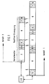
- einen Zeitplan für die in zwei selbständigen Gefäßen durchführbaren Verfahrensschritte,
- Fig. 2
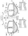
- einen Schnitt durch die beiden zusammenwirkenden Gefäße mit gemeinsamer Schwenk- und Hub-Einrichtung für die Elektroden und die Top-Blaslanze bzw. die Seitenlanzen und
- Fig. 3
- einen senkrechten Schnitt durch ein Gefäß als Elektrolichtbogen-Ofen mit einer Wandungs-Öffnung zum Abstechen der Schlacke.
- Dem gemäß Fig. 1 zu erläuternden Verfahren mit den Gefäßen 1 und 2, liegt gemäß Fig. 2 eine Schmelzanlage zugrunde, in der sich das Gefäß 1 und das Gefäß 2, als Elektrolichtbogenofen oder als Konverter ausgestaltet, in einem Abstand befinden, in dem eine Hub- und Schwenkeinrichtung 11 angeordnet ist, die über Arme 12 und 13 ein Elektroden-System 14 und eine Top-Blaslanze 15 in die Gefäße 1 und 2 absenken, hochfahren und schwenken kann. Dabei werden die Blaslanze 15 und das Elektroden-System 14 in den jeweiligen Betriebsabstand gebracht, wie gezeichnet. Das Gefäß 1 oder das Gefäß 2 kann jeweils auch als Erkerofen 16 mit einem außermittigen Abstich 17 oder als Schnauzenkipper und einem Ofendeckel 16a ausgeführt sein. In den Gefäßen 1, 2 oder 16 befindet sich die dem Verfahren zugrundeliegende Schmelze 18 mit einer Schlackenschicht 19. Die Gefäße 1 und 2 sind ferner mit Bodenspülsteinen 20 ausgestattet.
- Gemäß Fig. 1 ist nunmehr das Verfahren zum Erzeugen von nichtrostendem Stahl, insbesondere von chrom- oder chromnickelhaltigem Edelstahl, anhand von zwei parallelen, teilweise hintereinander ablaufenden Schmelzen ( Schmelze 1 und Schmelze 2) in dem Gefäß 1 und dem Gefäß 2 dargestellt. Die in Fig. 2 gezeigte Schmelz-einrichtung arbeitet momentan im Gefäß 1 mit dem Elektroden-System 14 und im Gefäß 2 mit der Top-Blaslanze 15 und / oder mit der Seitenlanze B.
- Die 1. Schmelze ( mit Vorschmelze bezeichnet) startet im Gefäß 2 mit dem Chargieren von Flüssig- und / oder Festeinsätzen im Schritt 1 , wobei phosphorreiches Roheisen eingesetzt wird. Danach wird in einem Schritt 2 das Entphosphoren des flüssigen Roheisens mit einer O2-Top-Blaslanze 15 bei kontinuierlicher Zugabe von Schlackenbildnern, wie z.B. Kalk, Dolomit, und ggfs. feste Kühlstoffe, wie z.B. Schrott, Eisenschwamm u. dgl. durchgeführt, wobei unter einem kontinuierlichen Ablaufenlassen der phosphorreichen Schlacke 19 durch eine seitliche Wandungs-Öffnung 21 a das Abschlacken erfolgt. In einem Schritt 3 wird ein End-Abschlacken durchgeführt, wobei die phosphorreiche Schlacke 19 sauber abgezogen wird. Damit hat bereits die Rostfrei-Erzeugung von Edelstahl begonnen. Dazu erfolgt im nächsten Schritt 4 das Chargieren von Schrott, Ferro-Legierungen und von Schlackebildnern. Im Schritt 5 beginnt das Einschmelzen und Erhitzen. Dazu ist das Elektroden-System 14 für die Dauer des Schrittes 5 über das Gefäß 1 zu schwenken und in Betriebsstellung wie gezeichnet einzufahren. Im nächsten Schritt 6 findet das O2 -Blasen mit der Top-Blaslanze 15 und der Seitenlanze B zum Entkohlen der chrom- und / oder chromnickelreichen Stahlschmelze statt. Falls erforderlich, werden feste Kühlstoffe kontinuierlich zugegeben, wie z.B. FeCr, FeNi, Schrott, Eisenschwamm u. dgl. und es wird bis zu einem Kohlenstoffgehalt kleiner 1,0% C geblasen. Im Schritt 7 erfolgt das Reduzieren der hochchromhaltigen Schlacke unter der Energie des Elektroden-Systems 14 bei Zugabe von Reduktionsmitteln, wie z.B. FeSi, Al, u. dgl. Im Schritt 8 wird der Flüssigstahl mit Schlacke abgestochen, wobei eine Restreduktion der Schlacke während des Abstichs und in der Pfanne durch starkes Spülen durch die Bodenspülsteine 20 vorgenommen wird.
- Das Chargieren von Roheisen kann auch über eine Rinne erfolgen. Sodann ist in Fig. 3 in der Gefäß-Wandung 21 eine verschließbare Wandungs-Öffnung 21 a für eine Seiten-Blaslanze B und / oder eine Top-Blaslanze 15 vorgesehen. Im Bereich des Gefäßes 1; 2 ist die Hub- und Schwenkeinrichtung 11 für ein schwenkbares Elektroden-System 14 und / oder die Top-Blaslanze 15 eingebracht, Die verschließbare Wandungs-Öffnung 21 a besitzt einen Hubantrieb 23 für eine Verschlussplatte 24. In der FF-Ausmauerung 26 ist an der Abstechkante ein Graphit-Balken 25 angeordnet, so dass bei leichten Kippbewegungen des Gefäßes 1; 2 auf der Kipplagerung 27 die Schlacke 19 abfließt. Das Abstechen des Flüssigstahls kann wie üblich durch den Bodenabstich 28 im Erker 30 erfolgen. Der Graphit-Balken 25 ist auf die geforderte Badspiegelhöhe 29 abgestimmt angeordnet. Die Wandungs-Öffnung 21 a befindet sich in der Wandung des Ofendeckels 16a.
- Zwischen den Gefäßen 1 und 2 (Fig. 1) ist eine Logistik 22 für das Einbringen von elektrischer Energie zum Einschmelzen und / oder Überhitzen der Schmelze 18 und / oder Reduzieren der Schlacke 19 in der Art vorgesehen, dass das Einschmelzen und / oder Überhitzen und / oder das Reduzieren in den beiden Gefäßen 1; 2 nicht zeitgleich durchgeführt und ebenso Sauerstoff über die Sauerstoff-Blaslanzen nur in bestimmten Zeitabschnitten zugeführt werden kann.
- Das Verfahren im Gefäß 1 beginnt daher mit dem Schritt 5 (Einschmelzen und Erhitzen), auf den der Schritt 6 (O2-Blasen mit Top-Blaslanze und Seitenlanzen zum Entkohlen) folgt, weiter mit dem Schritt 7 (Reduzieren der hochchromhaltigen Schlacke unter dem Lichtbogen und Zugabe von Reduktionsmitteln), sowie dem Schritt 8 (Abstechen des Flüssigstahls mit Schlacke) und tritt in ein neues Intervall mit dem Schritt 1 (Chargieren von phosphorreichem Flüssig-Roheisen) ein, an dessen Ende im Gefäß 2 das Elektroden-System 14 benötigt wird und in der dortigen Zeit im Gefäß 1 der Schritt 2 abläuft, in dem das Entphosphoren des Flüssig-Roheisens mit der O2-Blaslanze stattfindet. Dadurch wird eine gegenseitige Behinderung der Schmelzen in den beiden Gefäßen ausgeschlossen, was durch die Logistik 22 kontrolliert wird.
-
- 1.
- Gefäß 1
- 2.
- Gefäß 2
- 11.
- Hub- und Schwenkeinrichtung
- 12.
- Arm
- 13.
- Arm
- 14.
- Elektroden-System
- 15.
- Top-Blaslanze
- 16.
- Erkerofen
- 16a
- Ofendeckel
- 17.
- außermittiger Abstich
- 18.
- Schmelze
- 19.
- Schlacke / Schlackenschicht
- 20.
- Bodenspülstein
- 21.
- Gefäß-Wandung
- 21 a
- seitliche Wandungs-Öffnung
- 22.
- Logistik
- 23.
- Hubantrieb
- 24.
- Verschlussplatte
- 25.
- Graphit-Balken
- 26.
- FF-Ausmauerung
- 27.
- Kipplagerung
- 28.
- Bodenabstich
- 29.
- Badspiegelhöhe
- 30.
- Erker
- B
- Tür-Blaslanze, Seiten-Blaslanze
- Schritt 1
- Chargieren von phosphorreichem Flüssig-Roheisen
- Schritt 2
- Entphosphoren des Flüssig-Roheisens mit O2 -Top-Blaslanze
- Schritt 3
- End-Abschlacken
- Schritt 4
- Chargieren von Schrott, Ferro-Legierungen und Schlackenbildnern
- Schritt 5
- Einschmelzen und Erhitzen
- Schritt 6
- O2-Blasen mit Top-Blaslanze und Seitenlanzen zum Entkohlen
- Schritt 7
- Reduzieren der hochchromhaltigen Schlacke unter dem Lichtbogen und unter Zugabe von Reduktionsmitteln
- Schritt 8
- Abstechen des Flüssigstahls mit Schlacke
- O2
- ↓ Sauerstoff einführen
- O2
- ↑ Sauerstoff abschalten
Elektrolichtbogen einschalten
Elektrolichtbogen abschalten.
Claims (8)
- Verfahren zum Erzeugen von nichtrostendem Stahl, insbesondere von chrom- oder chromnickelhaltigem Edelstahl, unmittelbar aus phosphorreichem flüssigen Roheisen in einem einzigen Gefäß (1; 2), wobei nach einem Entphosphoren des Flüssig-Roheisens und nach Abziehen der phosphorreichen Schlacke (19) Legierungselemente in das Gefäß (1; 2) chargiert, danach eine Entkohlung der Schmelze (18) und eine Reduktion der Schlacke (19) durchgeführt und schließlich die Schmelze (18) mit der Schlacke (19) abgestochen wird, dadurch gekennzeichnet, dass durch mehrmaliges abwechselndes Einschwenken im Gefäß (1; 2) eine Top-Blaslanze (15) und ein Elektroden-System (14) eingesetzt werden, wobei im einzelnen folgende Verfahrensschritte hintereinander durchgeführt werden:• Entphosphoren des Roheisens bei gleichzeitigem Eisenverschlacken, Entkohlen und Entsilizieren unter Zugabe von Schlackenbildnern und/oder festen Kühlstoffen durch Sauerstoffaufblasen mit der Top-Blaslanze (15),• Einschmelzen und Erhitzen von zuchargiertem Chrom und/oder Schrott sowie anderen Legierungselementen und von Schlackenbildnern durch das Elektroden-System (14) nach Abführen der phosphorreichen Schlacke (19),• Entkohlen der chrom-und/oder chromnickelreichen Stahlschmelze (18) durch Sauerstoffaufblasen mit der Top-Blaslanze (15) und einer Seitenlanze (B) bis zu einem Kohlenstoffgehalt kleiner 1,0 %,• Reduzieren der hochchromhaltigen Schlacke (19) durch das Elektroden-System (14) unter Zugabe von Reduktionsmitteln.
- Verfahren nach Anspruch 1, dadurch gekennzeichnet, dass neben restlichen Einsatzstoffen 30 bis 80% flüssiges Roheisen eingesetzt wird.
- Verfahren nach Anspruch 1, 2 oder 3, dadurch gekennzeichnet, dass das flüssige, phosphorreiche Roheisen durch Sauerstoffaufblasen an zumindest zwei Badspiegelstellen entphosphort wird bei etwa gleichzeitigem kontinuierlichem Ablaufenlassen der flüssigen phosphorreichen Schlacke (19) durch eine seitliche Wandungs-Öffnung (21 a).
- Verfahren nach Anspruch 3, dadurch gekennzeichnet, dass zum End-Abschlacken die phosphorreiche Schlacke mit Restschlackengehalten kleiner 30% sauber abgezogen wird.
- Verfahren nach einem der Ansprüche 1 bis 4, dadurch gekennzeichnet, dass zum Entkohlen der chrom- und/oder nickelreichen Stahlschmelze, falls erforderlich, feste Kühlstoffe wie beispielsweise FeCr, FeNi, Schrott, Eisenschwamm u. dgl. kontinuierlich zugegeben werden.
- Verfahren nach einem der Ansprüche 1 bis 5, dadurch gekennzeichnet, dass die Schlacke (19) während des gemeinsamen Abstichs mit der Stahlschmelze (18) in die Pfanne (Perrin-Effekt) und/oder in der Pfanne durch starkes Spülen mittels Bodenspülsteinen (20) restlich final reduziert wird.
- Verfahren nach einem der Ansprüche 1 bis 6, dadurch gekennzeichnet, dass bei einem parallelen Einsatz von zwei Gefäßen (1; 2) zwischen den Gefäßen (1) und (2) eine Logistik (22) für das Einbringen von elektrischer Energie durch das Elektroden-System (14) und für das Einblasen von Sauerstoff über die Top-Blaslanze (15) und der Seitenlanze (B) derart gestaltet ist, dass das gleichzeitige Einbringen von elektrischer Energie bzw. das gleichzeitige Einblasen von Sauerstoff in den beiden Gefäßen (1) und (2) nicht zeitgleich durchführbar sind.
- Einrichtung zur Erzeugung von nichtrostendem, insbesondere chromhaltigem oder chromnickelhaltigem Stahl unmittelbar aus phosphorhaltigem flüssigen Roheisen in einer aus einem, zwei oder mehreren Gefäßen (1; 2) bestehenden Schmelzanlage, wobei mit Hilfe einer über jedes Gefäß (1; 2) einschwenkbaren Top-Blaslanze (15) und eines einschwenkbaren Elektroden-Systems (14) nach einem Entphosphoren des Flüssig-Roheisens und nach Abziehen der phosphorreichen Schlacke (19) Legierungselemente in das Gefäß (1; 2) chargiert, danach eine Entkohlung der Schmelze (18) und eine Reduktion der Schlacke (19) durchgeführt und schließlich die Schmelze (18) mit der Schlacke (19) abgestochen wird, insbesondere zur Durchführung des Verfahrens nach den Ansprüchen 1 bis 7, gekennzeichnet durch eine für eine Seiten-Blaslanze (B) und für die durch Kippen des Gefäßes (1; 2) abzustechende Schlacke (19) im Ofendeckel (16a) etwa auf der Badspiegelhöhe (29) angeordnete verschließbare Wandungs-Öffnung (21a) mit einem Hubantrieb (23) für eine Verschlussplatte (24) und mit einem an ihrer Abstechkante in der FF-Ausmauerung (26) angeordneten Graphit-Balken (25), so dass bei leichten Kippbewegungen des Gefäßes (1; 2) auf der Kipplagerung (27) die Schlacke (19) abfließt.
Applications Claiming Priority (3)
| Application Number | Priority Date | Filing Date | Title |
|---|---|---|---|
| DE2002115828 DE10215828B4 (de) | 2002-04-10 | 2002-04-10 | Verfahren und Einrichtung zum Erzeugen von nichtrostendem Stahl, insbesondere von chrom- oder chromnickelhaltigem Edelstahl |
| DE10215828 | 2002-04-10 | ||
| PCT/EP2003/002133 WO2003085140A1 (de) | 2002-04-10 | 2003-03-01 | Verfahren und einrichtung zum erzeugen von nichtrostendem stahl, insbesondere von chrom- oder chromnickelhaltigem edelstahl |
Publications (2)
| Publication Number | Publication Date |
|---|---|
| EP1492893A1 EP1492893A1 (de) | 2005-01-05 |
| EP1492893B1 true EP1492893B1 (de) | 2007-11-21 |
Family
ID=28684920
Family Applications (1)
| Application Number | Title | Priority Date | Filing Date |
|---|---|---|---|
| EP03714765A Expired - Lifetime EP1492893B1 (de) | 2002-04-10 | 2003-03-01 | Verfahren und einrichtung zum erzeugen von nichtrostendem stahl, insbesondere von chrom- oder chromnickelhaltigem edelstahl |
Country Status (10)
| Country | Link |
|---|---|
| EP (1) | EP1492893B1 (de) |
| JP (1) | JP2005526906A (de) |
| KR (1) | KR20040091715A (de) |
| CN (1) | CN1646707A (de) |
| AR (1) | AR039268A1 (de) |
| AU (1) | AU2003219006A1 (de) |
| DE (2) | DE10215828B4 (de) |
| RU (1) | RU2004133024A (de) |
| TW (1) | TW200306353A (de) |
| WO (1) | WO2003085140A1 (de) |
Cited By (1)
| Publication number | Priority date | Publication date | Assignee | Title |
|---|---|---|---|---|
| CN101705332B (zh) * | 2008-10-08 | 2011-04-13 | 张家港浦项不锈钢有限公司 | 使用高磷镍铬生铁制造不锈钢的工艺 |
Families Citing this family (8)
| Publication number | Priority date | Publication date | Assignee | Title |
|---|---|---|---|---|
| DE102004055206B4 (de) * | 2004-11-16 | 2012-08-30 | Sms Siemag Aktiengesellschaft | Verfahren zum Herstellen von Stahl mit hohem Mangan- und niedrigem Kohlenstoffgehalt |
| CN101020943A (zh) | 2006-07-12 | 2007-08-22 | 刘光火 | 氧化镍矿冶炼镍铬生铁工艺的降磷方法 |
| CN104294009B (zh) * | 2013-07-16 | 2016-03-30 | 上海宝锋工程技术有限公司 | 用于不锈钢脱硅冶炼的顶底复合吹炼方法 |
| DE102015110674A1 (de) * | 2015-07-02 | 2017-01-05 | Sms Group Gmbh | Umbausystem für einen Elektrolichtbogenofen (EAF) |
| CN111763793A (zh) * | 2020-05-27 | 2020-10-13 | 山西太钢不锈钢股份有限公司 | 用于制造高氧含量不锈钢的冶炼方法 |
| WO2022125792A1 (en) | 2020-12-10 | 2022-06-16 | Spm Oil & Gas Inc. | Mechanically resilient and wear resistant steel compositions and high-pressure pumps and pump components comprised thereof |
| EP4261290A4 (de) * | 2021-01-26 | 2024-05-15 | JFE Steel Corporation | Verfahren zum raffinieren von geschmolzenem eisen |
| KR102812519B1 (ko) | 2025-01-02 | 2025-05-26 | 천종열 | 자동화된 암모니아 열처리 설비를 이용한 특수강 제조 방법 |
Family Cites Families (4)
| Publication number | Priority date | Publication date | Assignee | Title |
|---|---|---|---|---|
| AT237000B (de) * | 1962-09-18 | 1964-11-25 | Guszstahlwerk Witten Ag | Verfahren zur Herstellung von legiertem Stahl |
| CA2166097C (en) * | 1993-06-30 | 2002-01-15 | Masataka Yano | Process for producing steel by converter |
| DE4445209C2 (de) * | 1994-12-17 | 1999-01-21 | Schloemann Siemag Ag | Verfahren und Vorrichtung zum Betreiben eines Doppelgefäß-Lichtbogenofens |
| DE19621143A1 (de) * | 1996-01-31 | 1997-08-07 | Mannesmann Ag | Verfahren zur Erzeugung nichtrostender Stähle |
-
2002
- 2002-04-10 DE DE2002115828 patent/DE10215828B4/de not_active Expired - Fee Related
-
2003
- 2003-02-27 TW TW92104125A patent/TW200306353A/zh unknown
- 2003-03-01 EP EP03714765A patent/EP1492893B1/de not_active Expired - Lifetime
- 2003-03-01 KR KR10-2004-7014227A patent/KR20040091715A/ko not_active Withdrawn
- 2003-03-01 WO PCT/EP2003/002133 patent/WO2003085140A1/de not_active Ceased
- 2003-03-01 AU AU2003219006A patent/AU2003219006A1/en not_active Abandoned
- 2003-03-01 RU RU2004133024/02A patent/RU2004133024A/ru not_active Application Discontinuation
- 2003-03-01 CN CNA038080540A patent/CN1646707A/zh active Pending
- 2003-03-01 DE DE50308647T patent/DE50308647D1/de not_active Expired - Lifetime
- 2003-03-01 JP JP2003582317A patent/JP2005526906A/ja not_active Withdrawn
- 2003-04-08 AR ARP030101232 patent/AR039268A1/es not_active Application Discontinuation
Cited By (1)
| Publication number | Priority date | Publication date | Assignee | Title |
|---|---|---|---|---|
| CN101705332B (zh) * | 2008-10-08 | 2011-04-13 | 张家港浦项不锈钢有限公司 | 使用高磷镍铬生铁制造不锈钢的工艺 |
Also Published As
| Publication number | Publication date |
|---|---|
| AU2003219006A1 (en) | 2003-10-20 |
| DE50308647D1 (de) | 2008-01-03 |
| WO2003085140A1 (de) | 2003-10-16 |
| DE10215828B4 (de) | 2007-08-02 |
| EP1492893A1 (de) | 2005-01-05 |
| JP2005526906A (ja) | 2005-09-08 |
| DE10215828A1 (de) | 2003-11-06 |
| KR20040091715A (ko) | 2004-10-28 |
| CN1646707A (zh) | 2005-07-27 |
| RU2004133024A (ru) | 2005-05-10 |
| TW200306353A (en) | 2003-11-16 |
| AR039268A1 (es) | 2005-02-16 |
Similar Documents
| Publication | Publication Date | Title |
|---|---|---|
| DE4445209C2 (de) | Verfahren und Vorrichtung zum Betreiben eines Doppelgefäß-Lichtbogenofens | |
| US6238453B1 (en) | Producing stainless steels in parallel operated vessels | |
| EP0820528B1 (de) | Anlage und verfahren zum herstellen von eisenschmelzen nach dem mehrzonenschmelzverfahren | |
| EP1492893B1 (de) | Verfahren und einrichtung zum erzeugen von nichtrostendem stahl, insbesondere von chrom- oder chromnickelhaltigem edelstahl | |
| EP2783548B1 (de) | Elektrolichtbogenofen und verfahren zu seinem betrieb | |
| DE19728102C2 (de) | Verfahren und Vorrichtung zur Herstellung von Stählen mit hohem Cr-Gehalt und/oder Ferrolegierungen | |
| WO2004104233A1 (de) | Verfahren zur rückgewinnung von metallischen elementen, insbesondere metallischem chrom, aus metalloxidhaltigen schlacken im elektrolichtbogenofen | |
| EP1332232B1 (de) | Verfahren zur erzeugung nichtrostender stähle, insbesondere chrom- und chromnickelhaltiger edelstähle | |
| DE1923596A1 (de) | Kontinuierliches Verfahren zur Stahlherstellung | |
| DE3426736C2 (de) | ||
| DE10209472B4 (de) | Verfahren zum Erzeugen von nichtrostendem Stahl, insbesondere von chrom- oder chromnickelhaltigem Edelstahl | |
| DE19526704C1 (de) | Einschmelzaggregat | |
| DE19545831C2 (de) | Verfahren zum Betreiben einer Doppelgefäß-Lichtbogenofen-Anlage sowie Doppelgefäß-Lichtbogenofen | |
| WO2001064962A1 (de) | Anlage zur herstellung von stahl | |
| DE19913645A1 (de) | Verfahren zum Regenerieren von Entschwefelungsschlacke | |
| DE4404313C2 (de) | Verfahren zum Aufschmelzen und Behandeln von Metallen und Anlage zur Durchführung des Verfahrens | |
| DE2033197A1 (de) | Verfahren und Vorrichtung von für die Weiterverarbeitung bestimmten Metallen bzw. Metallegierungen, insbesondere Stahl, oder Verbindungen dieser Metalle mit anderen Elementen, z. B. Metalloxyden, oder sonstigen schmelzbaren Erden oder Stoffen mit Hilfe des Elektro-Lichtbogenofens | |
| WO2005098053A2 (de) | Verfahren und anlage zum herstellen und erhöhen der jährlichen produktionsmenge von massenstahl oder hochwertigen stahlgüten in einer zwei-gefäss-anlage | |
| EP0140001A1 (de) | Verfahren zur Herstellung von Stählen mit hohem Reinheitsgrad und geringen Gasgehalten in Stahlwerken und Stahlgiessereien | |
| DE1935332C (de) | Frischverfahren für flüssiges, legiertes Roheisen, insbesondere vanadiunlhaltiges Roheisen | |
| DE10350959A1 (de) | Verfahren zur Rückgewinnung von metallischen Elementen aus metalloxidhaltigen Schlacken | |
| DE10137761A1 (de) | Verfahren zur Erzeugung nichtrostender Stähle, insbesondere chrom-und chromnickelhaltiger Edelstähle | |
| KR20190027552A (ko) | 크롬 또는 니켈을 함유한 스테인리스 특수강의 제조 방법 및 장치 | |
| DE102004046727A1 (de) | Verfahren und Einrichtung zum Herstellen von flüssigem Stahl | |
| DE9422137U1 (de) | Stahlwerkseinrichtung |
Legal Events
| Date | Code | Title | Description |
|---|---|---|---|
| PUAI | Public reference made under article 153(3) epc to a published international application that has entered the european phase |
Free format text: ORIGINAL CODE: 0009012 |
|
| 17P | Request for examination filed |
Effective date: 20040724 |
|
| AK | Designated contracting states |
Kind code of ref document: A1 Designated state(s): AT BE BG CH CY CZ DE DK EE ES FI FR GB GR HU IE IT LI LU MC NL PT RO SE SI SK TR |
|
| AX | Request for extension of the european patent |
Extension state: AL LT LV MK |
|
| 17Q | First examination report despatched |
Effective date: 20070201 |
|
| GRAP | Despatch of communication of intention to grant a patent |
Free format text: ORIGINAL CODE: EPIDOSNIGR1 |
|
| GRAS | Grant fee paid |
Free format text: ORIGINAL CODE: EPIDOSNIGR3 |
|
| GRAA | (expected) grant |
Free format text: ORIGINAL CODE: 0009210 |
|
| AK | Designated contracting states |
Kind code of ref document: B1 Designated state(s): AT BE BG CH CY CZ DE DK EE ES FI FR GB GR HU IE IT LI LU MC NL PT RO SE SI SK TR |
|
| REG | Reference to a national code |
Ref country code: GB Ref legal event code: FG4D Free format text: NOT ENGLISH |
|
| REG | Reference to a national code |
Ref country code: IE Ref legal event code: FG4D Free format text: LANGUAGE OF EP DOCUMENT: GERMAN |
|
| REG | Reference to a national code |
Ref country code: CH Ref legal event code: EP |
|
| REF | Corresponds to: |
Ref document number: 50308647 Country of ref document: DE Date of ref document: 20080103 Kind code of ref document: P |
|
| GBT | Gb: translation of ep patent filed (gb section 77(6)(a)/1977) |
Effective date: 20080228 |
|
| PG25 | Lapsed in a contracting state [announced via postgrant information from national office to epo] |
Ref country code: NL Free format text: LAPSE BECAUSE OF FAILURE TO SUBMIT A TRANSLATION OF THE DESCRIPTION OR TO PAY THE FEE WITHIN THE PRESCRIBED TIME-LIMIT Effective date: 20071121 Ref country code: ES Free format text: LAPSE BECAUSE OF FAILURE TO SUBMIT A TRANSLATION OF THE DESCRIPTION OR TO PAY THE FEE WITHIN THE PRESCRIBED TIME-LIMIT Effective date: 20080304 Ref country code: SE Free format text: LAPSE BECAUSE OF FAILURE TO SUBMIT A TRANSLATION OF THE DESCRIPTION OR TO PAY THE FEE WITHIN THE PRESCRIBED TIME-LIMIT Effective date: 20080221 |
|
| NLV1 | Nl: lapsed or annulled due to failure to fulfill the requirements of art. 29p and 29m of the patents act | ||
| PG25 | Lapsed in a contracting state [announced via postgrant information from national office to epo] |
Ref country code: BG Free format text: LAPSE BECAUSE OF FAILURE TO SUBMIT A TRANSLATION OF THE DESCRIPTION OR TO PAY THE FEE WITHIN THE PRESCRIBED TIME-LIMIT Effective date: 20080221 Ref country code: FI Free format text: LAPSE BECAUSE OF FAILURE TO SUBMIT A TRANSLATION OF THE DESCRIPTION OR TO PAY THE FEE WITHIN THE PRESCRIBED TIME-LIMIT Effective date: 20071121 Ref country code: SI Free format text: LAPSE BECAUSE OF FAILURE TO SUBMIT A TRANSLATION OF THE DESCRIPTION OR TO PAY THE FEE WITHIN THE PRESCRIBED TIME-LIMIT Effective date: 20071121 |
|
| PG25 | Lapsed in a contracting state [announced via postgrant information from national office to epo] |
Ref country code: DK Free format text: LAPSE BECAUSE OF FAILURE TO SUBMIT A TRANSLATION OF THE DESCRIPTION OR TO PAY THE FEE WITHIN THE PRESCRIBED TIME-LIMIT Effective date: 20071121 Ref country code: CZ Free format text: LAPSE BECAUSE OF FAILURE TO SUBMIT A TRANSLATION OF THE DESCRIPTION OR TO PAY THE FEE WITHIN THE PRESCRIBED TIME-LIMIT Effective date: 20071121 |
|
| PG25 | Lapsed in a contracting state [announced via postgrant information from national office to epo] |
Ref country code: SK Free format text: LAPSE BECAUSE OF FAILURE TO SUBMIT A TRANSLATION OF THE DESCRIPTION OR TO PAY THE FEE WITHIN THE PRESCRIBED TIME-LIMIT Effective date: 20071121 Ref country code: RO Free format text: LAPSE BECAUSE OF FAILURE TO SUBMIT A TRANSLATION OF THE DESCRIPTION OR TO PAY THE FEE WITHIN THE PRESCRIBED TIME-LIMIT Effective date: 20071121 |
|
| PLBE | No opposition filed within time limit |
Free format text: ORIGINAL CODE: 0009261 |
|
| STAA | Information on the status of an ep patent application or granted ep patent |
Free format text: STATUS: NO OPPOSITION FILED WITHIN TIME LIMIT |
|
| BERE | Be: lapsed |
Owner name: SMS DEMAG A.G. Effective date: 20080331 |
|
| PG25 | Lapsed in a contracting state [announced via postgrant information from national office to epo] |
Ref country code: PT Free format text: LAPSE BECAUSE OF FAILURE TO SUBMIT A TRANSLATION OF THE DESCRIPTION OR TO PAY THE FEE WITHIN THE PRESCRIBED TIME-LIMIT Effective date: 20080421 |
|
| REG | Reference to a national code |
Ref country code: IE Ref legal event code: FD4D |
|
| 26N | No opposition filed |
Effective date: 20080822 |
|
| PG25 | Lapsed in a contracting state [announced via postgrant information from national office to epo] |
Ref country code: MC Free format text: LAPSE BECAUSE OF NON-PAYMENT OF DUE FEES Effective date: 20080331 Ref country code: FR Free format text: LAPSE BECAUSE OF FAILURE TO SUBMIT A TRANSLATION OF THE DESCRIPTION OR TO PAY THE FEE WITHIN THE PRESCRIBED TIME-LIMIT Effective date: 20080905 Ref country code: IE Free format text: LAPSE BECAUSE OF FAILURE TO SUBMIT A TRANSLATION OF THE DESCRIPTION OR TO PAY THE FEE WITHIN THE PRESCRIBED TIME-LIMIT Effective date: 20071121 |
|
| REG | Reference to a national code |
Ref country code: CH Ref legal event code: PL |
|
| PG25 | Lapsed in a contracting state [announced via postgrant information from national office to epo] |
Ref country code: LI Free format text: LAPSE BECAUSE OF NON-PAYMENT OF DUE FEES Effective date: 20080331 Ref country code: EE Free format text: LAPSE BECAUSE OF FAILURE TO SUBMIT A TRANSLATION OF THE DESCRIPTION OR TO PAY THE FEE WITHIN THE PRESCRIBED TIME-LIMIT Effective date: 20071121 Ref country code: GR Free format text: LAPSE BECAUSE OF FAILURE TO SUBMIT A TRANSLATION OF THE DESCRIPTION OR TO PAY THE FEE WITHIN THE PRESCRIBED TIME-LIMIT Effective date: 20080222 Ref country code: CH Free format text: LAPSE BECAUSE OF NON-PAYMENT OF DUE FEES Effective date: 20080331 |
|
| PG25 | Lapsed in a contracting state [announced via postgrant information from national office to epo] |
Ref country code: BE Free format text: LAPSE BECAUSE OF NON-PAYMENT OF DUE FEES Effective date: 20080331 |
|
| PG25 | Lapsed in a contracting state [announced via postgrant information from national office to epo] |
Ref country code: CY Free format text: LAPSE BECAUSE OF FAILURE TO SUBMIT A TRANSLATION OF THE DESCRIPTION OR TO PAY THE FEE WITHIN THE PRESCRIBED TIME-LIMIT Effective date: 20071121 |
|
| PG25 | Lapsed in a contracting state [announced via postgrant information from national office to epo] |
Ref country code: HU Free format text: LAPSE BECAUSE OF FAILURE TO SUBMIT A TRANSLATION OF THE DESCRIPTION OR TO PAY THE FEE WITHIN THE PRESCRIBED TIME-LIMIT Effective date: 20080522 Ref country code: LU Free format text: LAPSE BECAUSE OF NON-PAYMENT OF DUE FEES Effective date: 20080301 |
|
| PG25 | Lapsed in a contracting state [announced via postgrant information from national office to epo] |
Ref country code: TR Free format text: LAPSE BECAUSE OF FAILURE TO SUBMIT A TRANSLATION OF THE DESCRIPTION OR TO PAY THE FEE WITHIN THE PRESCRIBED TIME-LIMIT Effective date: 20071121 |
|
| REG | Reference to a national code |
Ref country code: DE Ref legal event code: R082 Ref document number: 50308647 Country of ref document: DE Representative=s name: HEMMERICH & KOLLEGEN, DE Ref country code: DE Ref legal event code: R081 Ref document number: 50308647 Country of ref document: DE Owner name: SMS GROUP GMBH, DE Free format text: FORMER OWNER: SMS SIEMAG AKTIENGESELLSCHAFT, 40237 DUESSELDORF, DE |
|
| PGFP | Annual fee paid to national office [announced via postgrant information from national office to epo] |
Ref country code: GB Payment date: 20180321 Year of fee payment: 16 Ref country code: DE Payment date: 20180322 Year of fee payment: 16 |
|
| PGFP | Annual fee paid to national office [announced via postgrant information from national office to epo] |
Ref country code: AT Payment date: 20180322 Year of fee payment: 16 |
|
| PGFP | Annual fee paid to national office [announced via postgrant information from national office to epo] |
Ref country code: IT Payment date: 20180327 Year of fee payment: 16 |
|
| REG | Reference to a national code |
Ref country code: DE Ref legal event code: R119 Ref document number: 50308647 Country of ref document: DE |
|
| REG | Reference to a national code |
Ref country code: AT Ref legal event code: MM01 Ref document number: 379122 Country of ref document: AT Kind code of ref document: T Effective date: 20190301 |
|
| GBPC | Gb: european patent ceased through non-payment of renewal fee |
Effective date: 20190301 |
|
| PG25 | Lapsed in a contracting state [announced via postgrant information from national office to epo] |
Ref country code: DE Free format text: LAPSE BECAUSE OF NON-PAYMENT OF DUE FEES Effective date: 20191001 Ref country code: AT Free format text: LAPSE BECAUSE OF NON-PAYMENT OF DUE FEES Effective date: 20190301 Ref country code: GB Free format text: LAPSE BECAUSE OF NON-PAYMENT OF DUE FEES Effective date: 20190301 |
|
| PG25 | Lapsed in a contracting state [announced via postgrant information from national office to epo] |
Ref country code: IT Free format text: LAPSE BECAUSE OF NON-PAYMENT OF DUE FEES Effective date: 20190301 |