EP1492930B1 - Elektromechanisches zylinderschloss und schlüsselkombination mit optischem kode - Google Patents
Elektromechanisches zylinderschloss und schlüsselkombination mit optischem kode Download PDFInfo
- Publication number
- EP1492930B1 EP1492930B1 EP03722391A EP03722391A EP1492930B1 EP 1492930 B1 EP1492930 B1 EP 1492930B1 EP 03722391 A EP03722391 A EP 03722391A EP 03722391 A EP03722391 A EP 03722391A EP 1492930 B1 EP1492930 B1 EP 1492930B1
- Authority
- EP
- European Patent Office
- Prior art keywords
- key
- optical code
- combination according
- lock
- pin
- Prior art date
- Legal status (The legal status is an assumption and is not a legal conclusion. Google has not performed a legal analysis and makes no representation as to the accuracy of the status listed.)
- Expired - Lifetime
Links
- 230000003287 optical effect Effects 0.000 title claims abstract description 40
- 230000000903 blocking effect Effects 0.000 claims abstract description 26
- 238000003780 insertion Methods 0.000 claims abstract description 8
- 230000037431 insertion Effects 0.000 claims abstract description 8
- 238000001514 detection method Methods 0.000 claims description 3
- 230000007246 mechanism Effects 0.000 abstract description 5
- 239000011162 core material Substances 0.000 description 16
- 239000003990 capacitor Substances 0.000 description 3
- 230000005693 optoelectronics Effects 0.000 description 3
- 230000008901 benefit Effects 0.000 description 2
- 230000000284 resting effect Effects 0.000 description 2
- 239000000919 ceramic Substances 0.000 description 1
- 230000001934 delay Effects 0.000 description 1
- 230000001419 dependent effect Effects 0.000 description 1
- 230000005611 electricity Effects 0.000 description 1
- 230000007613 environmental effect Effects 0.000 description 1
- 238000009434 installation Methods 0.000 description 1
- 230000003993 interaction Effects 0.000 description 1
- 239000000463 material Substances 0.000 description 1
- 238000000034 method Methods 0.000 description 1
- 230000008569 process Effects 0.000 description 1
- 239000000126 substance Substances 0.000 description 1
Images


Classifications
-
- E—FIXED CONSTRUCTIONS
- E05—LOCKS; KEYS; WINDOW OR DOOR FITTINGS; SAFES
- E05B—LOCKS; ACCESSORIES THEREFOR; HANDCUFFS
- E05B47/00—Operating or controlling locks or other fastening devices by electric or magnetic means
- E05B47/06—Controlling mechanically-operated bolts by electro-magnetically-operated detents
- E05B47/0611—Cylinder locks with electromagnetic control
- E05B47/0619—Cylinder locks with electromagnetic control by blocking the rotor
- E05B47/0626—Cylinder locks with electromagnetic control by blocking the rotor radially
-
- E—FIXED CONSTRUCTIONS
- E05—LOCKS; KEYS; WINDOW OR DOOR FITTINGS; SAFES
- E05B—LOCKS; ACCESSORIES THEREFOR; HANDCUFFS
- E05B47/00—Operating or controlling locks or other fastening devices by electric or magnetic means
- E05B47/0001—Operating or controlling locks or other fastening devices by electric or magnetic means with electric actuators; Constructional features thereof
- E05B47/0011—Operating or controlling locks or other fastening devices by electric or magnetic means with electric actuators; Constructional features thereof with piezoelectric actuators
-
- E—FIXED CONSTRUCTIONS
- E05—LOCKS; KEYS; WINDOW OR DOOR FITTINGS; SAFES
- E05B—LOCKS; ACCESSORIES THEREFOR; HANDCUFFS
- E05B49/00—Electric permutation locks; Circuits therefor ; Mechanical aspects of electronic locks; Mechanical keys therefor
- E05B49/002—Keys with mechanical characteristics, e.g. notches, perforations, opaque marks
- E05B49/006—Keys with mechanical characteristics, e.g. notches, perforations, opaque marks actuating opto-electronic devices
-
- Y—GENERAL TAGGING OF NEW TECHNOLOGICAL DEVELOPMENTS; GENERAL TAGGING OF CROSS-SECTIONAL TECHNOLOGIES SPANNING OVER SEVERAL SECTIONS OF THE IPC; TECHNICAL SUBJECTS COVERED BY FORMER USPC CROSS-REFERENCE ART COLLECTIONS [XRACs] AND DIGESTS
- Y10—TECHNICAL SUBJECTS COVERED BY FORMER USPC
- Y10T—TECHNICAL SUBJECTS COVERED BY FORMER US CLASSIFICATION
- Y10T70/00—Locks
- Y10T70/70—Operating mechanism
- Y10T70/7051—Using a powered device [e.g., motor]
- Y10T70/7062—Electrical type [e.g., solenoid]
- Y10T70/7068—Actuated after correct combination recognized [e.g., numerical, alphabetical, or magnet[s] pattern]
- Y10T70/7073—Including use of a key
- Y10T70/7079—Key rotated [e.g., Eurocylinder]
-
- Y—GENERAL TAGGING OF NEW TECHNOLOGICAL DEVELOPMENTS; GENERAL TAGGING OF CROSS-SECTIONAL TECHNOLOGIES SPANNING OVER SEVERAL SECTIONS OF THE IPC; TECHNICAL SUBJECTS COVERED BY FORMER USPC CROSS-REFERENCE ART COLLECTIONS [XRACs] AND DIGESTS
- Y10—TECHNICAL SUBJECTS COVERED BY FORMER USPC
- Y10T—TECHNICAL SUBJECTS COVERED BY FORMER US CLASSIFICATION
- Y10T70/00—Locks
- Y10T70/70—Operating mechanism
- Y10T70/7051—Using a powered device [e.g., motor]
- Y10T70/7062—Electrical type [e.g., solenoid]
- Y10T70/7102—And details of blocking system [e.g., linkage, latch, pawl, spring]
-
- Y—GENERAL TAGGING OF NEW TECHNOLOGICAL DEVELOPMENTS; GENERAL TAGGING OF CROSS-SECTIONAL TECHNOLOGIES SPANNING OVER SEVERAL SECTIONS OF THE IPC; TECHNICAL SUBJECTS COVERED BY FORMER USPC CROSS-REFERENCE ART COLLECTIONS [XRACs] AND DIGESTS
- Y10—TECHNICAL SUBJECTS COVERED BY FORMER USPC
- Y10T—TECHNICAL SUBJECTS COVERED BY FORMER US CLASSIFICATION
- Y10T70/00—Locks
- Y10T70/70—Operating mechanism
- Y10T70/7441—Key
- Y10T70/7486—Single key
- Y10T70/7508—Tumbler type
- Y10T70/7559—Cylinder type
- Y10T70/7588—Rotary plug
- Y10T70/7593—Sliding tumblers
- Y10T70/7599—Transverse of plug
- Y10T70/7605—Pin tumblers
-
- Y—GENERAL TAGGING OF NEW TECHNOLOGICAL DEVELOPMENTS; GENERAL TAGGING OF CROSS-SECTIONAL TECHNOLOGIES SPANNING OVER SEVERAL SECTIONS OF THE IPC; TECHNICAL SUBJECTS COVERED BY FORMER USPC CROSS-REFERENCE ART COLLECTIONS [XRACs] AND DIGESTS
- Y10—TECHNICAL SUBJECTS COVERED BY FORMER USPC
- Y10T—TECHNICAL SUBJECTS COVERED BY FORMER US CLASSIFICATION
- Y10T70/00—Locks
- Y10T70/70—Operating mechanism
- Y10T70/7441—Key
- Y10T70/7486—Single key
- Y10T70/7508—Tumbler type
- Y10T70/7559—Cylinder type
- Y10T70/7588—Rotary plug
- Y10T70/7593—Sliding tumblers
- Y10T70/7599—Transverse of plug
- Y10T70/7616—Including sidebar
-
- Y—GENERAL TAGGING OF NEW TECHNOLOGICAL DEVELOPMENTS; GENERAL TAGGING OF CROSS-SECTIONAL TECHNOLOGIES SPANNING OVER SEVERAL SECTIONS OF THE IPC; TECHNICAL SUBJECTS COVERED BY FORMER USPC CROSS-REFERENCE ART COLLECTIONS [XRACs] AND DIGESTS
- Y10—TECHNICAL SUBJECTS COVERED BY FORMER USPC
- Y10T—TECHNICAL SUBJECTS COVERED BY FORMER US CLASSIFICATION
- Y10T70/00—Locks
- Y10T70/70—Operating mechanism
- Y10T70/7441—Key
- Y10T70/7768—Key-removal preventing
-
- Y—GENERAL TAGGING OF NEW TECHNOLOGICAL DEVELOPMENTS; GENERAL TAGGING OF CROSS-SECTIONAL TECHNOLOGIES SPANNING OVER SEVERAL SECTIONS OF THE IPC; TECHNICAL SUBJECTS COVERED BY FORMER USPC CROSS-REFERENCE ART COLLECTIONS [XRACs] AND DIGESTS
- Y10—TECHNICAL SUBJECTS COVERED BY FORMER USPC
- Y10T—TECHNICAL SUBJECTS COVERED BY FORMER US CLASSIFICATION
- Y10T70/00—Locks
- Y10T70/70—Operating mechanism
- Y10T70/7441—Key
- Y10T70/7915—Tampering prevention or attack defeating
- Y10T70/7955—Keyhole guards
- Y10T70/7977—Key-controlled
Definitions
- the present invention relates generally to electro-mechanical key and lock devices and more particularly to an electro-mechanical cylinder lock-key combination using an optical code, such as a holographic code or a bar code provided on the key.
- an optical code such as a holographic code or a bar code provided on the key.
- An object of the present invention is to provide a key and lock device of the kind initially mentioned, wherein a high degree of security is obtained while the space requirements are kept to a minimum.
- the invention is based on the realisation that the movement of at least one of the blocking elements conventionally found in a mechanical lock can be prevented by the provision of an optical code element on the key.
- the optical code element is provided in the form of a hologram. This provides for a very high level of security thanks to the huge amount of possible codes and the difficulty in copying the key.
- a reflective bar code is provided as optical code on the key.
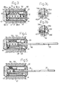
- FIG. 1 an overall perspective view of an electro mechanical cylinder lock-key combination 1 according to the invention is shown.
- the combination comprises a generally cylindrical cylinder housing 10 and a key 20 inserted into a key-way of a cylinder core 30 rotatably provided in the cylinder housing.
- a campiece 12 is actuated so as to act on a follower of a lock device.
- the cylinder housing 10 has the same general shape as conventional cylinder housings and the lock cylinder according to the invention can thus replace already installed all-mechanical lock cylinders.
- the key 20 is shown in its entirety in fig. 2. It has a conventional shape and comprises a grip portion 22 and a bit portion 24.
- the bit portion has an upper code surface 26 arranged to cooperate with tumbler pins provided in the lock cylinder.
- an elongated holographic image or hologram 28 having a surface being essentially flush with the side surface of the bit portion so as not to interfere with the insertion of the key into the cylinder core 30.
- the hologram functions as an additional code and a key must thus have both a correct mechanical code, i.e., code surface 26, and optical code, i.e., hologram 28. This adds a further level of security as compared to an all-mechanical lock.
- FIG. 3 A top sectional view of the lock cylinder is shown in fig. 3, wherein it is seen how the elongated cylinder core 30 is provided in the cylinder housing 10.
- a key-way 32 is provided centrally in the cylinder core so as to receive the key 20.
- Centrally aligned in the cylinder core are also six pin tumbler chambers 34-39, wherein the five front chambers 34-38 each contains conventional pin tumblers acting as blocking elements when a key having incorrect mechanical code is inserted in the cylinder.
- An example of pin tumbler is given in fig. 3a, showing a top pin 34a and a bottom pin 34b.
- the inner pin tumbler chamber 39 contains a conventional top pin 39a and a special kind of bottom pin, designated 39b in fig. 3b.
- This pin is provided with a circumferential waist or indent 39b' arranged to receive an outer portion of a pin-blocking element 40 provided at the outer end of a piezo-electric bender 42.
- This bender is arranged to move the pin blocking element 40 into and out of engagement with the waist portion 39b' of the special pin 39b. This function will be further explained below.
- the inner end of the piezo-electric bender 42 is fixed so as to make the outer end move when current flows through the piezo-electric bender.
- the inner pin tumbler as electronically controlled blocking element, several advantages are obtained. Firstly, the time from when the key 20 enters the cylinder core 30 to when it contacts the inner pin tumbler is long enough for the electronics to process the information in the optical code and control the pin tumbler 39a, 39b accordingly. Secondly, the piezo-electric bender 42 can be made long enough so as to displace the pin-blocking element 40 out of engagement with the special pin tumbler.
- ASIC application specific integrated circuit
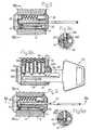
- a striking pin or "hammer” 50 running in a cylindrical cavity 52 in the cylinder core 30.
- the hammer is provided with a finger 54 arranged to cooperate with the tip of the key 20 during insertion thereof and is spring-biased towards the front end of the cylinder core 30 by means of a helical spring 56.
- An electric capacitor 58 is connected to the electrical power consuming components of the lock cylinder and is provided for storing electric energy by these components.
- a piezo-electric generator 60 in the cavity 52.
- the generator comprises piezo-electric ceramic, i.e., a material made of crystalline substance, which creates charges of electricity by the application of pressure and vice versa.
- the generator functions in the following way. In its resting position shown in fig. 3, the hammer 50 is pressed against the generator 60 by means of the force exerted by the helical spring 56. When the hammer is moved from this position by the key tip, se fig. 4, this force is removed and the generator 60 thus produces a weak electric current, which is supplied to the ASIC 44 and the laser diode 46.
- the current thus functions as a "wake up signal" for the ASIC, which is essentially powered by the capacitor 58.
- the hammer is returned to its original position, as will be described below with reference to fig. 7, mechanical energy is again converted into electric energy, charging the capacitor 58.
- the helical spring 56 can be given a characteristics adapted to provide defined force on the hammer.
- fig. 4 there is shown how the key is inserted into the key-way.
- the hammer 50 is moved from its resting position shown in fig. 3 when the tip of the key bit reaches the finger 54 thereof.
- the electric energy thus created by the generator 60 is directed to the ASIC 44, thereby making it operative.
- the laser diode 46 is then controlled by the ASIC to emit a laser beam in the direction of the side of the key bit provided with the hologram containing the holographic code.
- the hologram breaks up this laser beam in between 1 and 32 sub-beams and these are reflected onto the opto-electronic sensors 48 in dependence of the holographic code.
- the 32 bit optical code contained in the hologram is recorded by the sensors 48 and this code is transmitted to the ASIC 44.
- the correct optical code of the cylinder is stored in the ASIC. This correct code is compared with the code recorded by the sensors 48 and if they are identical, then the laser diode 46 is switched off and the pin-blocking element 40 is moved to a non-blocking position, as will be explained below. If the codes differ from each other, the laser diode is still switched off but the pin-blocking element 40 is left in blocking position.
- the ASIC connects the generator 60 and the piezo-electric bender 40.
- the generator When the hammer is released and hits the piezo-electric generator, the generator generates a voltage, which is directed across the piezo-electric bender 42.
- the generator 60 and the bender 42 thereby form a matched electrical circuit, providing a reliable actuator.
- the voltage across the piezo-electric bender makes it bend and thereby moves the pin blocking element 40 out of engagement with the special blocking pin 39b. With the pin blocking element in this position, the pins 39a, 39b function as the ordinary pins 34a,b - 38a,b.
- the tip of the key 20 pushes the pins 39a,b upward, see fig.
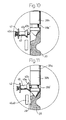
- the pin blocking element remains in engagement with the special pin 39b and the special pin tumbler 39a,b is stuck in position, see fig. 11. This in turn prevents the key 20 from being fully inserted into the cylinder core and it can only be inserted to the position shown in fig. 9 and 9b.
- the pin-blocking element 40 is shown in detail in fig. 11 in the position wherein a user of a key having incorrect optical code tries to push the key to its fully inserted position.
- the pin-blocking element is attached to the piezo-electric bender 42 through an aperture therethrough and is provided with a tapering flange 40a in the direction of the pin 39b. Its outer portion ends in a tip 40b dimensioned so as to fit into the waist potion 39b' of the special pin 39b.
- the pin-blocking element 40 is normally kept level by means of the spring force provided by a helical spring 40c.
- the optical code could be provided not on the side surface of the key bit but on the underside thereof.
- the inventive lock cylinder is provided with a special blocking pin tumbler arranged to be released by a piezo-electric bender upon detection of a correct optical code.
- the piezo-electric bender could of course be replaced by another kind of actuator, such as a solenoid etc.
- the battery found in many electro-magnetic locks is dispensed with.
- the inventive idea is also applicable to a lock having an internal battery or being externally powered.
- the inner pin tumbler is used as the electronically blocked element.
- other pin tumblers can be blocked either in addition to or instead of the inner pin tumbler.
- the electronic lock mechanism has been shown controlled by means of an ASIC. Any micro controller or other processing unit can of course be used for that purpose.
Landscapes
- Physics & Mathematics (AREA)
- Electromagnetism (AREA)
- Lock And Its Accessories (AREA)
Claims (14)
- Elektromechanische Zylinderschloss/Schlüssel-Kombination, aufweisend ein Gehäuse (10), welches eine Bohrung aufweist;
einen Kern (30), der drehbar in der Bohrung angeordnet ist und welcher einen Schlüsselweg (32) zum Aufnehmen eines Schlüssels (20) aufweist, welcher einen Griffabschnitt (22) und einen Schlüsselbartabschnitt (24) aufweist;
eine Mehrzahl von schlüsselbetätigten beweglichen Blockierelementen (34a, b - 39a, b) zum Blockieren der Drehung des Kerns relativ zu dem Gehäuse, wenn nicht ein richtiger Schlüssel in den Schlüsselweg eingeführt ist;
eine elektronische Verarbeitungseinheit (44);
ein optisches Code-Element (28; 28'), das auf dem Schlüsselbartabschnitt des Schlüssels vorgesehen ist;
einen optischen Code-Leser (46, 48), der in dem Schloss vorgesehen ist;
gekennzeichnet durch
ein Bolzenelement (39b), welches zumindest eines von den schlüsselbetätigten beweglichen Blockierelementen umfasst, wobei das Bolzenelement die vollständige Einführung des Schlüssels (20) in den Schlüsselweg (32) blockiert, wenn die Bewegung des Bolzenelements verhindert wird,
ein elektronisch gesteuertes Riegelelement (40), das zwischen einer Verriegelungsposition, in welcher die Bewegung des Bolzenelements (39b) durch das verriegelnde Element verhindert wird, und einer Freigabeposition bewegbar ist, in welcher die Bewegung des Bolzenelements durch das verriegelnde Element erlaubt wird, und
Mittel (42) zum Bewegen des Riegelelements zu der Freigabeposition bei Erfassung von einem richtigen optischen Code-Element (28, 28') auf dem Schlüssel durch den optischen Code-Leser (46, 48). - Kombination nach Anspruch 1, wobei das optische Code-Element ein holographisches Bild (28) ist.
- Kombination nach Anspruch 2, wobei das holographische Bild (28) mit einer Oberfläche versehen ist, die im Wesentlichen bündig mit einer Oberfläche des Schlüsselbartabschnitts (24) des Schlüssels (20) ist.
- Kombination nach Anspruch 2 oder 3, wobei der optische Code-Leser eine Laserdiode (46) und einen optischen Sensor (48) umfasst.
- Kombination nach Anspruch 1, wobei das optische Code-Element einen Barcode (28') umfasst.
- Kombination nach Anspruch 5, wobei der optische Code-Leser eine lichtaussendende Diode (46) und einen optischen Sensor (48) umfasst.
- Kombination nach irgendeinem der Ansprüche 2-6, wobei das Bolzenelement ein Stift (39b) ist, welcher eine Kerbe (39b') aufweist zum Aufnehmen eines Abschnitts (40b) des Riegelelements (40).
- Kombination nach Anspruch 7, wobei das Riegelelement (40) auf einem biegbaren Element (42) vorgesehen ist.
- Kombination nach Anspruch 8, wobei das biegbare Element (42) ein piezoelektrisches Biegeelement ist.
- Kombination nach irgendeinem der Ansprüche 2-9, wobei das Riegelelement (40) mit einem verjüngten Flansch (40a) versehen ist, der angeordnet ist, um das Riegelelement in Richtung zu dem Bolzenelement (39b) zu zwingen beim Einführen eines Schlüssels (20), welcher ein inkorrektes optisches Code-Element (28; 28') aufweist.
- Kombination nach irgendeinem der Ansprüche 2-10, wobei das Bolzenelement Teil eines inneren Stiftzuhalters (39b) ist.
- Kombination nach irgendeinem der Ansprüche 1-11, aufweisend einen piezoelektrischen Generator (60), der angeordnet ist, um eine mechanische Leistung, welche durch Einführen des Schlüssels (20) in den Kern (30) erzeugt wird, in elektrische Leistung umzuwandeln.
- Kombination nach Anspruch 12, aufweisend einen federbelasteten (56) Schlagstift (50), der mittels des Schlüssels (20) bewegbar ist zu und von einer Position, in welcher er eine Kraft auf den piezoelektrischen Generator (60) ausübt.
- Kombination nach Anspruch 12 oder 13, aufweisend Mittel zum Zuführen von elektrischem Strom, welcher durch den piezoelektrischen Generator (60) erzeugt wird, zu dem biegbaren Element (42), um das elektronisch gesteuerte Element (40) in seine Freigabeposition zu bewegen bei Erfassung eines korrekten optischen Code-Elements (28, 28').
Applications Claiming Priority (3)
| Application Number | Priority Date | Filing Date | Title |
|---|---|---|---|
| DK200200538A DK174939B1 (da) | 2002-04-11 | 2002-04-11 | Elektro-mekanisk cylinder-lås-nøgle kombination med optisk kode og nøgle dertil |
| DK200200538 | 2002-04-11 | ||
| PCT/EP2003/003464 WO2003085227A1 (en) | 2002-04-11 | 2003-04-02 | Electro-mechanical cylinder lock-key combination with optical code |
Publications (2)
| Publication Number | Publication Date |
|---|---|
| EP1492930A1 EP1492930A1 (de) | 2005-01-05 |
| EP1492930B1 true EP1492930B1 (de) | 2006-11-22 |
Family
ID=28685788
Family Applications (1)
| Application Number | Title | Priority Date | Filing Date |
|---|---|---|---|
| EP03722391A Expired - Lifetime EP1492930B1 (de) | 2002-04-11 | 2003-04-02 | Elektromechanisches zylinderschloss und schlüsselkombination mit optischem kode |
Country Status (9)
| Country | Link |
|---|---|
| US (1) | US7140214B2 (de) |
| EP (1) | EP1492930B1 (de) |
| AT (1) | ATE346208T1 (de) |
| AU (1) | AU2003229600A1 (de) |
| CA (1) | CA2482662A1 (de) |
| DE (1) | DE60309851D1 (de) |
| DK (1) | DK174939B1 (de) |
| NO (1) | NO20044890L (de) |
| WO (1) | WO2003085227A1 (de) |
Families Citing this family (31)
| Publication number | Priority date | Publication date | Assignee | Title |
|---|---|---|---|---|
| EP2489815A3 (de) * | 2005-04-11 | 2012-11-14 | Keso Ag | Schliessvorrichtung |
| BRPI0504546A (pt) * | 2005-10-03 | 2007-06-12 | Papaiz Ind E Com Ltda | pino de auto-bloqueio |
| CH699726B1 (de) * | 2006-11-16 | 2010-04-30 | Kaba Ag | Schliessvorrichtung. |
| US8056379B2 (en) * | 2007-01-04 | 2011-11-15 | Schlage Lock Company | Lock cylinder with offset pin |
| US20080264124A1 (en) * | 2007-04-24 | 2008-10-30 | Hsiu-Chuan Wu | Lock core assembly with multiple burglarproof effects |
| EP2017412B1 (de) * | 2007-07-18 | 2015-10-14 | iLOQ Oy | Elektromechanisches Schloss |
| US8861087B2 (en) | 2007-08-12 | 2014-10-14 | Toyota Motor Corporation | Multi-layer photonic structures having omni-directional reflectivity and coatings incorporating the same |
| US10870740B2 (en) | 2007-08-12 | 2020-12-22 | Toyota Jidosha Kabushiki Kaisha | Non-color shifting multilayer structures and protective coatings thereon |
| US9612369B2 (en) | 2007-08-12 | 2017-04-04 | Toyota Motor Engineering & Manufacturing North America, Inc. | Red omnidirectional structural color made from metal and dielectric layers |
| US8329247B2 (en) | 2009-02-19 | 2012-12-11 | Toyota Motor Engineering & Manufacturing North America, Inc. | Methods for producing omni-directional multi-layer photonic structures |
| US10048415B2 (en) | 2007-08-12 | 2018-08-14 | Toyota Motor Engineering & Manufacturing North America, Inc. | Non-dichroic omnidirectional structural color |
| US8593728B2 (en) * | 2009-02-19 | 2013-11-26 | Toyota Motor Engineering & Manufacturing North America, Inc. | Multilayer photonic structures |
| US10788608B2 (en) | 2007-08-12 | 2020-09-29 | Toyota Jidosha Kabushiki Kaisha | Non-color shifting multilayer structures |
| US9739917B2 (en) | 2007-08-12 | 2017-08-22 | Toyota Motor Engineering & Manufacturing North America, Inc. | Red omnidirectional structural color made from metal and dielectric layers |
| US10690823B2 (en) | 2007-08-12 | 2020-06-23 | Toyota Motor Corporation | Omnidirectional structural color made from metal and dielectric layers |
| US8256254B2 (en) * | 2007-12-27 | 2012-09-04 | Utc Fire & Security Americas Corporation, Inc. | Lock portion with solid-state actuator |
| US8047031B2 (en) * | 2007-12-27 | 2011-11-01 | Utc Fire & Security Americas Corporation, Inc. | Lock portion with piezo-electric actuator and anti-tamper circuit |
| US20090205384A1 (en) * | 2008-02-18 | 2009-08-20 | Sandisk Il Ltd. | Electromechanical locking system |
| EP2141663A2 (de) | 2008-06-30 | 2010-01-06 | Trell, Anders Edvard | Verfahren zur Authentifizierung mechanischer Schlüssel und damit verbundene Vorrichtungen |
| US8196823B2 (en) * | 2010-08-10 | 2012-06-12 | Toyota Motor Engineering & Manufacturing North America, Inc. | Optical lock systems and methods |
| US10067265B2 (en) | 2010-10-12 | 2018-09-04 | Toyota Motor Engineering & Manufacturing North America, Inc. | Semi-transparent reflectors |
| US9658375B2 (en) | 2012-08-10 | 2017-05-23 | Toyota Motor Engineering & Manufacturing North America, Inc. | Omnidirectional high chroma red structural color with combination metal absorber and dielectric absorber layers |
| US9678260B2 (en) | 2012-08-10 | 2017-06-13 | Toyota Motor Engineering & Manufacturing North America, Inc. | Omnidirectional high chroma red structural color with semiconductor absorber layer |
| US9664832B2 (en) | 2012-08-10 | 2017-05-30 | Toyota Motor Engineering & Manufacturing North America, Inc. | Omnidirectional high chroma red structural color with combination semiconductor absorber and dielectric absorber layers |
| CN102943596B (zh) * | 2012-12-05 | 2015-01-14 | 秦小茹 | 锁具 |
| JP6741586B2 (ja) | 2014-04-01 | 2020-08-19 | トヨタ モーター エンジニアリング アンド マニュファクチャリング ノース アメリカ,インコーポレイティド | 色シフトのない多層構造 |
| DE102014116376A1 (de) * | 2014-11-10 | 2016-05-12 | ABUS August Bremicker Söhne KG | Schließsystem, Schlüssel und Schlüsselrohling |
| US9810824B2 (en) | 2015-01-28 | 2017-11-07 | Toyota Motor Engineering & Manufacturing North America, Inc. | Omnidirectional high chroma red structural colors |
| US10415269B2 (en) | 2016-04-14 | 2019-09-17 | Schlage Lock Company Llc | Lock cylinder with electronic key recognition |
| CN107060525B (zh) * | 2016-12-21 | 2019-01-18 | 中国船舶重工集团公司第七一五研究所 | 一种内置超声压电振子阵列的安全电子密码锁 |
| DE102020124367A1 (de) * | 2020-09-18 | 2022-03-24 | Assa Abloy Sicherheitstechnik Gmbh | Schloss-Schlüssel-System |
Citations (1)
| Publication number | Priority date | Publication date | Assignee | Title |
|---|---|---|---|---|
| DE10043833A1 (de) * | 2000-09-06 | 2002-03-14 | Stefan Klinck | Sicherheitsschloss-System |
Family Cites Families (28)
| Publication number | Priority date | Publication date | Assignee | Title |
|---|---|---|---|---|
| US2008150A (en) * | 1932-03-29 | 1935-07-16 | Arthur S Nelson | Control mechanism |
| US3733862A (en) * | 1971-06-22 | 1973-05-22 | Mears E | Combined mechanical and photoelectric lock |
| US3820364A (en) * | 1973-03-23 | 1974-06-28 | M Greeley | Bar device for keyed locks |
| US3889501A (en) * | 1973-08-14 | 1975-06-17 | Charles P Fort | Combination electrical and mechanical lock system |
| FR2428125A1 (fr) * | 1978-06-06 | 1980-01-04 | Neiman Sa | Dispositif d'obturation du canal de cle d'une serrure |
| US4732022A (en) * | 1985-07-19 | 1988-03-22 | Medeco Security Locks, Inc. | Key for an improved twisting tumbler cylinder lock |
| GB2208678B (en) | 1985-10-25 | 1990-06-13 | Lowe & Fletcher Ltd | Security device and method |
| GB8529222D0 (en) | 1985-11-27 | 1986-01-02 | Yale Security Prod Ltd | Keys |
| GB2190421B (en) | 1986-01-24 | 1989-12-06 | Kokusan Kinzoku Kogyo Kk | Lock picking detector |
| US4848115A (en) * | 1986-03-21 | 1989-07-18 | Emhart Industries, Inc. | Electronic locking system and key therefor |
| EP0293137B1 (de) * | 1987-05-23 | 1993-08-04 | Yale Security Products Limited | Elektronisches schlüsselbetätigbares Schloss und Schlüssel dafür |
| US5245329A (en) * | 1989-02-27 | 1993-09-14 | Security People Inc. | Access control system with mechanical keys which store data |
| AT391909B (de) | 1989-10-20 | 1990-12-27 | Grundmann Gmbh Geb | Schliesszylinder und zylinderschluessel |
| US5543665A (en) * | 1992-11-23 | 1996-08-06 | Demarco; Vincent | Optical key and lock code authentication |
| IT1272391B (it) | 1993-05-03 | 1997-06-23 | Parma Antonio & Figli Sas | Dispositivo optronico di sicurezza per la chiusura, in modo apribile, di battenti in generale |
| DE4327381C2 (de) | 1993-08-14 | 2001-07-05 | Univ Dresden Tech | Lösbares Verbindungselement |
| DE4403728A1 (de) | 1994-02-07 | 1995-08-10 | Winkhaus Fa August | Schließzylinder-Schlüssel-System |
| DE19539235A1 (de) * | 1994-10-25 | 1996-05-02 | Wilka Schliestechnik Gmbh | Schließzylinder mit elektromagnetisch betätigbarem Sperrstift |
| US5691711A (en) * | 1995-02-24 | 1997-11-25 | Jorgensen; Adam A. | Digital electronic key and lock system |
| US5745045A (en) * | 1995-09-01 | 1998-04-28 | United Technologies Automotive, Inc. | Optical anti-theft system |
| AU729639B2 (en) * | 1996-12-24 | 2001-02-08 | Kaba Schliesssysteme Ag | Locking device |
| US5823029A (en) * | 1997-01-29 | 1998-10-20 | International Security Products, Inc. | Cylinder lock system |
| US6442986B1 (en) * | 1998-04-07 | 2002-09-03 | Best Lock Corporation | Electronic token and lock core |
| US6318137B1 (en) * | 1998-04-08 | 2001-11-20 | David Chaum | Electronic lock that can learn to recognize any ordinary key |
| US6169650B1 (en) * | 1998-05-11 | 2001-01-02 | John M. Albrecht | Single access control system and method |
| DE10057005A1 (de) * | 1999-11-18 | 2001-08-23 | Siemens Automotive Corp Lp | Elektronisches Verriegelungssystem |
| US6945082B2 (en) * | 2001-02-06 | 2005-09-20 | Medeco Security Locks, Inc. | Key blank, key and master keying system |
| US6526791B2 (en) * | 2001-02-26 | 2003-03-04 | Arrow Lock Manufacturing Company | High security cylinder lock and key |
-
2002
- 2002-04-11 DK DK200200538A patent/DK174939B1/da not_active IP Right Cessation
-
2003
- 2003-04-02 WO PCT/EP2003/003464 patent/WO2003085227A1/en not_active Ceased
- 2003-04-02 AU AU2003229600A patent/AU2003229600A1/en not_active Abandoned
- 2003-04-02 AT AT03722391T patent/ATE346208T1/de not_active IP Right Cessation
- 2003-04-02 DE DE60309851T patent/DE60309851D1/de not_active Expired - Lifetime
- 2003-04-02 US US10/512,647 patent/US7140214B2/en not_active Expired - Fee Related
- 2003-04-02 CA CA 2482662 patent/CA2482662A1/en not_active Abandoned
- 2003-04-02 EP EP03722391A patent/EP1492930B1/de not_active Expired - Lifetime
-
2004
- 2004-11-10 NO NO20044890A patent/NO20044890L/no not_active Application Discontinuation
Patent Citations (1)
| Publication number | Priority date | Publication date | Assignee | Title |
|---|---|---|---|---|
| DE10043833A1 (de) * | 2000-09-06 | 2002-03-14 | Stefan Klinck | Sicherheitsschloss-System |
Also Published As
| Publication number | Publication date |
|---|---|
| ATE346208T1 (de) | 2006-12-15 |
| DK174939B1 (da) | 2004-03-08 |
| WO2003085227A1 (en) | 2003-10-16 |
| AU2003229600A1 (en) | 2003-10-20 |
| NO20044890L (no) | 2005-01-11 |
| US7140214B2 (en) | 2006-11-28 |
| EP1492930A1 (de) | 2005-01-05 |
| US20050235714A1 (en) | 2005-10-27 |
| DK200200538A (da) | 2003-10-12 |
| DE60309851D1 (de) | 2007-01-04 |
| CA2482662A1 (en) | 2003-10-16 |
Similar Documents
| Publication | Publication Date | Title |
|---|---|---|
| EP1492930B1 (de) | Elektromechanisches zylinderschloss und schlüsselkombination mit optischem kode | |
| EP0712981B1 (de) | Elektronisch-mechanisches Zylinderschloss | |
| CA1303869C (en) | Electromechanical lock system | |
| EP2115250B1 (de) | Elektromagnetisch betätigtes schloss | |
| US4789859A (en) | Electronic locking system and key therefor | |
| US4848115A (en) | Electronic locking system and key therefor | |
| US4712398A (en) | Electronic locking system and key therefor | |
| US5839305A (en) | Electrically operable cylinder lock | |
| EP1366255B1 (de) | Elektronisches verriegelungssystem | |
| EP0293137B1 (de) | Elektronisches schlüsselbetätigbares Schloss und Schlüssel dafür | |
| AU2006325106B2 (en) | A lock and an electromechanical locking system | |
| EP1904702B1 (de) | Elektromechanische verriegelungsvorrichtung | |
| AU2006331309A1 (en) | Electromechanical rotary lock cylinder | |
| EP3880910B1 (de) | Schlosszylinder | |
| EP1786998B1 (de) | Elektromechanisches programmierbares schloss und betriebssystem dafür | |
| WO1988000636A1 (en) | Lock and key and method of operating a lock | |
| JPS6128066B2 (de) | ||
| WO2009028991A2 (en) | Mechanically locking or blocking electronic device | |
| US20250283353A1 (en) | Electromechanical locking device | |
| RU2783155C1 (ru) | Электромеханическое замковое устройство | |
| EP1272721B1 (de) | Sicherheitssystem | |
| RU2200678C2 (ru) | Замок выключателя, преимущественно зажигания, с фотоэлектронным управлением электромагнитным стопором | |
| EA044127B1 (ru) | Электромеханическое замковое устройство | |
| CZ2007368A3 (cs) | Elektromechanický válcový zámek | |
| CA2178427A1 (en) | Dual control mode lock system |
Legal Events
| Date | Code | Title | Description |
|---|---|---|---|
| PUAI | Public reference made under article 153(3) epc to a published international application that has entered the european phase |
Free format text: ORIGINAL CODE: 0009012 |
|
| 17P | Request for examination filed |
Effective date: 20041020 |
|
| AK | Designated contracting states |
Kind code of ref document: A1 Designated state(s): AT BE BG CH CY CZ DE DK EE ES FI FR GB GR HU IE IT LI LU MC NL PT RO SE SI SK TR |
|
| AX | Request for extension of the european patent |
Extension state: AL LT LV MK |
|
| GRAP | Despatch of communication of intention to grant a patent |
Free format text: ORIGINAL CODE: EPIDOSNIGR1 |
|
| GRAS | Grant fee paid |
Free format text: ORIGINAL CODE: EPIDOSNIGR3 |
|
| GRAA | (expected) grant |
Free format text: ORIGINAL CODE: 0009210 |
|
| AK | Designated contracting states |
Kind code of ref document: B1 Designated state(s): AT BE BG CH CY CZ DE DK EE ES FI FR GB GR HU IE IT LI LU MC NL PT RO SE SI SK TR |
|
| PG25 | Lapsed in a contracting state [announced via postgrant information from national office to epo] |
Ref country code: IT Free format text: LAPSE BECAUSE OF FAILURE TO SUBMIT A TRANSLATION OF THE DESCRIPTION OR TO PAY THE FEE WITHIN THE PRESCRIBED TIME-LIMIT;WARNING: LAPSES OF ITALIAN PATENTS WITH EFFECTIVE DATE BEFORE 2007 MAY HAVE OCCURRED AT ANY TIME BEFORE 2007. THE CORRECT EFFECTIVE DATE MAY BE DIFFERENT FROM THE ONE RECORDED. Effective date: 20061122 Ref country code: CH Free format text: LAPSE BECAUSE OF FAILURE TO SUBMIT A TRANSLATION OF THE DESCRIPTION OR TO PAY THE FEE WITHIN THE PRESCRIBED TIME-LIMIT Effective date: 20061122 Ref country code: NL Free format text: LAPSE BECAUSE OF FAILURE TO SUBMIT A TRANSLATION OF THE DESCRIPTION OR TO PAY THE FEE WITHIN THE PRESCRIBED TIME-LIMIT Effective date: 20061122 Ref country code: CZ Free format text: LAPSE BECAUSE OF FAILURE TO SUBMIT A TRANSLATION OF THE DESCRIPTION OR TO PAY THE FEE WITHIN THE PRESCRIBED TIME-LIMIT Effective date: 20061122 Ref country code: AT Free format text: LAPSE BECAUSE OF FAILURE TO SUBMIT A TRANSLATION OF THE DESCRIPTION OR TO PAY THE FEE WITHIN THE PRESCRIBED TIME-LIMIT Effective date: 20061122 Ref country code: SI Free format text: LAPSE BECAUSE OF FAILURE TO SUBMIT A TRANSLATION OF THE DESCRIPTION OR TO PAY THE FEE WITHIN THE PRESCRIBED TIME-LIMIT Effective date: 20061122 Ref country code: SK Free format text: LAPSE BECAUSE OF FAILURE TO SUBMIT A TRANSLATION OF THE DESCRIPTION OR TO PAY THE FEE WITHIN THE PRESCRIBED TIME-LIMIT Effective date: 20061122 Ref country code: RO Free format text: LAPSE BECAUSE OF FAILURE TO SUBMIT A TRANSLATION OF THE DESCRIPTION OR TO PAY THE FEE WITHIN THE PRESCRIBED TIME-LIMIT Effective date: 20061122 Ref country code: FI Free format text: LAPSE BECAUSE OF FAILURE TO SUBMIT A TRANSLATION OF THE DESCRIPTION OR TO PAY THE FEE WITHIN THE PRESCRIBED TIME-LIMIT Effective date: 20061122 Ref country code: LI Free format text: LAPSE BECAUSE OF FAILURE TO SUBMIT A TRANSLATION OF THE DESCRIPTION OR TO PAY THE FEE WITHIN THE PRESCRIBED TIME-LIMIT Effective date: 20061122 Ref country code: BE Free format text: LAPSE BECAUSE OF FAILURE TO SUBMIT A TRANSLATION OF THE DESCRIPTION OR TO PAY THE FEE WITHIN THE PRESCRIBED TIME-LIMIT Effective date: 20061122 |
|
| REG | Reference to a national code |
Ref country code: GB Ref legal event code: FG4D |
|
| REG | Reference to a national code |
Ref country code: CH Ref legal event code: EP |
|
| REG | Reference to a national code |
Ref country code: IE Ref legal event code: FG4D |
|
| REF | Corresponds to: |
Ref document number: 60309851 Country of ref document: DE Date of ref document: 20070104 Kind code of ref document: P |
|
| PG25 | Lapsed in a contracting state [announced via postgrant information from national office to epo] |
Ref country code: SE Free format text: LAPSE BECAUSE OF FAILURE TO SUBMIT A TRANSLATION OF THE DESCRIPTION OR TO PAY THE FEE WITHIN THE PRESCRIBED TIME-LIMIT Effective date: 20070222 Ref country code: BG Free format text: LAPSE BECAUSE OF FAILURE TO SUBMIT A TRANSLATION OF THE DESCRIPTION OR TO PAY THE FEE WITHIN THE PRESCRIBED TIME-LIMIT Effective date: 20070222 Ref country code: DK Free format text: LAPSE BECAUSE OF FAILURE TO SUBMIT A TRANSLATION OF THE DESCRIPTION OR TO PAY THE FEE WITHIN THE PRESCRIBED TIME-LIMIT Effective date: 20070222 |
|
| PG25 | Lapsed in a contracting state [announced via postgrant information from national office to epo] |
Ref country code: DE Free format text: LAPSE BECAUSE OF FAILURE TO SUBMIT A TRANSLATION OF THE DESCRIPTION OR TO PAY THE FEE WITHIN THE PRESCRIBED TIME-LIMIT Effective date: 20070223 |
|
| PG25 | Lapsed in a contracting state [announced via postgrant information from national office to epo] |
Ref country code: ES Free format text: LAPSE BECAUSE OF FAILURE TO SUBMIT A TRANSLATION OF THE DESCRIPTION OR TO PAY THE FEE WITHIN THE PRESCRIBED TIME-LIMIT Effective date: 20070305 |
|
| PG25 | Lapsed in a contracting state [announced via postgrant information from national office to epo] |
Ref country code: PT Free format text: LAPSE BECAUSE OF FAILURE TO SUBMIT A TRANSLATION OF THE DESCRIPTION OR TO PAY THE FEE WITHIN THE PRESCRIBED TIME-LIMIT Effective date: 20070423 |
|
| NLV1 | Nl: lapsed or annulled due to failure to fulfill the requirements of art. 29p and 29m of the patents act | ||
| REG | Reference to a national code |
Ref country code: CH Ref legal event code: PL |
|
| EN | Fr: translation not filed | ||
| PLBE | No opposition filed within time limit |
Free format text: ORIGINAL CODE: 0009261 |
|
| STAA | Information on the status of an ep patent application or granted ep patent |
Free format text: STATUS: NO OPPOSITION FILED WITHIN TIME LIMIT |
|
| 26N | No opposition filed |
Effective date: 20070823 |
|
| GBPC | Gb: european patent ceased through non-payment of renewal fee |
Effective date: 20070402 |
|
| PG25 | Lapsed in a contracting state [announced via postgrant information from national office to epo] |
Ref country code: GB Free format text: LAPSE BECAUSE OF NON-PAYMENT OF DUE FEES Effective date: 20070402 Ref country code: FR Free format text: LAPSE BECAUSE OF FAILURE TO SUBMIT A TRANSLATION OF THE DESCRIPTION OR TO PAY THE FEE WITHIN THE PRESCRIBED TIME-LIMIT Effective date: 20070713 Ref country code: GR Free format text: LAPSE BECAUSE OF FAILURE TO SUBMIT A TRANSLATION OF THE DESCRIPTION OR TO PAY THE FEE WITHIN THE PRESCRIBED TIME-LIMIT Effective date: 20070223 |
|
| PG25 | Lapsed in a contracting state [announced via postgrant information from national office to epo] |
Ref country code: IE Free format text: LAPSE BECAUSE OF NON-PAYMENT OF DUE FEES Effective date: 20070402 |
|
| PG25 | Lapsed in a contracting state [announced via postgrant information from national office to epo] |
Ref country code: FR Free format text: LAPSE BECAUSE OF FAILURE TO SUBMIT A TRANSLATION OF THE DESCRIPTION OR TO PAY THE FEE WITHIN THE PRESCRIBED TIME-LIMIT Effective date: 20061122 |
|
| PG25 | Lapsed in a contracting state [announced via postgrant information from national office to epo] |
Ref country code: EE Free format text: LAPSE BECAUSE OF FAILURE TO SUBMIT A TRANSLATION OF THE DESCRIPTION OR TO PAY THE FEE WITHIN THE PRESCRIBED TIME-LIMIT Effective date: 20061122 |
|
| PG25 | Lapsed in a contracting state [announced via postgrant information from national office to epo] |
Ref country code: MC Free format text: LAPSE BECAUSE OF NON-PAYMENT OF DUE FEES Effective date: 20070430 |
|
| PG25 | Lapsed in a contracting state [announced via postgrant information from national office to epo] |
Ref country code: LU Free format text: LAPSE BECAUSE OF NON-PAYMENT OF DUE FEES Effective date: 20070402 Ref country code: CY Free format text: LAPSE BECAUSE OF FAILURE TO SUBMIT A TRANSLATION OF THE DESCRIPTION OR TO PAY THE FEE WITHIN THE PRESCRIBED TIME-LIMIT Effective date: 20061122 |
|
| PG25 | Lapsed in a contracting state [announced via postgrant information from national office to epo] |
Ref country code: HU Free format text: LAPSE BECAUSE OF FAILURE TO SUBMIT A TRANSLATION OF THE DESCRIPTION OR TO PAY THE FEE WITHIN THE PRESCRIBED TIME-LIMIT Effective date: 20070523 Ref country code: TR Free format text: LAPSE BECAUSE OF FAILURE TO SUBMIT A TRANSLATION OF THE DESCRIPTION OR TO PAY THE FEE WITHIN THE PRESCRIBED TIME-LIMIT Effective date: 20061122 |