EP1492932B1 - Ausfahrbare konstruktion - Google Patents
Ausfahrbare konstruktion Download PDFInfo
- Publication number
- EP1492932B1 EP1492932B1 EP03740578A EP03740578A EP1492932B1 EP 1492932 B1 EP1492932 B1 EP 1492932B1 EP 03740578 A EP03740578 A EP 03740578A EP 03740578 A EP03740578 A EP 03740578A EP 1492932 B1 EP1492932 B1 EP 1492932B1
- Authority
- EP
- European Patent Office
- Prior art keywords
- elements
- guide
- structure according
- unfoldable
- blades
- Prior art date
- Legal status (The legal status is an assumption and is not a legal conclusion. Google has not performed a legal analysis and makes no representation as to the accuracy of the status listed.)
- Expired - Lifetime
Links
- 230000000295 complement effect Effects 0.000 claims description 13
- 238000001125 extrusion Methods 0.000 claims description 3
- 238000005192 partition Methods 0.000 claims description 3
- 239000007787 solid Substances 0.000 claims description 3
- 230000008878 coupling Effects 0.000 claims 12
- 238000010168 coupling process Methods 0.000 claims 12
- 238000005859 coupling reaction Methods 0.000 claims 12
- 238000006073 displacement reaction Methods 0.000 description 8
- 238000011144 upstream manufacturing Methods 0.000 description 6
- 230000006835 compression Effects 0.000 description 2
- 238000007906 compression Methods 0.000 description 2
- 238000009413 insulation Methods 0.000 description 2
- 239000000463 material Substances 0.000 description 2
- 230000004913 activation Effects 0.000 description 1
- 229910052782 aluminium Inorganic materials 0.000 description 1
- XAGFODPZIPBFFR-UHFFFAOYSA-N aluminium Chemical compound [Al] XAGFODPZIPBFFR-UHFFFAOYSA-N 0.000 description 1
- 238000005452 bending Methods 0.000 description 1
- 235000021028 berry Nutrition 0.000 description 1
- 230000009849 deactivation Effects 0.000 description 1
- 229910052751 metal Inorganic materials 0.000 description 1
- 239000002184 metal Substances 0.000 description 1
- 239000011343 solid material Substances 0.000 description 1
Images

Classifications
-
- E—FIXED CONSTRUCTIONS
- E06—DOORS, WINDOWS, SHUTTERS, OR ROLLER BLINDS IN GENERAL; LADDERS
- E06B—FIXED OR MOVABLE CLOSURES FOR OPENINGS IN BUILDINGS, VEHICLES, FENCES OR LIKE ENCLOSURES IN GENERAL, e.g. DOORS, WINDOWS, BLINDS, GATES
- E06B9/00—Screening or protective devices for wall or similar openings, with or without operating or securing mechanisms; Closures of similar construction
- E06B9/02—Shutters, movable grilles, or other safety closing devices, e.g. against burglary
- E06B9/06—Shutters, movable grilles, or other safety closing devices, e.g. against burglary collapsible or foldable, e.g. of the bellows or lazy-tongs type
- E06B9/0607—Shutters, movable grilles, or other safety closing devices, e.g. against burglary collapsible or foldable, e.g. of the bellows or lazy-tongs type comprising a plurality of similar rigid closing elements movable to a storage position
- E06B9/0646—Shutters, movable grilles, or other safety closing devices, e.g. against burglary collapsible or foldable, e.g. of the bellows or lazy-tongs type comprising a plurality of similar rigid closing elements movable to a storage position characterised by the relative arrangement of the closing elements in the stored position
- E06B9/0676—Shutters, movable grilles, or other safety closing devices, e.g. against burglary collapsible or foldable, e.g. of the bellows or lazy-tongs type comprising a plurality of similar rigid closing elements movable to a storage position characterised by the relative arrangement of the closing elements in the stored position stored in a stacked configuration
-
- E—FIXED CONSTRUCTIONS
- E06—DOORS, WINDOWS, SHUTTERS, OR ROLLER BLINDS IN GENERAL; LADDERS
- E06B—FIXED OR MOVABLE CLOSURES FOR OPENINGS IN BUILDINGS, VEHICLES, FENCES OR LIKE ENCLOSURES IN GENERAL, e.g. DOORS, WINDOWS, BLINDS, GATES
- E06B9/00—Screening or protective devices for wall or similar openings, with or without operating or securing mechanisms; Closures of similar construction
- E06B9/02—Shutters, movable grilles, or other safety closing devices, e.g. against burglary
- E06B9/06—Shutters, movable grilles, or other safety closing devices, e.g. against burglary collapsible or foldable, e.g. of the bellows or lazy-tongs type
- E06B9/0607—Shutters, movable grilles, or other safety closing devices, e.g. against burglary collapsible or foldable, e.g. of the bellows or lazy-tongs type comprising a plurality of similar rigid closing elements movable to a storage position
- E06B9/0615—Shutters, movable grilles, or other safety closing devices, e.g. against burglary collapsible or foldable, e.g. of the bellows or lazy-tongs type comprising a plurality of similar rigid closing elements movable to a storage position characterised by the closing elements
- E06B9/0638—Slats or panels
Definitions
- the present invention relates to the field of deployable structures.
- the present invention applies in particular, but not exclusively, to the realization of shutters type "shutters" for the concealment of windows, doors or the like.
- a deployable structure comprising elements in the form of blades independent of each other and guiding means comprising on the one hand a chest adapted to receive the blade-shaped elements in a stacked disposition and on the other hand a guide which opens into the the trunk and which is adapted to receive the blade-shaped elements in a juxtaposed position, the blade-shaped elements comprising mutual gripping means on their edges transverse to the direction of movement of the blade-shaped elements in the guide .
- FR 2,414,613 does not give complete satisfaction. In particular, it requires a complex drive structure, which requires in particular a counterweight for maintaining the tensioning assembly and a linkage to ensure the opening and closing maneuvers of the shutter.
- BE 503 221 A discloses a deployable structure according to the preamble of claim 1.
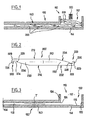
- the deployable structure essentially comprises guide means 100 and deployable elements 200. It furthermore comprises a drive system.
- the guiding means 100 comprise a trunk 110 and a guide 150.
- the guide 150 opens into the trunk 110.
- the guide 150 is formed of two rails 152 parallel and symmetrical with respect to a plane passing through the direction of movement of the elements 200 in the guide. These slides 152 are designed to receive and guide respectively the lateral edges of the elements 200.
- the invention also applies to variants according to which the structure comprises a single slideway 152 (then typically arranged not on a lateral edge of the elements 200 but on the middle part thereof), or comprises a number of slides 152 greater than two, or alternatively according to which the slide or the slides 152 receive a part of the elements 200 different from their side edge.
- each slideway 152 comprises a rectilinear channel having a cross section of constant width.
- each slide 152 may have a profile not rectilinear, but at least slightly curved.
- each slideway 152 viewed transversely to the direction of movement of the elements 200 is complementary to that of the elements 200.
- the guide 150 prohibits any relative displacement between two adjacent blades 200 in a direction transverse to the direction of the guide.
- the mechanical connection between the adjacent blades 200, in the longitudinal direction of the guide 150, is provided by the attachment means 220 themselves.
- the trunk 110 defines a housing 112 which extends essentially in a direction transverse to the slides 152.
- the guide 150 opens into the bottom of the box 110.
- the latter 110 has a bottom wall 114 which is substantially in the extension of a wall 153 of the guide 150.
- each slide 152 thus extends the bottom wall 114 of the box 110.
- the trunk 110 is delimited, in addition to the aforementioned bottom wall 114, by two sides 120 parallel to each other and parallel to the direction of movement of the elements 200 in both the guide 150 and the trunk 110 (one of these flanks 120 is visible on the Figures 1 and 3 ), by a downstream wall 122 transverse to the direction of movement of the elements 200 in the guide 150 but parallel to the direction of movement of the elements 200 in the trunk 110 and an upstream wall 124 parallel to the downstream wall 122.
- the guide 150 is connected to the upstream wall 124. Obviously it is perforated facing the guide 150 to allow the latter to open into the trunk 110.
- junction zone between the inner channel of the guide 150 and this upstream wall 124 preferably has a chamfer 126.
- Guiding elements having an oblique disposition with respect to the longitudinal direction of the guide 150 have previously been mentioned, adapted to impose on the deployable elements 200, in the box 110, a component transverse to the longitudinal direction of the guide.
- such oblique guide elements are formed by a partial inclination of the inner surface of the bottom wall 114 of the box 110. More precisely still such guide elements are formed by an inclined portion 116. This is preferably plane . It is formed on the part of the bottom wall 114 farthest from the guide 150. The inclined face 116 deviates from the axis of the slide 152 in the direction of a distance from the latter. The inclination between the pan 116 and the axis of the slide 152 is typically a few degrees.
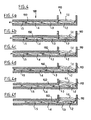
- the location, the length and the inclination of the inclined face 116 are adapted so that, as seen on the figure 4c which will be described in more detail later, when a blade L2 rests integrally on the panel 116, its upstream attachment structure 226 slightly interferes with the downstream structure 226 complementary to the adjacent blade L3 located in the slide 150. These structures 226 are engaged when the blade L3 or the blade L2 is biased outwardly of the trunk 110. On the contrary, the attachment structures 226 are disengaged when the blade L3 is urged towards the inside of the trunk 110.
- the length of the guide 150 is adapted to fully receive the elements 200 in juxtaposed position by their edge.
- the guide 150 may have a limited length, less than the expanded amplitude of all the elements 200, provided that means are provided capable of ensuring relative immobilization of the elements 200 outside the box 110. .
- the latter meanwhile is adapted to receive all the elements 200 in stacked position in which the elements 200 are adjacent by their main lateral faces.
- the deployable elements 200 are formed of elongate blades in a direction orthogonal to the direction of movement of the elements 200 in the guide 150.
- the elements 200 may have an extension limited transversely to the direction of the guide 150 and on the contrary have a significant extension in the direction of this guide 150 to form antenna type structures.
- FIG 2 a side view of a deployable element 200 in a view orthogonal to its direction of movement in the guide 150.
- all the elements 200 composing the same structure are identical. However, it is conceivable to combine in the same structure 200 different elements, especially as to their dimensions and their functions.
- the element 200 furthest forward, in the direction of deployment, in the guide 150 may be different from the other elements 200 and may constitute a covering part, at least since it does not require means for mutual engagement. with another element, only on its downstream edge.
- the elements 200 are formed of solid and opaque partitions. This arrangement is however not necessary for all applications. In the context of the present invention, it is thus possible to envisage making most of the body of the elements 200 using widely openwork panels.
- each element 200 has a central body 210 defined essentially by two main faces 212, 214 planar and parallel to each other.
- Each element 200 has at each of its slices perpendicular to the direction of movement in the guide 150, fastening means 220. These means 220 are intended to ensure mutual engagement of each pair of two elements 200 when they are arranged outside the box 110.
- Such attachment means 220 may be the subject of many embodiments.
- They can be continuous along the entire length of the blades 200 or only partial, limited to a part of the length of the blades 200.
- the attachment means 220 define two grooves 222, 224 which open respectively on opposite faces 212, 214 of the elements 200.
- downstream groove 222 that is to say the one that first enters the trunk 110
- upstream groove 224 that is to say the one which enters last in the chest 110
- these grooves 222, 224 are symmetrical to each other.
- each element 200 comprises an intermediate section 230 between the central body 210 with parallel faces and the grooves 222, 224.
- Each intermediate section 230 is delimited on the one hand by a plane facet 232 which extends one of the main faces 212, 214 respectively of the body 210, and an oblique face 234. The latter diverges with respect to the face 212, 214 on which opens the groove 222, 224 towards it.
- the attachment means constituted by the grooves 222, 224 define a non-parallel connection to the longitudinal direction of the guide 150, for example a perpendicular connection or oblique to this direction.
- each groove 222, 224 has a cross section generally U. It is delimited on the outside (which corresponds to the edge of the blades 200) by a wall 226 whose height (considered in a direction orthogonal to the faces 212, 214) is greater than the corresponding height of the wall 228 of the grooves adjacent to the oblique sections 234.
- This provision is intended to ensure on the one hand that the walls 226 escape the facing wall 228 respectively associated blades, thanks to the inclined portion 116 during stacking in the trunk 110, and secondly to ensure that the walls 226 of two adjacent blades instead engage, during deployment in the guide 150.
- each groove 222, 224 considered parallel to the direction of movement of the blades 200 in the guide 150, is typically complementary to the width of the walls 226 so that in the deployed position in the guide 150 each wall 226 of a blade 200 can penetrate into the complementary groove 222, 224 of an adjacent blade, without play in the direction of the guide 150 apart from the functional clearance necessary for the engagement of the walls 226 in the grooves 222, 224 and necessary for the movement of the set of blades 200 in the guide 150.
- This last feature allows on the one hand a great resistance against intrusion attempts since it prohibits a forced folding blades 200. It also allows a simple drive 200 blades since it allows to act on one only and any of the blades 200 located outside the trunk 110 for deployment or folding.
- the sum of the height of a wall 226 and the thickness of the groove bottom wall 222, 224 is equal to the thickness of the blades 200.
- each blade 200 has a rounding 229 on its edge which corresponds to the angle of the edge opposite the face on which the grooves 222, 224 open.
- the blades 200 further comprise, at the level of said attachment means 220, complementary fastening means 220A capable of ensuring immobilization between two adjacent deployable elements 200, in a direction transverse to the direction of the guide 150 and in position engaging engagement means 220.
- Such complementary attachment means 220A are provided with a certain clearance J allowing their disengagement and that of the attachment means 220 during the folding of the blades 200 of the structure in the trunk 110.
- Such complementary attachment means 220A also make it possible to envisage their activation ( Figures 5b, 6b ) or their deactivation ( Figures 5a, 6a ) in the deployed position of the deployable elements 200, this intervening on the relative position of these deployable elements 200 avoiding or ensuring the game J.
- the attachment means 220 define walls 226 and grooves 222, 224 associated, which are not orthogonal to the main faces 212 and 214 of the blades but which are inclined relative thereto for example at 45 °.
- the downstream portion of the blades 200 diverges, then, relative to the bottom wall 114 of the trunk 110 in the vicinity of the slideway 152.
- the slice upstream 200 blades diverges from the bottom wall 114 of the trunk 110 towards the slide 150.
- the blades 200 can be formed of solid material having a constant section.
- the blades 200 have groove structures 222, 224 identical to those visible on the figure 2 , over their entire length.
- the groove structures 222, 224 may be limited to a portion of the length of the blades 200.
- groove structures 222, 224 are then preferably provided adjacent each of the ends of the blades 200 intended to cooperate. with the guides 150.
- the blades 200 may be formed of solid monoblock element.
- the blades 200 can be formed by assembling different components.
- It may be for example the assembly of a central body, for example a body made by extrusion, and two end caps engaged on the ends thereof.
- the means forming the grooves 222, 224 may be provided either on the central body or on the end pieces.
- It may be for example a central body formed by assembling two side panels on longitudinal members defining the groove structures 222, 224 with the interposition of an air gap, or even a material presenting good sound and / or thermal insulation properties between the two panels.
- They may be formed of any suitable material, in particular plastic and / or metal, for example aluminum.
- the drive means of the blades 200 may be the subject of many embodiments. It can be manual or motorized drive means. These drive means are adapted to engage at least one of the blades 200 at the outlet of the box 110 to impose on it a displacement in the guide 150, alternately in the direction of deployment in the guide 150 or on the contrary in the sense of a stack in the trunk 110.
- the drive means may comprise a pinion driven to rotate about its fixed axis at the outlet of the box 110 and adapted to engage (via a rack provided on each blade 200) with the 200 blade adjacent to the bottom of the trunk 110.
- the pinion is successively engaged with the different blades as they progress.
- the drive means may be adapted to engage with the outermost blade 200, ie the blade that is furthest forward in the direction of deployment, in the guide 150.
- the direction of translation of the blades 200 in the guide 150 is referenced T on the figure 3 .
- the stacking or stacking of the blades 200 in the trunk 110 from the position illustrated on the figure 4a is performed as follows.
- a blade LI is illustrated in the stacked position in the trunk 110.
- the next blade L2 is in extended longitudinal position, as the following blades L3, L4 and L5.
- the blade L2 is thus engaged through its attachment means 226 with the attachment means 222 of the blade L3.
- the blade L2 is placed in an intermediate position between the guide 150 and the bottom of the box 110.
- the figure 4b shows that the longitudinal displacement of the blades 200, in the direction of elongation of the guide 150, associated with the presence of the chamfer 126, the rounded 229 and the oblique pan 116 allows the rotation of the blade L2 when it is urged towards this oblique end 116 by the biasing means 300.
- the figure 4c shows the blade L2 bears against the oblique pan 116. Its longitudinal movement is blocked by the wall 122 of the box. The pivoting of the blade L2 ensures the disengagement of its attachment means 226 and the attachment means 222 of the adjacent blade L3. Note that during the inversion of the movement and therefore the deployment, the walls 226 on the contrary come into engagement to allow the attachment of the blades.
- the figure 4d shows that the movement continues by the lifting of the blade L2 by the blade L3 through the oblique pan 234, accompanied by a relative movement in the direction of the slide 152 between the blades L2 and L3.
- the figure 4e shows the blade L3 taking position under the blade L2.
- the figure 4f shows that the blade L3 has taken the initial position of the blade L2. A complete stacking cycle of a blade 200 is thus completed.
- the removal of a blade 200 is performed according to the reverse kinematics.
- the width of the guide 150 being complementary to the thickness of the blades 200 and the width of the grooves 222, 224 being complementary to the width of the walls 226, any relative movement between the attachment means 222/224/226 of two adjacent deployable elements 200, is prohibited, when they are positioned outside the trunk 110, regardless of the direction of movement of the expandable elements in the guide.
- the device according to the present invention offers many advantages over the known provisions of the prior art.
- the present invention makes it possible in particular a limited overall bulk because it makes it possible to limit the volume of the box 110 to the total volume of the blades 200.
- the present invention allows a significant thickness of the blades. It thus makes it possible, in particular, to integrate any desirable function into the thickness of the blades, for example to give them a showcase function or to integrate them with active anti-intrusion means. It also makes it easy to achieve any sound and / or thermal insulation sought and offers great resistance against intrusion attempts.
- the present invention allows a good cohesion in traction (direction of deployment) and in compression (refolding direction) between the blades 200.
- the present invention provides a great simplicity of operation (absence of cable, chain or counterweight).
- the present invention is not limited as to its applications. It includes in particular the realization of shutters type shutters. However, it is not limited to this application.
- the present invention can thus be applied to any structure deployable in a vertical direction, horizontal, or even inclined both vertically and horizontally, to any large structure or wall to be stored in a restricted volume, and thus notably to the realization of telescopic mats, retractable partitions, movable floors, closures, berries, etc ...
Landscapes
- Engineering & Computer Science (AREA)
- Structural Engineering (AREA)
- Architecture (AREA)
- Civil Engineering (AREA)
- Operating, Guiding And Securing Of Roll- Type Closing Members (AREA)
- Packaging Of Annular Or Rod-Shaped Articles, Wearing Apparel, Cassettes, Or The Like (AREA)
- Sheets, Magazines, And Separation Thereof (AREA)
- Drawers Of Furniture (AREA)
Claims (25)
- Ausfahrbare Konstruktion der Art umfassend unabhängige ausfahrbare Elemente (200) und Führungsmittel (100), umfassend, einerseits, einen Kasten (110), geeignet, um die ausfahrbaren Elemente (200) gestapelt aufzunehmen, und, andererseits, eine Führung (150), die in dem Kasten (110) ausläuft und die angepasst ist, um die ausfahrbaren Elemente (200) nebeneinander angeordnet aufzunehmen, wobei die ausfahrbaren Elemente (200) Mittel zur gegenseitigen Kupplung (220) an ihren Rändern quer zu der Bewegungsrichtung der ausfahrbaren Elemente (200) in der Führung (150) umfassen, wobei sie, einerseits, Mittel (150), geeignet, um eine relative Bewegung zwischen den Kupplungsmitteln (220) von zwei angrenzenden ausfahrbaren Elementen (200), wenn sich diese außerhalb des Kastens (110) befinden, ungeachtet der Bewegungsrichtung der ausfahrbaren Elemente (200) in der Führung (150), zu verhindern, und, andererseits, Führungselemente (116) umfasst, die eine hinsichtlich der Längsrichtung der Führung (150) schrägliegende Anordnung aufweisen und angepasst sind, um den ausfahrbaren Elementen (200) in dem Kasten (110) eine Kraftkomponente quer zu der Längsrichtung der Führung (150) aufzuerlegen, dadurch gekennzeichnet, dass diese schrägliegende Führungselemente durch eine partielle Neigung (116) der inneren Oberfläche der Bodenwand (114) des Kastens (110) gebildet sind, in dem die Führung (150) ausläuft.
- Konstruktion nach Anspruch 1, dadurch gekennzeichnet, dass der gerade Abschnitt (154) der Führung (150), betrachtet quer zu der Bewegungsrichtung der Elemente (200), zu jenem der Elemente (200) ergänzend ist, derart, dass die Führung (150) jede Relativbewegung zwischen zwei benachbarten Leisten (200) in einer Richtung quer zu der Richtung der Führung verhindert, wenn die Kupplungsmittel in Eingriff sind.
- Konstruktion nach einem der Ansprüche 1 oder 2, dadurch gekennzeichnet, dass die Kupplungsmittel (220) eine mechanische Verbindung zwischen den benachbarten Elementen (200) in der Längsrichtung der Führung (150) sichern.
- Konstruktion nach einem der Ansprüche 1 bis 3, dadurch gekennzeichnet, dass der Kasten (110) federnde Mittel (300) beherbergt, die geeignet sind, um die Elemente (200) zu beanspruchen, die gegen die Bodenwand (114) des Kastens aufgestapelt sind.
- Konstruktion nach einem der Ansprüche 1 bis 4, dadurch gekennzeichnet, dass die Länge der Führung (150) angepasst ist, um die Elemente (200) nebeneinander angeordnet durch ihre Ränder vollständig aufzunehmen.
- Konstruktion nach einem der Ansprüche 1 bis 4, dadurch gekennzeichnet, dass die Führung (150) eine Länge besitzt, die kleiner ist als der Ausschlagbereich in Entfaltung der Gesamtheit der Elemente (200).
- Konstruktion nach einem der Ansprüche 1 bis 6, dadurch gekennzeichnet, dass die ausfahrbaren Elemente (200) durch Lamellen gebildet sind, die in einer Richtung rechtwinklig zu der Bewegungsrichtung der Elemente (200) in der Führung (150) verlängert sind.
- Konstruktion nach einem der Ansprüche 1 bis 6, dadurch gekennzeichnet, dass die ausfahrbaren Elemente (200) eine Ausdehnung haben, die quer zu der Richtung der Führung (150) begrenzt ist, und, im Gegenteil, eine erhebliche Ausdehnung in der Richtung dieser Führung (150) besitzen.
- Konstruktion nach einem der Ansprüche 1 bis 8, dadurch gekennzeichnet, dass die ausfahrbaren Elemente (200) durch massive und undurchsichtige Trennwände gebildet sind.
- Konstruktion nach einem der Ansprüche 1 bis 9, dadurch gekennzeichnet, dass die ausfahrbaren Elemente (200) durch den Zusammenbau verschiedener Bestandteile gebildet sind.
- Konstruktion nach einem der Ansprüche 1 bis 10, dadurch gekennzeichnet, dass die ausfahrbaren Elemente (200) durch den Zusammenbau eines zentralen Körpers, zum Beispiel eines Körpers, der durch Extrusion hergestellt ist, und zweier Ansatzstücke an den Enden desselben gebildet sind.
- Konstruktion nach einem der Ansprüche 1 bis 11, dadurch gekennzeichnet, dass die ausfahrbaren Elemente (200) einen zentralen Körper umfassen, der durch den Zusammenbau von zwei Seitenwänden an Längsträgern gebildet ist.
- Konstruktion nach einem der Ansprüche 1 bis 12, dadurch gekennzeichnet, dass die Kupplungselemente (220) sich auf der ganzen Länge der ausfahrbaren Elemente (200) erstrecken.
- Konstruktion nach einem der Ansprüche 1 bis 12, dadurch gekennzeichnet, dass die Kupplungselemente (220) sich auf nur einem Teil der Länge der ausfahrbaren Elemente (200) erstrecken.
- Konstruktion nach einem der Ansprüche 1 bis 14, dadurch gekennzeichnet, dass die Kupplungsmittel eine Verbindung bilden, die zu der Längsrichtung der Führung (150) nicht parallel ist.
- Konstruktion nach einem der Ansprüche 1 bis 15, dadurch gekennzeichnet, dass die Kupplungsmittel eine Verbindung bilden, die zu der Längsrichtung der Führung (150) senkrecht ist.
- Konstruktion nach einem der Ansprüche 1 bis 15, dadurch gekennzeichnet, dass die Kupplungsmittel eine Verbindung bilden, die hinsichtlich der Längsrichtung der Führung (150) schräg ist.
- Konstruktion nach einem der Ansprüche 1 bis 17, dadurch gekennzeichnet, dass die Kupplungsmittel zwei Nuten (222, 224) bilden, die entsprechend an gegenüberliegenden Seiten (212, 214) der Elemente (200), und somit entsprechend an jedem Ende der Elemente (200) auslaufen.
- Konstruktion nach Anspruch 18, dadurch gekennzeichnet, dass jede Nut (222, 224) einen im allgemeinen U-förmigen Querschnitt besitzt und auf der Außenseite durch eine Trennwand (226) abgegrenzt ist, deren Höhe größer ist als die Höhe der inneren Wand (228) der Nuten.
- Konstruktion nach einem der Ansprüche 1 bis 19, dadurch gekennzeichnet, dass sie Mittel zum manuellen Antrieb der Lamellen (200) umfasst.
- Konstruktion nach einem der Ansprüche 1 bis 19, dadurch gekennzeichnet, dass sie Mittel zum motorisierten Antrieb der Lamellen (200) umfasst.
- Konstruktion nach einem der Ansprüche 1 bis 21, dadurch gekennzeichnet, dass sie Antriebsmittel umfasst, die angepasst sind, um mit wenigstens einer der Lamellen (200) am Ausgang des Kastens (110) in Eingriff gebracht zu werden, um dieser eine Bewegung in der Führung (150), bzw. in der Richtung einer Entfaltung in der Führung (150) oder, im Gegenteil, in der Richtung einer Aufstapelung in dem Kasten (110), zu erteilen.
- Konstruktion nach einem der Ansprüche 1 bis 22, dadurch gekennzeichnet, dass sie Antriebsmittel umfasst, die geeignet sind, um mit dem Element (200) in Eingriff gebracht zu werden, das dem Boden des Kastens (110) benachbart ist.
- Konstruktion nach einem der Ansprüche 1 bis 22, dadurch gekennzeichnet, dass sie Antriebsmittel umfasst, die angepasst sind, um mit dem äußersten Element (200) in Eingriff gebracht zu werden.
- Konstruktion nach einem der Ansprüche 1 bis 24, dadurch gekennzeichnet, dass sie im Bereich der Kupplungsmittel (220) ergänzende Kupplungsmittel (220A) umfasst, die geeignet sind, um eine Immobilisierung zwischen zwei benachbarten ausfahrbaren Elementen (200), und zwar in einer Richtung quer zu der Richtung der Führung (150) und in Eingriffstellung der Kupplungsmittel, zu sichern.
Applications Claiming Priority (3)
| Application Number | Priority Date | Filing Date | Title |
|---|---|---|---|
| FR0204315 | 2002-04-08 | ||
| FR0204315A FR2838156B1 (fr) | 2002-04-08 | 2002-04-08 | Structure deployable |
| PCT/FR2003/001105 WO2003091527A1 (fr) | 2002-04-08 | 2003-04-08 | Structure deployable |
Publications (2)
| Publication Number | Publication Date |
|---|---|
| EP1492932A1 EP1492932A1 (de) | 2005-01-05 |
| EP1492932B1 true EP1492932B1 (de) | 2008-06-18 |
Family
ID=28052173
Family Applications (2)
| Application Number | Title | Priority Date | Filing Date |
|---|---|---|---|
| EP03740578A Expired - Lifetime EP1492932B1 (de) | 2002-04-08 | 2003-04-08 | Ausfahrbare konstruktion |
| EP03745833.8A Expired - Lifetime EP1492933B1 (de) | 2002-04-08 | 2003-04-08 | Ausziehbare konstruktion |
Family Applications After (1)
| Application Number | Title | Priority Date | Filing Date |
|---|---|---|---|
| EP03745833.8A Expired - Lifetime EP1492933B1 (de) | 2002-04-08 | 2003-04-08 | Ausziehbare konstruktion |
Country Status (6)
| Country | Link |
|---|---|
| EP (2) | EP1492932B1 (de) |
| AU (2) | AU2003246795A1 (de) |
| DE (1) | DE60321671D1 (de) |
| ES (2) | ES2307952T3 (de) |
| FR (1) | FR2838156B1 (de) |
| WO (2) | WO2003091527A1 (de) |
Families Citing this family (2)
| Publication number | Priority date | Publication date | Assignee | Title |
|---|---|---|---|---|
| FR2917113A1 (fr) | 2007-06-05 | 2008-12-12 | Bubendorff Sa | Structure deployable. |
| WO2011120781A1 (de) * | 2010-04-01 | 2011-10-06 | Inventio Ag | Schiebetür mit stapelbaren paneelen |
Family Cites Families (11)
| Publication number | Priority date | Publication date | Assignee | Title |
|---|---|---|---|---|
| DE535570C (de) | 1931-10-12 | Emil Wittmer | Schiebeladen mit in schraegen Fuehrungsbahnen aufgehaengyten Einzelteilen | |
| GB697405A (en) * | 1950-05-15 | 1953-09-23 | Goldner Richard | Improved shutter, window or the like |
| FR2414613A1 (fr) | 1978-01-16 | 1979-08-10 | Souchier Georges | Perfectionnements apportes aux systemes d'obturation d'ouvertures, telles que notamment baies, fenetres et similaires |
| GB2023685A (en) | 1978-06-27 | 1980-01-03 | Agopyan B | Retractable roofing |
| FR2506381A1 (fr) | 1981-05-25 | 1982-11-26 | Choulet Louis | Dispositif d'obturation des baies constitue de lames a forte epaisseur |
| FR2560278A1 (fr) | 1984-02-27 | 1985-08-30 | Lescure Gilles | Panneau a lames, tel que volet a lames, notamment pour l'obturation d'ouvertures murales |
| IT1182740B (it) | 1985-06-05 | 1987-10-05 | Pillar Naco Ind | Struttura, a lamelle inclinabili ed orientabili, con clips portalamelle modulari e sfilabili |
| CH674238A5 (de) | 1987-12-22 | 1990-05-15 | Schenker Emil Ag | |
| US5957185A (en) | 1997-01-28 | 1999-09-28 | Robinson; Jeffry T. | Deployable and stackable accordion shutter system |
| FR2769040B1 (fr) | 1997-09-26 | 2000-03-17 | Fermetures Pallaud | Persiennes coulissantes destinees a la fermeture de fenetres portes-fenetres ou portes |
| US6339905B1 (en) * | 1998-07-20 | 2002-01-22 | Clark Craig | Hingeless, parallel storing, sectional aperture covering |
-
2002
- 2002-04-08 FR FR0204315A patent/FR2838156B1/fr not_active Expired - Fee Related
-
2003
- 2003-04-08 DE DE60321671T patent/DE60321671D1/de not_active Expired - Lifetime
- 2003-04-08 AU AU2003246795A patent/AU2003246795A1/en not_active Abandoned
- 2003-04-08 WO PCT/FR2003/001105 patent/WO2003091527A1/fr not_active Ceased
- 2003-04-08 EP EP03740578A patent/EP1492932B1/de not_active Expired - Lifetime
- 2003-04-08 WO PCT/FR2003/001102 patent/WO2003085229A1/fr not_active Ceased
- 2003-04-08 EP EP03745833.8A patent/EP1492933B1/de not_active Expired - Lifetime
- 2003-04-08 ES ES03740578T patent/ES2307952T3/es not_active Expired - Lifetime
- 2003-04-08 AU AU2003263322A patent/AU2003263322A1/en not_active Abandoned
- 2003-04-08 ES ES03745833.8T patent/ES2546958T3/es not_active Expired - Lifetime
Also Published As
| Publication number | Publication date |
|---|---|
| ES2546958T3 (es) | 2015-09-30 |
| FR2838156B1 (fr) | 2004-09-03 |
| ES2307952T3 (es) | 2008-12-01 |
| WO2003085229A1 (fr) | 2003-10-16 |
| AU2003263322A1 (en) | 2003-11-10 |
| WO2003091527A1 (fr) | 2003-11-06 |
| EP1492932A1 (de) | 2005-01-05 |
| EP1492933A1 (de) | 2005-01-05 |
| EP1492933B1 (de) | 2015-06-17 |
| FR2838156A1 (fr) | 2003-10-10 |
| DE60321671D1 (de) | 2008-07-31 |
| AU2003246795A1 (en) | 2003-10-20 |
Similar Documents
| Publication | Publication Date | Title |
|---|---|---|
| EP2231978B1 (de) | Verschlussvorrichtung mit mindestens einem ziehharmonikaartig gefalteten verschluss | |
| CA2675649C (fr) | Dispositif a rideau flexible | |
| CA2835351C (fr) | Dispositif d'obturation au moins partielle d'une cavite ouverte par le dessus | |
| CA2675648C (fr) | Dispositif a rideau enroulable | |
| CA2041393A1 (fr) | Systeme d'articulation de panneaux et application aux portes sectionnelles | |
| EP0224290A1 (de) | Bauart einer abdeckbaren Bedachung | |
| EP2900893B2 (de) | Transparenter rollladen | |
| EP0483282A1 (de) | Tür mit mehreren schiebeflügeln. | |
| EP1680571B1 (de) | Schnelltür mit doppelter abschirmung | |
| EP1492932B1 (de) | Ausfahrbare konstruktion | |
| EP2148040B1 (de) | Behangvorrichtung insbesondere für Verdunkelungssystem und/oder Gebäudeverschlusssystem | |
| EP0818601A1 (de) | Rolladen mit dünnen lamellen, die zusammengefügt und mit geraden Kanten versehen sind | |
| FR2970996A1 (fr) | Joint pour ouvrant et ouvrant equipe d'un tel joint. | |
| FR2935406A1 (fr) | Abri telescopique guide en partie haute | |
| EP2048320B1 (de) | Rollladen beinhaltend einen Behang für ein Abdecksystem mit verstellbaren Lamellen | |
| FR2765616A1 (fr) | Perfectionnements a des volets roulants | |
| FR3020651A1 (fr) | Abri de piscine comprenant un volet mobile | |
| EP1672163B1 (de) | Einrichtung zum Sichern der Rolladenstäbe eines Rolladen in ihrer seitlichen Führung | |
| EP0965723B1 (de) | Rolladen für Tür, Fenster oder dergleichen | |
| WO2018011487A1 (fr) | Couverture d'isolation thermique pour couvrir une surface et installation pour sa mise en oeuvre | |
| FR2974330A1 (fr) | Vehicule utilitaire comprenant une cellule arriere avec une baie obturee par un store, et cellule arriere correspondante | |
| FR2885572A1 (fr) | Element de plancher de vehicule automobile et vehicule le comportant | |
| EP1772299A2 (de) | Aufleger mit einem Sattelzug | |
| EP2312111A1 (de) | Wärmeschutzvorrichtung für eine Gebäudeöffnung | |
| EP1605130A1 (de) | Fingerschutz |
Legal Events
| Date | Code | Title | Description |
|---|---|---|---|
| PUAI | Public reference made under article 153(3) epc to a published international application that has entered the european phase |
Free format text: ORIGINAL CODE: 0009012 |
|
| 17P | Request for examination filed |
Effective date: 20041006 |
|
| AK | Designated contracting states |
Kind code of ref document: A1 Designated state(s): AT BE BG CH CY CZ DE DK EE ES FI FR GB GR HU IE IT LI LU MC NL PT RO SE SI SK TR |
|
| AX | Request for extension of the european patent |
Extension state: AL LT LV MK |
|
| GRAP | Despatch of communication of intention to grant a patent |
Free format text: ORIGINAL CODE: EPIDOSNIGR1 |
|
| GRAS | Grant fee paid |
Free format text: ORIGINAL CODE: EPIDOSNIGR3 |
|
| GRAA | (expected) grant |
Free format text: ORIGINAL CODE: 0009210 |
|
| AK | Designated contracting states |
Kind code of ref document: B1 Designated state(s): DE ES FR GB IT |
|
| REG | Reference to a national code |
Ref country code: GB Ref legal event code: FG4D Free format text: NOT ENGLISH |
|
| REF | Corresponds to: |
Ref document number: 60321671 Country of ref document: DE Date of ref document: 20080731 Kind code of ref document: P |
|
| REG | Reference to a national code |
Ref country code: ES Ref legal event code: FG2A Ref document number: 2307952 Country of ref document: ES Kind code of ref document: T3 |
|
| PLBE | No opposition filed within time limit |
Free format text: ORIGINAL CODE: 0009261 |
|
| STAA | Information on the status of an ep patent application or granted ep patent |
Free format text: STATUS: NO OPPOSITION FILED WITHIN TIME LIMIT |
|
| 26N | No opposition filed |
Effective date: 20090319 |
|
| PGFP | Annual fee paid to national office [announced via postgrant information from national office to epo] |
Ref country code: GB Payment date: 20120419 Year of fee payment: 10 |
|
| GBPC | Gb: european patent ceased through non-payment of renewal fee |
Effective date: 20130408 |
|
| PG25 | Lapsed in a contracting state [announced via postgrant information from national office to epo] |
Ref country code: GB Free format text: LAPSE BECAUSE OF NON-PAYMENT OF DUE FEES Effective date: 20130408 |
|
| REG | Reference to a national code |
Ref country code: DE Ref legal event code: R082 Ref document number: 60321671 Country of ref document: DE Representative=s name: PATENTANWAELTE UND RECHTSANWALT DR. WEISS, ARA, DE Ref country code: DE Ref legal event code: R082 Ref document number: 60321671 Country of ref document: DE Representative=s name: PATENTANWAELTE UND RECHTSANWALT WEISS, ARAT & , DE |
|
| REG | Reference to a national code |
Ref country code: FR Ref legal event code: PLFP Year of fee payment: 14 |
|
| REG | Reference to a national code |
Ref country code: FR Ref legal event code: PLFP Year of fee payment: 15 |
|
| REG | Reference to a national code |
Ref country code: FR Ref legal event code: PLFP Year of fee payment: 16 |
|
| PGFP | Annual fee paid to national office [announced via postgrant information from national office to epo] |
Ref country code: IT Payment date: 20220426 Year of fee payment: 20 Ref country code: FR Payment date: 20220404 Year of fee payment: 20 Ref country code: ES Payment date: 20220608 Year of fee payment: 20 Ref country code: DE Payment date: 20220429 Year of fee payment: 20 |
|
| REG | Reference to a national code |
Ref country code: DE Ref legal event code: R071 Ref document number: 60321671 Country of ref document: DE |
|
| REG | Reference to a national code |
Ref country code: ES Ref legal event code: FD2A Effective date: 20230427 |
|
| PG25 | Lapsed in a contracting state [announced via postgrant information from national office to epo] |
Ref country code: ES Free format text: LAPSE BECAUSE OF EXPIRATION OF PROTECTION Effective date: 20230409 |