EP1492973B1 - Durchflussregelventil mit integriertem sensor und regler - Google Patents
Durchflussregelventil mit integriertem sensor und regler Download PDFInfo
- Publication number
- EP1492973B1 EP1492973B1 EP03721582A EP03721582A EP1492973B1 EP 1492973 B1 EP1492973 B1 EP 1492973B1 EP 03721582 A EP03721582 A EP 03721582A EP 03721582 A EP03721582 A EP 03721582A EP 1492973 B1 EP1492973 B1 EP 1492973B1
- Authority
- EP
- European Patent Office
- Prior art keywords
- valve
- coupled
- passageway
- pressure
- variable area
- Prior art date
- Legal status (The legal status is an assumption and is not a legal conclusion. Google has not performed a legal analysis and makes no representation as to the accuracy of the status listed.)
- Expired - Lifetime
Links
- 239000012530 fluid Substances 0.000 claims description 47
- 238000011144 upstream manufacturing Methods 0.000 claims description 27
- 230000003068 static effect Effects 0.000 claims description 2
- 238000005259 measurement Methods 0.000 description 6
- 238000000034 method Methods 0.000 description 6
- 238000013461 design Methods 0.000 description 3
- 230000009977 dual effect Effects 0.000 description 2
- 230000000903 blocking effect Effects 0.000 description 1
- 238000010276 construction Methods 0.000 description 1
- 230000007423 decrease Effects 0.000 description 1
- 230000001419 dependent effect Effects 0.000 description 1
- 230000000694 effects Effects 0.000 description 1
- 239000007788 liquid Substances 0.000 description 1
- 238000012423 maintenance Methods 0.000 description 1
- 239000000463 material Substances 0.000 description 1
- 238000012986 modification Methods 0.000 description 1
- 230000004048 modification Effects 0.000 description 1
- 230000003287 optical effect Effects 0.000 description 1
Images


Classifications
-
- G—PHYSICS
- G01—MEASURING; TESTING
- G01F—MEASURING VOLUME, VOLUME FLOW, MASS FLOW OR LIQUID LEVEL; METERING BY VOLUME
- G01F1/00—Measuring the volume flow or mass flow of fluid or fluent solid material wherein the fluid passes through a meter in a continuous flow
- G01F1/05—Measuring the volume flow or mass flow of fluid or fluent solid material wherein the fluid passes through a meter in a continuous flow by using mechanical effects
- G01F1/34—Measuring the volume flow or mass flow of fluid or fluent solid material wherein the fluid passes through a meter in a continuous flow by using mechanical effects by measuring pressure or differential pressure
- G01F1/36—Measuring the volume flow or mass flow of fluid or fluent solid material wherein the fluid passes through a meter in a continuous flow by using mechanical effects by measuring pressure or differential pressure the pressure or differential pressure being created by the use of flow constriction
- G01F1/363—Measuring the volume flow or mass flow of fluid or fluent solid material wherein the fluid passes through a meter in a continuous flow by using mechanical effects by measuring pressure or differential pressure the pressure or differential pressure being created by the use of flow constriction with electrical or electro-mechanical indication
-
- G—PHYSICS
- G05—CONTROLLING; REGULATING
- G05D—SYSTEMS FOR CONTROLLING OR REGULATING NON-ELECTRIC VARIABLES
- G05D7/00—Control of flow
- G05D7/005—Control of flow characterised by the use of auxiliary non-electric power combined with the use of electric means
-
- Y—GENERAL TAGGING OF NEW TECHNOLOGICAL DEVELOPMENTS; GENERAL TAGGING OF CROSS-SECTIONAL TECHNOLOGIES SPANNING OVER SEVERAL SECTIONS OF THE IPC; TECHNICAL SUBJECTS COVERED BY FORMER USPC CROSS-REFERENCE ART COLLECTIONS [XRACs] AND DIGESTS
- Y10—TECHNICAL SUBJECTS COVERED BY FORMER USPC
- Y10T—TECHNICAL SUBJECTS COVERED BY FORMER US CLASSIFICATION
- Y10T137/00—Fluid handling
- Y10T137/0318—Processes
-
- Y—GENERAL TAGGING OF NEW TECHNOLOGICAL DEVELOPMENTS; GENERAL TAGGING OF CROSS-SECTIONAL TECHNOLOGIES SPANNING OVER SEVERAL SECTIONS OF THE IPC; TECHNICAL SUBJECTS COVERED BY FORMER USPC CROSS-REFERENCE ART COLLECTIONS [XRACs] AND DIGESTS
- Y10—TECHNICAL SUBJECTS COVERED BY FORMER USPC
- Y10T—TECHNICAL SUBJECTS COVERED BY FORMER US CLASSIFICATION
- Y10T137/00—Fluid handling
- Y10T137/7722—Line condition change responsive valves
- Y10T137/7758—Pilot or servo controlled
- Y10T137/7762—Fluid pressure type
- Y10T137/7764—Choked or throttled pressure type
Definitions
- the present invention relates to an apparatus for measuring and controlling fluid flow in a passageway and, more particularly, to an apparatus and method for measuring and controlling fluid flow through a variable area flow orifice within the passageway.
- Systems and methods for measuring and controlling fluid flow in a system are found in various industries.
- various air distribution systems in commercial aircraft use various devices for measuring and controlling the flow of air through numerous branch lines that feed different portions of the aircraft.
- the flow of air through these branch lines may be controlled by a control valve, in response to a flow rate measurement, (see for instance DE-A-100 01165 ).
- control valves presently known may be either mechanically complex or simple.
- One mechanically complex control valve may have a relatively heavy, complex, and expensive all mechanical servo valve that both measures and controls fluid flow rate.
- One mechanically simple control valve may have a simple, mechanical valve that is remotely actuated by a controller that uses either a venturi type flow sensor or a hot wire anemometer type flow sensor.
- the mechanically complex valve may have limited dynamic range and may be limited to one or two flow rate set points.
- the valve with a venturi type sensor may have limited dynamic range and may be relatively expensive.
- a hot wire anemometer may also be relatively expensive, may have poor accuracy, and may be limited to low temperature applications.
- the present invention provides an apparatus for measuring and controlling fluid flow through a variable area flow orifice that is relatively simple in design, is relatively inexpensive, is accurate, and has a wide measurement range.
- valve as defined in claim 1 is provided.
- Preferred embodiments of the invention are defined in the dependent claims.
- the present invention is not limited to the embodiment described herein.
- the present embodiment is, for convenience of explanation, depicted and described as a flow control valve with a system that is used to determine and control mass flow rate, it will be appreciated that it can be used to determine and control other fluid flow properties, such as volumetric flow rate and heat flow rate.
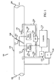
- the flow control valve 100 includes a passageway 102 that has an inlet opening 104 and an outlet opening 106.
- the fluid whose flow rate is being controlled flows into the inlet 104 and exits the outlet 106.
- the valve can be used to measure and control the flow rate of various types of fluid, including both liquids and gasses. In a preferred embodiment, however, the fluid is a gas, such as air.
- the flow rate of the fluid through the passageway 102 is controlled by a variable area flow orifice which, in the depicted embodiment is a butterfly valve gate 108.
- the butterfly valve gate 108 includes a valve disk 110 that is mounted on a shaft 112, which is in turn rotationally mounted within the passageway 102.
- the flow rate of the fluid through the passageway 102 may be varied by changing the angular position of the butterfly valve gate 108. Specifically, the butterfly valve gate 108 may be moved between a closed position where the disk 110 is oriented substantially perpendicular to the fluid flow path, thus blocking fluid flow through the passageway 102, and a fully-open position where the disk 110 is oriented substantially parallel to the fluid flow path, thus presenting less resistance to fluid flow through the passageway 102.
- other types of valves may be used to implement the variable area flow orifice including, but not limited to, poppet valves, ball valves, and sleeve valves.
- the position of the valve gate 108 is controlled by a valve actuator assembly 114 that receives a position control signal from a controller 116, the function of which is described in more detail below.
- the actuator assembly 114 may be any one of numerous valve actuation devices known in the art including an electric, pneumatic, or hydraulic actuator, which may be directly coupled to the shaft 112 or coupled to the shaft via one or more gears or linkages.
- the preferred actuator assembly 114 is an electro-pneumatic type of actuator that is coupled to the passageway 102 using a supply pressure conduit 121.
- the actuator assembly 114 includes an actuator piston assembly 202 and a torque motor 204 coupled together by a control pressure conduit 206.
- the preferred actuator piston assembly 202 includes a dual-faced piston 208 and a spring 210 mounted within an actuator housing 212.
- the piston 208 includes a first face 207 and a second face 209. As FIG. 2 depicts, the surface area of the first face 207 is larger than that of the second face 209.
- One or more links 214 are coupled between the second face 209 of the piston 208 and the shaft 112. These links 214, in response to movement of the piston 208, cause the shaft 112 to rotate, thereby positioning the valve disk 110.
- the piston housing 212 includes three ports, a first supply pressure port 216, a first ambient pressure port 218, and a first control pressure port 220.
- the first supply pressure port 216 is coupled to receive fluid pressure from upstream of the valve 108 and, in combination with the spring 210, biases the piston 208 upwardly, which biases the valve disk 110 to the closed position.
- the first control pressure port 220 receives a control pressure from the torque motor 204, via the control pressure conduit 206.
- the valve disk 110 is appropriately positioned.
- the pressure magnitude in the control pressure conduit 206 is controlled by the torque motor 204.
- the torque motor 204 may be any one of numerous designs known in the art. In the depicted embodiment, the torque motor 204 is enclosed in a housing 222.
- the torque motor housing 222 like the piston housing 212, includes three ports, a second supply pressure port 228, a second ambient pressure port 230, and a second control pressure port 232.
- the second supply pressure port 228 is coupled to receive fluid pressure from upstream of the valve 108, and may share a common line with the piston housing supply pressure port 216.
- the second ambient pressure port 230 vents the torque motor housing 222 to atmosphere, and the second control pressure port supplies a control pressure to the control pressure conduit 206.
- the torque motor 204 receives a control current from the controller 116 and, in response, controls the pressure magnitude supplied through the second control pressure port 232 between supply and ambient pressures.
- An increase in control current to the torque motor 204 will cause an increase in pressure magnitude in the control pressure conduit 206, which will cause the valve 108 to move toward the open position.
- the pressure magnitude in the control pressure conduit 206 increases. This will cause the valve 108 to move toward the closed position.
- Valve position is sensed by a valve position sensor 118, which supplies a position signal to the controller 116.
- the valve position sensor 118 may be any one of numerous devices known in the art for providing an indication of valve position including, but not limited to, a linear variable differential transformer (LVDT), a rotational variable differential transformer (RVDT), a potentiometer, or a piezoelectric sensor.
- LVDT linear variable differential transformer
- RVDT rotational variable differential transformer
- potentiometer a potentiometer
- piezoelectric sensor In the preferred embodiment the valve position sensor 118 is an RVDT.
- a temperature sensor 120 senses fluid temperature. This temperature may be physically sensed either upstream of the valve 108 or downstream of the valve 108. Preferably, the fluid temperature is sensed upstream of the valve 108; however, since the preferred method by which pressure is determined and controlled (discussed further below) is a function of the square root of the fluid temperature, sensing it downstream of the valve provides sufficient accuracy.
- the temperature 120 sensor may be any one of numerous temperature sensing devices known in the art including, but not limited to, a resistance temperature detector (RTD), a thermocouple, and an optical temperature sensor. In the preferred embodiment, however, the temperature sensor is an RTD.
- a pressure sensor 122 is coupled to the passageway 102 and senses fluid pressure within the passageway 102.
- the pressure sensor 122 may be coupled to the passageway 102 to sense pressure either upstream or downstream of the valve 108; however, in a preferred embodiment, the pressure sensor 122 is coupled to the passageway 102 to sense pressure upstream of the valve 108.
- the pressure sensor 120 may be configured to measure either total pressure or static pressure, and may be any one of numerous pressure sensing devices known in the art including, but not limited to, a capacitance sensor, a strain gauge sensor, and a thermal sensor. However, in the preferred embodiment the pressure sensor 120 is a piezoresistive sensor.
- a differential pressure sensor 124 is also coupled to the passageway 102 and is configured to sense the differential pressure across the valve 108.
- the differential pressure sensor 124 may be any one of numerous devices known in the art for sensing differential pressure, and may also be comprised of a single sensor or dual pressure sensors. However, in the preferred embodiment the differential pressure sensor 124 is a single piezoresistive sensor. It is noted that if the differential pressure sensor 124 is comprised of dual pressure sensors, one of the two pressure sensors could be pressure sensor 122. In this latter case, the skilled artisan will appreciate that the controller 116 would determine the differential pressure across the valve 108 based on the sensed upstream and downstream pressures.
- the differential pressure sensor 124 is coupled to the passageway 102 using two conduits, an upstream conduit 126 and a downstream conduit 128.
- the pressure sensor 122 is coupled to the passageway 102 using the upstream conduit 126, as well. It will be appreciated that the pressure sensor 122 could be coupled to the passageway 102 using a separate conduit. However, for space and component savings the pressure sensor 122 uses the upstream conduit 126.
- a flow venturi 130 is coupled to the downstream conduit 128 and is preferably positioned so that it is not within high fluid velocity streams when the valve 108 is near its closed position. As will be discussed in more detail below, the flow venturi 130 provides greater resolution of the differential pressure sensor signal at low fluid flow velocities. It will be appreciated that in an embodiment where the pressure sensor 122 is coupled to the passageway 102 downstream of the valve 108, the pressure sensor could share the downstream conpassageway 128 with the differential pressure sensor 124.
- the controller 116 Based on the determined actual flow rate, the controller 116 then supplies position control signals, as necessary, to the actuator assembly 114 so that the fluid flow rate through the passageway 102 is substantially equal to the commanded flow rate.
- downstream pressure and/or downstream temperature could be used as well.
- the flow venturi 130 is positioned downstream of the valve 108, as the valve 108 moves toward its full-open position, an increasing amount of fluid flows through the flow venturi 130.
- the flow venturi 130 effectively boosts the downstream pressure sensed by the differential pressure sensor 124 as the valve 108 moves toward its full-open position. As was alluded to above, this effect provides greater resolution of the differential pressure sensor signal at low fluid flow velocities.
- fluid flow through the passageway 102 can be determined quickly and accurately and all of the above-described components can be configure into a single, relatively compact control valve assembly.
- the sensors can be located relatively close to the valve 108 itself, and the controller 116 need not be located remotely from the valve 108.
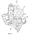
- An exemplary embodiment of one such control valve assembly is shown in FIGS. 3 , 4 , and 5 , which depict back end, front end, and side views, respectively, of the control valve assembly.
- the housing assembly 304 may be constructed as a single, integral unit or may be constructed of various interconnected housings. In a preferred embodiment, the housing assembly 304 is constructed of various interconnected housings. This type of construction eases assembly, maintenance, reuse, and repair of the control valve assembly 300.
- the housing assembly 304 preferably includes the actuator housing 212, the torque motor housing 222, a position sensor housing 308, a pressure sensor housing 310, and a controller housing 312.
- the actuator housing 212 houses the dual-faced piston 208 and spring 210, and includes the first supply pressure port 216, the first ambient pressure port 218, and the first control pressure port 220, all of which were previously described above.
- the torque motor housing 222 houses the electrical coils 224 and the pivotally mounted control shaft 226, and includes the second supply pressure port 228, the second ambient pressure port 230, and the second control pressure port 232.
- the position sensor housing 308 houses the valve position sensor 118 which, as was noted above, senses valve position and supplies a representative position signal to the controller 116.
- the pressure sensor housing 310 houses both the pressure sensor 122 and the differential pressure sensor 124.
- the controller housing 312 houses, among other things, the electrical components that comprise the controller 116. In particular, the controller housing 312 houses one or more circuit boards that have mounted thereon the electrical and electronic components that make up the controller 116. Although the controller 116 may be constructed of a plurality of individual circuit boards, in a preferred embodiment the controller 116 is constructed of a single, double-sided circuit board 314.
- the controller housing 312 also houses a thermoelectric (Peltier) cooler 316 that, as is generally known, to absorb heat from the circuit board 314 and reject it to the surrounding environment. As FIGS. 3 and 5 depict, the controller housing 312 also preferably includes a plurality of fins 318 to assist rejecting the heat from the controller housing 312.
- a thermoelectric (Peltier) cooler 316 that, as is generally known, to absorb heat from the circuit board 314 and reject it to the surrounding environment.
- the controller housing 312 also preferably includes a plurality of fins 318 to assist rejecting the heat from the controller housing 312.
- the present invention provides a flow control valve, and a method of determining and controlling fluid flow through the valve, that is relatively simple in design, is relatively inexpensive, is accurate, and is not limited in its measurement range. It also provides a flow control valve that is relatively compact and includes all of the flow measurement and control components in a single, relatively compact assembly.
Landscapes
- Physics & Mathematics (AREA)
- General Physics & Mathematics (AREA)
- Engineering & Computer Science (AREA)
- Fluid Mechanics (AREA)
- Power Engineering (AREA)
- Automation & Control Theory (AREA)
- Flow Control (AREA)
- Measuring Volume Flow (AREA)
Claims (10)
- Ventil zum Messen und Regeln eines Fluidstromparameters, das Folgendes umfasst:eine Ventilanordnung (108) mit einem Einlass (104), einem Auslass (106) und einem Durchgang (102) dazwischen;eine im Durchgang (102) angebrachte Durchflussöffnung (110) mit veränderlichem Querschnitt;einen Differenzdrucksensor (124), der zur Erfassung eines Differenzdrucks an der Durchflussöffnung (110) mit veränderlichem Querschnitt und zur Zuführung eines Differenzdrucksignals betreibbar ist;eine stromaufwärtige Leitung (126) mit einem Einlass, der mit dem Durchgang (102) stromaufwärts der Durchflussöffnung (110) mit veränderlichem Querschnitt verbunden ist, und einem Auslass, der mit dem Differenzdrucksensor (124) verbunden ist;eine stromabwärtige Leitung (128) mit einem Einlass, der mit dem Durchgang (102) stromabwärts der Durchflussöffnung (110) mit veränderlichem Querschnitt verbunden ist, und einem Auslass, der mit dem Differenzdrucksensor (124) verbunden ist;ein Strömungs-Venturirohr (130), das mit dem Einlass der stromabwärtigen Leitung (128) verbunden und nahe der Durchflussöffnung (110) mit veränderlichem Querschnitt positioniert ist;einen Drucksensor (122), der mit dem Durchgang (102) verbunden ist, wobei der Drucksensor (122) zur Erfassung von Fluiddruck in dem Durchgang (102) und zur Zuführung eines Fluiddrucksignals betreibbar ist;einen Temperatursensor (120), der mit dem Durchgang (102) verbunden und zur Erfassung von Fluidtemperatur und zur Zuführung eines Fluidtemperatursignals betreibbar ist;einen Positionssensor (118), der zur Erfassung einer Position der Durchflussöffnung (110) mit veränderlichem Querschnitt und zur Zuführung eines Positionssignals betreibbar ist; undeinen Prozessor (116), der zum Empfang des Differenzdrucksignals, des Fluiddrucksignals, des Fluidtemperatursignals und des Positionssignals gekoppelt und zur Bestimmung des Fluidstromparameters im Durchgang (102) davon betreibbar ist.
- Ventil nach Anspruch 1, wobei der Prozessor (116) ein Öffnungspositionssteuersignal auf Grundlage des bestimmten Fluidstromparameters erzeugt und wobei das Ventil weiterhin
eine Stellgliedanordnung (114) umfasst, die zum Empfang des Öffnungspositionssteuersignals von dem Prozessor (116) gekoppelt und so betreibbar ist, dass sie als Reaktion darauf einen Querschnitt der Durchflussöffnung (110) mit veränderlichem Querschnitt ändert, wobei der Fluidstromparameter durch den Durchgang (102) gesteuert wird. - Ventil nach Anspruch 1, wobei
die Durchflussöffnung (110) mit veränderlichem Querschnitt ein Drosselklappenventil ist, das über eine Welle (112) drehbar im Durchgang (102) angebracht ist; und
das Strömungs-Venturirohr (130) nahe der Welle (112) positioniert ist. - Ventil nach Anspruch 1, wobei der Drucksensor (122) ein Sensor zur Messung statischen Drucks ist.
- Ventil nach Anspruch 1, wobei der Drucksensor (122) ein Gesamtdrucksensor ist.
- Ventil nach Anspruch 2, wobei die Stellgliedanordnung (114) Folgendes umfasst:einen Drehmomentrotor (204), der zum Empfang der Öffnungspositionssteuersignale von dem Prozessor (116) gekoppelt und so betreibbar ist, dass er als Reaktion darauf eine Steuerdruckgröße in einer Steuerdruckleitung (206) ändert;ein Stellgliedgehäuse (212) mit mindestens einem Steuerdruckkanal (220), der mit der Steuerdruckleitung (206) verbunden ist; undeine Kolbenanordnung (202), die verschiebbar in dem Stellgliedgehäuse (212) angebracht ist, wobei die Kolbenanordnung (202) ein erstes Ende (207), das mit dem Steuerdruckkanal (220) in Strömungsverbindung steht, und ein zweites Ende (209), das mit der Durchflussöffnung (110) mit veränderlichem Querschnitt verbunden ist, aufweist,wobei eine Änderung der Steuerdruckgröße eine translatorische Verschiebung der Kolbenanordnung (202) und eine Änderung des Querschnitts der Durchflussöffnung (110) mit veränderlichem Querschnitt bewirkt.
- Ventil nach Anspruch 1, wobei der Temperatursensor (120) Fluidtemperatur stromaufwärts der Durchflussöffnung (110) mit veränderlichem Querschnitt erfasst.
- Ventil nach Anspruch 1, wobei der Temperatursensor (120) Fluidtemperatur stromabwärts der Durchflussöffnung (110) mit veränderlichem Querschnitt erfasst.
- Ventil nach Anspruch 1, wobei der Drucksensor (122) stromaufwärts der Durchflussöffnung (110) mit veränderlichem Querschnitt mit dem Durchgang (102) verbunden ist.
- Ventil nach Anspruch 1, wobei der Drucksensor (122) stromabwärts der Durchflussöffnung (110) mit veränderlichem Querschnitt mit dem Durchgang (102) verbunden ist.
Applications Claiming Priority (3)
| Application Number | Priority Date | Filing Date | Title |
|---|---|---|---|
| US10/119,686 US6892745B2 (en) | 2002-04-10 | 2002-04-10 | Flow control valve with integral sensor and controller and related method |
| US119686 | 2002-04-10 | ||
| PCT/US2003/010804 WO2003087642A1 (en) | 2002-04-10 | 2003-04-08 | Flow control valve with integral sensor and controller and related method |
Publications (2)
| Publication Number | Publication Date |
|---|---|
| EP1492973A1 EP1492973A1 (de) | 2005-01-05 |
| EP1492973B1 true EP1492973B1 (de) | 2009-04-01 |
Family
ID=28789966
Family Applications (1)
| Application Number | Title | Priority Date | Filing Date |
|---|---|---|---|
| EP03721582A Expired - Lifetime EP1492973B1 (de) | 2002-04-10 | 2003-04-08 | Durchflussregelventil mit integriertem sensor und regler |
Country Status (5)
| Country | Link |
|---|---|
| US (1) | US6892745B2 (de) |
| EP (1) | EP1492973B1 (de) |
| AU (1) | AU2003224889A1 (de) |
| DE (1) | DE60326944D1 (de) |
| WO (1) | WO2003087642A1 (de) |
Families Citing this family (65)
| Publication number | Priority date | Publication date | Assignee | Title |
|---|---|---|---|---|
| US20040099061A1 (en) * | 1997-12-22 | 2004-05-27 | Mks Instruments | Pressure sensor for detecting small pressure differences and low pressures |
| WO2004010234A2 (en) * | 2002-07-19 | 2004-01-29 | Celerity Group, Inc. | Methods and apparatus for pressure compensation in a mass flow controller |
| WO2004088190A1 (en) * | 2003-04-01 | 2004-10-14 | Monatec Pty Ltd | Valve monitoring method and arrangement |
| US7036794B2 (en) * | 2004-08-13 | 2006-05-02 | Vat Holding Ag | Method for control of a vacuum valve arranged between two vacuum chambers |
| US7201057B2 (en) * | 2004-09-30 | 2007-04-10 | Mks Instruments, Inc. | High-temperature reduced size manometer |
| US7141447B2 (en) * | 2004-10-07 | 2006-11-28 | Mks Instruments, Inc. | Method of forming a seal between a housing and a diaphragm of a capacitance sensor |
| US7137301B2 (en) * | 2004-10-07 | 2006-11-21 | Mks Instruments, Inc. | Method and apparatus for forming a reference pressure within a chamber of a capacitance sensor |
| FR2881536B1 (fr) * | 2005-02-03 | 2007-04-06 | Peugeot Citroen Automobiles Sa | Procede et dispositif d'asservissement de la position d'un obturateur de vanne |
| CN1318930C (zh) * | 2005-04-27 | 2007-05-30 | 杭州电子科技大学 | 智能执行器用阀门流量特性实现方法 |
| DE102005020858B3 (de) * | 2005-05-02 | 2007-01-25 | Danfoss A/S | Verfahren zum Messen eines Differenzdrucks in strömenden Fluiden und Messanordnung |
| US7818830B2 (en) * | 2005-07-29 | 2010-10-26 | Thorley Industries, Llc | Safety bath spout cover and safety bath spout |
| US20070047617A1 (en) * | 2005-07-29 | 2007-03-01 | Thorley Industries, Llc | Tap water temperature measurement and display system |
| US20070060039A1 (en) * | 2005-09-13 | 2007-03-15 | Cook Matthew D | Arrangement and method to sense flow using mechanical stress microsensors |
| GB2430993A (en) * | 2005-10-10 | 2007-04-11 | Gt Group Ltd | Butterfly valve with bypass system |
| IL171764A (en) * | 2005-11-03 | 2011-02-28 | G R T Dev Ltd | Apparatus and method for measuring a fluid flow- rate within a narrow conduit |
| US7537022B2 (en) * | 2005-11-09 | 2009-05-26 | Honeywell International Inc. | Valve actuator assembly |
| US20070130688A1 (en) * | 2005-12-14 | 2007-06-14 | Thorley Industries, Llc | Secure, impact resistant, tool free attaching bath spout cover |
| US7857234B2 (en) * | 2006-03-03 | 2010-12-28 | Thorley Industries Llc | Remote shower actuation and temperature sensing unit |
| US20080057848A1 (en) * | 2006-08-31 | 2008-03-06 | Honeywell International, Inc. | Venturi gate valve assembly for an auxiliary power unit |
| US20080257569A1 (en) * | 2007-04-17 | 2008-10-23 | Chris Foster | Electronic draft control for trailed implements |
| US20080257570A1 (en) * | 2007-04-17 | 2008-10-23 | Johnny Keplinger | Electronic draft control for semi-trailed implements |
| US20080314466A1 (en) * | 2007-06-22 | 2008-12-25 | Cimberio Valve Co. Inc. | Valves for use with tankless water heater |
| US7983856B2 (en) * | 2007-10-12 | 2011-07-19 | Eldec Corporation | Flow meter |
| DE102008005648B4 (de) * | 2008-01-23 | 2018-12-27 | Robert Bosch Gmbh | Reglereinheit und Verfahren zum Regeln einer Klappenöffnung einer Klappe, die in einer Massenstromleitung angeordnet ist |
| US7769493B2 (en) * | 2008-03-19 | 2010-08-03 | King Fahd University Of Petroleum And Minerals | System and method for controlling flow characteristics |
| US20100006165A1 (en) * | 2008-07-11 | 2010-01-14 | Honeywell International Inc. | Hydraulically actuated pneumatic regulator |
| RU2530045C2 (ru) | 2009-02-12 | 2014-10-10 | Хартлэнд Текнолоджи Партнерс Ллк | Компактный концентратор сточных вод, работающий на отбросном тепле |
| JP5340760B2 (ja) * | 2009-02-12 | 2013-11-13 | 倉敷紡績株式会社 | 流体制御方法及び流体制御装置 |
| US8818564B2 (en) | 2009-08-31 | 2014-08-26 | Alcon Research, Ltd. | Pneumatic pressure output control by drive valve duty cycle calibration |
| US9017156B2 (en) * | 2009-10-30 | 2015-04-28 | Mestek, Inc. | Air control module |
| BR112012013974B1 (pt) * | 2009-12-10 | 2020-10-13 | Alcon Research, Llc | console cirúrgico para uma máquina cirúrgica energizada pneumaticamente e método para ajustar uma válvula de sistema pneumático cirúrgico |
| US8666556B2 (en) * | 2009-12-10 | 2014-03-04 | Alcon Research, Ltd. | Systems and methods for dynamic feedforward |
| US8821524B2 (en) | 2010-05-27 | 2014-09-02 | Alcon Research, Ltd. | Feedback control of on/off pneumatic actuators |
| US9157643B2 (en) | 2010-10-14 | 2015-10-13 | Fimcim S.P.A. | Conditioning plant |
| US8959927B2 (en) * | 2011-01-31 | 2015-02-24 | Hamilton Sundstrand Corporation | Pitot tube with increased particle separation for a compressor bleed system of a gas turbine engine |
| US20120199211A1 (en) * | 2011-02-08 | 2012-08-09 | Hamilton Sundstrand Corporation | Airflow control system |
| US9060841B2 (en) | 2011-08-31 | 2015-06-23 | Alcon Research, Ltd. | Enhanced flow vitrectomy probe |
| US10070990B2 (en) | 2011-12-08 | 2018-09-11 | Alcon Research, Ltd. | Optimized pneumatic drive lines |
| US9169939B2 (en) * | 2012-02-16 | 2015-10-27 | Mike Lybarger | Pressure control system for relief and shutdown of flow |
| NO336835B1 (no) * | 2012-03-21 | 2015-11-16 | Inflowcontrol As | Et apparat og en fremgangsmåte for fluidstrømstyring |
| US20130276892A1 (en) * | 2012-04-23 | 2013-10-24 | Hamilton Sundstrand Corporation | Pneumatic butterfly valve |
| US20130284954A1 (en) * | 2012-04-27 | 2013-10-31 | Hamilton Sundstrand Corporation | High temperature servo valve actuator |
| WO2014015270A2 (en) * | 2012-07-20 | 2014-01-23 | Heartland Technology Partners Llc | Wastewater concentration system |
| FR2998871B1 (fr) * | 2012-12-05 | 2015-01-30 | Airbus Operations Sas | Vanne a double niveau de regulation et dispositif de degivrage d'une entree d'air d'une nacelle d'aeronef integrant ladite vanne |
| US10295080B2 (en) | 2012-12-11 | 2019-05-21 | Schneider Electric Buildings, Llc | Fast attachment open end direct mount damper and valve actuator |
| EP2971883B8 (de) | 2013-03-15 | 2020-07-15 | Schneider Electric Buildings, LLC | Erweiterter ventilaktuator mit echter strömungsrückkopplung |
| US9222596B2 (en) * | 2013-06-11 | 2015-12-29 | Hamilton Sundstrand Corporation | Fault tolerant airflow control system |
| US9273795B2 (en) * | 2013-06-12 | 2016-03-01 | Hamilton Sundstrand Corporation | Reverse flow relief valve |
| US9110475B2 (en) * | 2013-06-13 | 2015-08-18 | Hamilton Sundstrand Corporation | Integral filter and regulator for valve |
| US9482346B2 (en) * | 2013-09-13 | 2016-11-01 | Clark Equipment Company | System and method for controlling a compressor inlet valve |
| US10059430B2 (en) * | 2014-06-25 | 2018-08-28 | Gulfstream Aerospace Corporation | Aircraft air scoop systems with passive pneumatic actuators |
| US9945292B2 (en) * | 2015-03-10 | 2018-04-17 | Hamilton Sundstrand Corporation | Thermoelectric cooled torque motor |
| JP2016192039A (ja) * | 2015-03-31 | 2016-11-10 | アズビル株式会社 | 流量制御弁 |
| WO2016172083A1 (en) * | 2015-04-20 | 2016-10-27 | Woodward, Inc. | Gas flow fuel metering |
| US20170030477A1 (en) * | 2015-07-30 | 2017-02-02 | Hamilton Sundstrand Corporation | Passive servo filter for pneumatic valve with transverse actuator |
| US10503181B2 (en) * | 2016-01-13 | 2019-12-10 | Honeywell International Inc. | Pressure regulator |
| US10241523B2 (en) * | 2016-07-13 | 2019-03-26 | Ge Aviation Systems, Llc | Differential pressure regulating shut-off valve |
| GB2577000B (en) * | 2017-05-08 | 2022-07-13 | Idex Health & Science Llc | Flow control assembly having localized non-volatile memory |
| US11092091B2 (en) * | 2018-03-19 | 2021-08-17 | Woodward, Inc. | Pressure regulating mass flow system for multipoint gaseous fuel injection |
| CN109459098A (zh) * | 2018-09-29 | 2019-03-12 | 中国飞行试验研究院 | 一种进气道空气流量实时计算系统 |
| EP4227585B1 (de) * | 2018-11-05 | 2026-04-15 | Watts Regulator Co. | Detektor für fluidausstossereignisse |
| WO2020243510A1 (en) | 2019-05-31 | 2020-12-03 | Heartland Technology Partners Llc | Harmful substance removal system and method |
| GB201916125D0 (en) | 2019-11-06 | 2019-12-18 | Heaviside Ltd | Pressure measurement device |
| US11487303B2 (en) | 2020-01-06 | 2022-11-01 | Johnson Controls Tyco IP Holdings LLP | Valve assembly with integrated flow sensor controller |
| US11906071B1 (en) * | 2022-08-26 | 2024-02-20 | Hamilton Sundstrand Corporation | Remote passively and actively actuated valve systems |
Family Cites Families (41)
| Publication number | Priority date | Publication date | Assignee | Title |
|---|---|---|---|---|
| US3695105A (en) | 1970-03-25 | 1972-10-03 | Itt | Hydraulic valve with fluid meter connections |
| US4445532A (en) | 1979-10-15 | 1984-05-01 | The Garrett Corporation | Pressure regulator system |
| US4428194A (en) | 1981-02-19 | 1984-01-31 | The Garrett Corporation | Compressor bleed air control apparatus and methods |
| US4458718A (en) | 1981-09-03 | 1984-07-10 | The Bendix Corporation | Spool valve and seal having zero leakage |
| US4553474A (en) | 1981-11-25 | 1985-11-19 | The Garrett Corporation | Aircraft cabin pressurization system |
| DE8229509U1 (de) | 1982-10-21 | 1983-08-04 | Gebrüder Trox, GmbH, 4133 Neukirchen-Vluyn | Regelventil zum Konstanthalten des Volumenstromes, insbesondere in lufttechnischen Anlagen |
| JPS62270873A (ja) | 1986-05-16 | 1987-11-25 | Tomoe Gijutsu Kenkyusho:Kk | 流量制御特性を有するバタフライ弁 |
| US4768555A (en) | 1987-04-30 | 1988-09-06 | Allied-Signal Inc. | Solenoid valve |
| US4796651A (en) * | 1988-03-30 | 1989-01-10 | LeRoy D. Ginn | Variable gas volume flow measuring and control methods and apparatus |
| US4967778A (en) | 1989-10-16 | 1990-11-06 | Allied-Signal Inc. | Butterfly valve apparatus and method |
| US5067506A (en) | 1989-06-30 | 1991-11-26 | Allied-Signal Inc. | Flight craft with fluid systems which incorporate butterfly valves, and butterfly valve methods and apparatus |
| US5029599A (en) | 1989-06-30 | 1991-07-09 | Allied-Signal Inc. | Butterfly valve method and apparatus |
| US5000213A (en) | 1989-06-30 | 1991-03-19 | Allied-Signal Inc. | Butterfly valve method and apparatus |
| US5113910A (en) | 1989-06-30 | 1992-05-19 | Allied-Signal Inc. | Butterfly valve with biased area reduction means |
| US4964431A (en) | 1989-10-16 | 1990-10-23 | Allied-Signal Inc. | Butterfly valve apparatus and method |
| US5005804A (en) | 1990-06-06 | 1991-04-09 | Allied-Signal Inc. | Balanced-torque butterfly valve |
| US4964422A (en) | 1989-08-17 | 1990-10-23 | Allied-Signal Inc. | Butterfly-type check valve |
| DE4013849A1 (de) | 1990-04-30 | 1991-10-31 | Vdo Schindling | Elektronische einspritzanlage fuer ottomotoren |
| US5102097A (en) | 1990-08-23 | 1992-04-07 | Allied-Signal Inc. | Butterfly valve with plural-fence modulator plate |
| US5152309A (en) | 1991-05-29 | 1992-10-06 | Westinghouse Electric Corp. | Valve control apparatus |
| JP3182807B2 (ja) | 1991-09-20 | 2001-07-03 | 株式会社日立製作所 | 多機能流体計測伝送装置及びそれを用いた流体量計測制御システム |
| US5190068A (en) | 1992-07-02 | 1993-03-02 | Brian Philbin | Control apparatus and method for controlling fluid flows and pressures |
| US5334090A (en) | 1992-09-25 | 1994-08-02 | Alliedsignal Inc. | Integrated cabin pressure controller |
| US5351934A (en) | 1992-12-15 | 1994-10-04 | Alliedsignal, Inc. | Proportional solenoid valve |
| US5309889A (en) * | 1993-02-10 | 1994-05-10 | Tofel Richard M | Carburetor kit for improved air-fuel mixture |
| US5313980A (en) | 1993-04-06 | 1994-05-24 | Carlson Bengt A | Method of and valve for controlling flow in a hydronic system |
| US5348036A (en) * | 1993-05-04 | 1994-09-20 | Singer Valve Inc. | Automatic control valve |
| DE4316886C2 (de) | 1993-05-19 | 1995-05-18 | Nord Micro Elektronik Feinmech | Kabinendruckregelanlage für Flugzeuge |
| US5365795A (en) | 1993-05-20 | 1994-11-22 | Brower Jr William B | Improved method for determining flow rates in venturis, orifices and flow nozzles involving total pressure and static pressure measurements |
| US5590852A (en) | 1993-08-31 | 1997-01-07 | Alliedsignal Inc. | Apparatus for controlling the partial pressure of oxygen in an aircraft cabin |
| US5379792A (en) | 1993-10-21 | 1995-01-10 | Tomkins Industries, Inc. | Damper with blade for sensing pressure differential |
| US5386848A (en) | 1994-02-22 | 1995-02-07 | Alliedsignal Inc. | Pneumatic check valve and method for making same |
| US5873351A (en) | 1997-04-16 | 1999-02-23 | Woodward Governor Company | Gas mass flow control system |
| US6016832A (en) | 1997-04-16 | 2000-01-25 | Woodward Governor Company | Valve for controlling gas mass flow |
| US5927335A (en) | 1997-05-07 | 1999-07-27 | Alliedsignal Inc. | Spherical chamber fluidic ball diverter valve |
| US6006780A (en) | 1997-06-23 | 1999-12-28 | Alliedsignal Inc. | Two-stage, warm-gas high pressure regulator |
| US5996464A (en) | 1998-12-07 | 1999-12-07 | Woodward Governor Company | Fail safe valve and multiplexed fluid control systems incorporating the same |
| US6276125B1 (en) | 1998-12-17 | 2001-08-21 | Alliedsignal, Inc. | Pressure balanced poppet valve |
| DE10001165C2 (de) | 2000-01-13 | 2003-02-06 | Liebherr Aerospace Gmbh | Durchsatzregelventil mit intelligentem Durchflußmeßsystem |
| US6233919B1 (en) | 2000-02-10 | 2001-05-22 | Honeywell International, Inc. | Force driven hot gas proportional thruster valve |
| US6227247B1 (en) | 2000-02-10 | 2001-05-08 | Honeywell International | Position driven hot gas proportional thruster valve |
-
2002
- 2002-04-10 US US10/119,686 patent/US6892745B2/en not_active Expired - Lifetime
-
2003
- 2003-04-08 AU AU2003224889A patent/AU2003224889A1/en not_active Abandoned
- 2003-04-08 DE DE60326944T patent/DE60326944D1/de not_active Expired - Lifetime
- 2003-04-08 WO PCT/US2003/010804 patent/WO2003087642A1/en not_active Ceased
- 2003-04-08 EP EP03721582A patent/EP1492973B1/de not_active Expired - Lifetime
Also Published As
| Publication number | Publication date |
|---|---|
| WO2003087642A1 (en) | 2003-10-23 |
| EP1492973A1 (de) | 2005-01-05 |
| AU2003224889A1 (en) | 2003-10-27 |
| US6892745B2 (en) | 2005-05-17 |
| DE60326944D1 (de) | 2009-05-14 |
| US20030192595A1 (en) | 2003-10-16 |
Similar Documents
| Publication | Publication Date | Title |
|---|---|---|
| EP1492973B1 (de) | Durchflussregelventil mit integriertem sensor und regler | |
| US4096746A (en) | Flow controller-flow sensor assembly for gas chromatographs and the like | |
| US7255012B2 (en) | Process fluid flow device with variable orifice | |
| CA2043682C (en) | Integrated process control valve | |
| US20030002994A1 (en) | Thin film shape memory alloy actuated flow controller | |
| US9857802B2 (en) | Gaseous fuel control device for engines | |
| EP0335040B1 (de) | Vorrichtung und Verfahren zur Messung und Regelung einer Gasströmung mit veränderlichem Volumen | |
| US5904292A (en) | Modulating fluid control device | |
| CA1040884A (en) | Flow meter | |
| US10247590B2 (en) | Balancing valve for adjusting the distribution of fluids in multiple pipes | |
| CA2846910A1 (en) | Electronic pressure independent controller for fluid flow control valve | |
| KR20090048333A (ko) | 유량 계측 밸브 | |
| KR20190058548A (ko) | 액추에이터용 방법 및 컨트롤러 | |
| CN107820537A (zh) | 气体流量燃料计量 | |
| US2675020A (en) | Variable orifice flowmeter | |
| WO2017218991A1 (en) | Fluid metering valve | |
| US7278320B1 (en) | Omni-directional pressure pickup probe | |
| US5795998A (en) | Flow sensor and fuel control system | |
| CA3123095C (en) | SYSTEM AND METHOD FOR MEASURING MASS FLOW RATE, DENSITY, TEMPERATURE OR FLOW VELOCITY | |
| EP1416209B1 (de) | Eine Methode zum Anzeigen der Position eines Ventilmitglieds | |
| JPS60168974A (ja) | 流量制御弁 | |
| EP4102208B1 (de) | Dichtemesser | |
| JPH10320057A (ja) | 流量制御弁装置 | |
| JP2860606B2 (ja) | 自力式圧力調整弁装置 | |
| SU1104474A1 (ru) | Устройство дл регулировани расхода |
Legal Events
| Date | Code | Title | Description |
|---|---|---|---|
| PUAI | Public reference made under article 153(3) epc to a published international application that has entered the european phase |
Free format text: ORIGINAL CODE: 0009012 |
|
| 17P | Request for examination filed |
Effective date: 20041103 |
|
| AK | Designated contracting states |
Kind code of ref document: A1 Designated state(s): AT BE BG CH CY CZ DE DK EE ES FI FR GB GR HU IE IT LI LU MC NL PT RO SE SI SK TR |
|
| AX | Request for extension of the european patent |
Extension state: AL LT LV MK |
|
| RIN1 | Information on inventor provided before grant (corrected) |
Inventor name: BENSON, DWAYNE, M. |
|
| GRAP | Despatch of communication of intention to grant a patent |
Free format text: ORIGINAL CODE: EPIDOSNIGR1 |
|
| RTI1 | Title (correction) |
Free format text: FLOW CONTROL VALVE WITH INTEGRAL SENSOR AND CONTROLLER |
|
| GRAS | Grant fee paid |
Free format text: ORIGINAL CODE: EPIDOSNIGR3 |
|
| GRAA | (expected) grant |
Free format text: ORIGINAL CODE: 0009210 |
|
| AK | Designated contracting states |
Kind code of ref document: B1 Designated state(s): DE FR GB |
|
| REG | Reference to a national code |
Ref country code: GB Ref legal event code: FG4D |
|
| REF | Corresponds to: |
Ref document number: 60326944 Country of ref document: DE Date of ref document: 20090514 Kind code of ref document: P |
|
| PLBE | No opposition filed within time limit |
Free format text: ORIGINAL CODE: 0009261 |
|
| STAA | Information on the status of an ep patent application or granted ep patent |
Free format text: STATUS: NO OPPOSITION FILED WITHIN TIME LIMIT |
|
| 26N | No opposition filed |
Effective date: 20100105 |
|
| PGFP | Annual fee paid to national office [announced via postgrant information from national office to epo] |
Ref country code: GB Payment date: 20100312 Year of fee payment: 8 |
|
| PGFP | Annual fee paid to national office [announced via postgrant information from national office to epo] |
Ref country code: FR Payment date: 20100420 Year of fee payment: 8 |
|
| PGFP | Annual fee paid to national office [announced via postgrant information from national office to epo] |
Ref country code: DE Payment date: 20100430 Year of fee payment: 8 |
|
| GBPC | Gb: european patent ceased through non-payment of renewal fee |
Effective date: 20110408 |
|
| REG | Reference to a national code |
Ref country code: FR Ref legal event code: ST Effective date: 20111230 |
|
| PG25 | Lapsed in a contracting state [announced via postgrant information from national office to epo] |
Ref country code: FR Free format text: LAPSE BECAUSE OF NON-PAYMENT OF DUE FEES Effective date: 20110502 Ref country code: DE Free format text: LAPSE BECAUSE OF NON-PAYMENT OF DUE FEES Effective date: 20111101 |
|
| REG | Reference to a national code |
Ref country code: DE Ref legal event code: R119 Ref document number: 60326944 Country of ref document: DE Effective date: 20111101 |
|
| PG25 | Lapsed in a contracting state [announced via postgrant information from national office to epo] |
Ref country code: GB Free format text: LAPSE BECAUSE OF NON-PAYMENT OF DUE FEES Effective date: 20110408 |
|
| P01 | Opt-out of the competence of the unified patent court (upc) registered |
Effective date: 20230525 |