EP1492986B1 - Injection d'un fluide refrigerant liquide ou en phase vapeur par l'intermediaire d'orifices economiseurs - Google Patents
Injection d'un fluide refrigerant liquide ou en phase vapeur par l'intermediaire d'orifices economiseurs Download PDFInfo
- Publication number
- EP1492986B1 EP1492986B1 EP03714237A EP03714237A EP1492986B1 EP 1492986 B1 EP1492986 B1 EP 1492986B1 EP 03714237 A EP03714237 A EP 03714237A EP 03714237 A EP03714237 A EP 03714237A EP 1492986 B1 EP1492986 B1 EP 1492986B1
- Authority
- EP
- European Patent Office
- Prior art keywords
- economizer
- line
- liquid
- valve
- tap
- Prior art date
- Legal status (The legal status is an assumption and is not a legal conclusion. Google has not performed a legal analysis and makes no representation as to the accuracy of the status listed.)
- Expired - Lifetime
Links
Images

Classifications
-
- F—MECHANICAL ENGINEERING; LIGHTING; HEATING; WEAPONS; BLASTING
- F04—POSITIVE - DISPLACEMENT MACHINES FOR LIQUIDS; PUMPS FOR LIQUIDS OR ELASTIC FLUIDS
- F04C—ROTARY-PISTON, OR OSCILLATING-PISTON, POSITIVE-DISPLACEMENT MACHINES FOR LIQUIDS; ROTARY-PISTON, OR OSCILLATING-PISTON, POSITIVE-DISPLACEMENT PUMPS
- F04C29/00—Component parts, details or accessories of pumps or pumping installations, not provided for in groups F04C18/00 - F04C28/00
- F04C29/04—Heating; Cooling; Heat insulation
- F04C29/042—Heating; Cooling; Heat insulation by injecting a fluid
-
- F—MECHANICAL ENGINEERING; LIGHTING; HEATING; WEAPONS; BLASTING
- F25—REFRIGERATION OR COOLING; COMBINED HEATING AND REFRIGERATION SYSTEMS; HEAT PUMP SYSTEMS; MANUFACTURE OR STORAGE OF ICE; LIQUEFACTION SOLIDIFICATION OF GASES
- F25B—REFRIGERATION MACHINES, PLANTS OR SYSTEMS; COMBINED HEATING AND REFRIGERATION SYSTEMS; HEAT PUMP SYSTEMS
- F25B1/00—Compression machines, plants or systems with non-reversible cycle
- F25B1/10—Compression machines, plants or systems with non-reversible cycle with multi-stage compression
-
- F—MECHANICAL ENGINEERING; LIGHTING; HEATING; WEAPONS; BLASTING
- F25—REFRIGERATION OR COOLING; COMBINED HEATING AND REFRIGERATION SYSTEMS; HEAT PUMP SYSTEMS; MANUFACTURE OR STORAGE OF ICE; LIQUEFACTION SOLIDIFICATION OF GASES
- F25B—REFRIGERATION MACHINES, PLANTS OR SYSTEMS; COMBINED HEATING AND REFRIGERATION SYSTEMS; HEAT PUMP SYSTEMS
- F25B41/00—Fluid-circulation arrangements
- F25B41/20—Disposition of valves, e.g. of on-off valves or flow control valves
-
- F—MECHANICAL ENGINEERING; LIGHTING; HEATING; WEAPONS; BLASTING
- F25—REFRIGERATION OR COOLING; COMBINED HEATING AND REFRIGERATION SYSTEMS; HEAT PUMP SYSTEMS; MANUFACTURE OR STORAGE OF ICE; LIQUEFACTION SOLIDIFICATION OF GASES
- F25B—REFRIGERATION MACHINES, PLANTS OR SYSTEMS; COMBINED HEATING AND REFRIGERATION SYSTEMS; HEAT PUMP SYSTEMS
- F25B49/00—Arrangement or mounting of control or safety devices
- F25B49/02—Arrangement or mounting of control or safety devices for compression type machines, plants or systems
- F25B49/022—Compressor control arrangements
-
- F—MECHANICAL ENGINEERING; LIGHTING; HEATING; WEAPONS; BLASTING
- F04—POSITIVE - DISPLACEMENT MACHINES FOR LIQUIDS; PUMPS FOR LIQUIDS OR ELASTIC FLUIDS
- F04C—ROTARY-PISTON, OR OSCILLATING-PISTON, POSITIVE-DISPLACEMENT MACHINES FOR LIQUIDS; ROTARY-PISTON, OR OSCILLATING-PISTON, POSITIVE-DISPLACEMENT PUMPS
- F04C18/00—Rotary-piston pumps specially adapted for elastic fluids
- F04C18/02—Rotary-piston pumps specially adapted for elastic fluids of arcuate-engagement type, i.e. with circular translatory movement of co-operating members, each member having the same number of teeth or tooth-equivalents
- F04C18/0207—Rotary-piston pumps specially adapted for elastic fluids of arcuate-engagement type, i.e. with circular translatory movement of co-operating members, each member having the same number of teeth or tooth-equivalents both members having co-operating elements in spiral form
- F04C18/0215—Rotary-piston pumps specially adapted for elastic fluids of arcuate-engagement type, i.e. with circular translatory movement of co-operating members, each member having the same number of teeth or tooth-equivalents both members having co-operating elements in spiral form where only one member is moving
-
- F—MECHANICAL ENGINEERING; LIGHTING; HEATING; WEAPONS; BLASTING
- F25—REFRIGERATION OR COOLING; COMBINED HEATING AND REFRIGERATION SYSTEMS; HEAT PUMP SYSTEMS; MANUFACTURE OR STORAGE OF ICE; LIQUEFACTION SOLIDIFICATION OF GASES
- F25B—REFRIGERATION MACHINES, PLANTS OR SYSTEMS; COMBINED HEATING AND REFRIGERATION SYSTEMS; HEAT PUMP SYSTEMS
- F25B1/00—Compression machines, plants or systems with non-reversible cycle
- F25B1/04—Compression machines, plants or systems with non-reversible cycle with compressor of rotary type
- F25B1/047—Compression machines, plants or systems with non-reversible cycle with compressor of rotary type of screw type
-
- F—MECHANICAL ENGINEERING; LIGHTING; HEATING; WEAPONS; BLASTING
- F25—REFRIGERATION OR COOLING; COMBINED HEATING AND REFRIGERATION SYSTEMS; HEAT PUMP SYSTEMS; MANUFACTURE OR STORAGE OF ICE; LIQUEFACTION SOLIDIFICATION OF GASES
- F25B—REFRIGERATION MACHINES, PLANTS OR SYSTEMS; COMBINED HEATING AND REFRIGERATION SYSTEMS; HEAT PUMP SYSTEMS
- F25B2400/00—Component parts or details not otherwise provided for in this subclass
- F25B2400/13—Economisers
-
- F—MECHANICAL ENGINEERING; LIGHTING; HEATING; WEAPONS; BLASTING
- F25—REFRIGERATION OR COOLING; COMBINED HEATING AND REFRIGERATION SYSTEMS; HEAT PUMP SYSTEMS; MANUFACTURE OR STORAGE OF ICE; LIQUEFACTION SOLIDIFICATION OF GASES
- F25B—REFRIGERATION MACHINES, PLANTS OR SYSTEMS; COMBINED HEATING AND REFRIGERATION SYSTEMS; HEAT PUMP SYSTEMS
- F25B2600/00—Control issues
- F25B2600/02—Compressor control
- F25B2600/026—Compressor control by controlling unloaders
- F25B2600/0261—Compressor control by controlling unloaders external to the compressor
-
- F—MECHANICAL ENGINEERING; LIGHTING; HEATING; WEAPONS; BLASTING
- F25—REFRIGERATION OR COOLING; COMBINED HEATING AND REFRIGERATION SYSTEMS; HEAT PUMP SYSTEMS; MANUFACTURE OR STORAGE OF ICE; LIQUEFACTION SOLIDIFICATION OF GASES
- F25B—REFRIGERATION MACHINES, PLANTS OR SYSTEMS; COMBINED HEATING AND REFRIGERATION SYSTEMS; HEAT PUMP SYSTEMS
- F25B2600/00—Control issues
- F25B2600/25—Control of valves
- F25B2600/2509—Economiser valves
Definitions
- This application relates to a refrigerant compressor wherein a vapor/liquid mixture is injected into intermediate pressure chambers through the economizer ports, thus removing any necessity for providing separate ports for vapor injection and for liquid injection.
- Compressors are utilized to compress refrigerant for refrigerant compression applications such as air conditioning, refrigeration, etc.
- US 6,041,605 discloses a compressor in which economizer fluid and tapped refrigerant are passed to the compressor motor. Claim 1 is characterised over this disclosure.
- US 5,996,364 discloses a compressor where economizer fluid is passed to compressor ports.
- US 5,095,712 discloses a compressor where economizer fluid is passed to an interstage line between two compressors.
- US 6,032,472 discloses a compressor where economizer fluid is passed to the compressor-motor.
- An economizer circuit essentially provides heat transfer between a main refrigerant flow downstream of a condenser and a second refrigerant flow which is tapped downstream of the condenser and passed through an expansion valve. The main flow is cooled in a heat exchanger by the second flow.
- the main flow from the condenser is cooled before passing through its own expansion valve and entering the evaporator. Since the main flow enters the expansion valve at a cooler temperature, it has greater capacity to absorb heat in the evaporator which results in increased system cooling capacity.
- the refrigerant in the second flow enters the compression chamber in the compressor at a point downstream of suction and upstream of discharge. That is, the refrigerant from the second flow line is injected into economizer ports at an intermediate compression point. Because the injector vapor is at an intermediate pressure, it requires less energy to compress it to the discharge or condenser pressure than if it has been injected at the suction or evaporator pressure. This results in a reduction of specific work in the compressor which in turn results in improved system efficiency.
- One type of compressor which utilizes an economizer is a scroll compressor.
- a pair of spaced economizer injection ports inject the fluid into the intermediate pressure chambers.
- an unloader valve function also operates through the economizer ports.
- a valve is selectively opened to control the unloader function, and allow fluid to flow from the economizer ports through the unloader valve and back to a suction supply line.
- lowering the discharge temperature has significant benefits.
- Injecting a vapor/liquid mixture into the compression chambers has the effect of lowering the discharge temperature.
- in general separate injection ports have been utilized. It is also common for a single set of ports to be provided for either economized operation or for liquid injection, but not for both.
- an economizer return line selectively communicates with a liquid tap tapping liquid refrigerant downstream of the condenser.
- a valve on this liquid tap line selectively communicates the liquid to the economizer return line, and eventually through the economizer ports into the compression chambers.
- This valve can be open when it is desired to lower the discharge temperature of the refrigerant.
- the valve can be opened in combination with the economizer valve being open, or could be used when the economizer valve is closed. Further, the valve may be utilized to supply the liquid during unloaded operation.
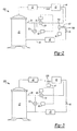
- Figure 1 is a schematic view of a refrigerant system incorporating the instant invention.
- Figure 1A is a cross-sectional view of a scroll compressor.
- Figure 2 shows a second embodiment
- Figure 3 shows yet another embodiment.
- Figure 1 shows a refrigerant circuit 20 incorporating scroll compressor 22.
- the compressor 22 includes an orbiting scroll 23 and a non-orbiting scroll 25.
- the two scroll members define compression chambers 24.
- An economizer injection line 26 communicates with two injection ports 28 for injecting an economized fluid back into the compression chambers 24 at a point intermediate the suction and discharge pressure. While the present invention is specifically disclosed in a scroll compressor, the invention is also applicable to other types of compressors. In particular, screw compressors will also benefit from this invention.
- a discharge line 30 from the compressor leads to a condenser 32.
- a condenser outlet 34 leads to an economizer heat exchanger 40.
- a tap line 36 taps off a portion of the outlet line 34 and passes through an expansion valve 38. When the two fluid flows in the line 34 and 36 pass through the heat exchanger 40, heat is taken away from the fluid in the line 34 by the fluid in the line 36.
- the main flow line 34 continues to the outlet 44 of the economizer heat exchanger 40, and eventually to a main expansion valve 46. From the expansion valve 46, the refrigerant passes through the evaporator 48. From evaporator 48, refrigerant returns through a line 49 to a suction port 51 in the compressor 22.
- the tap line 36 continues to a second outlet 26 of the economizer heat exchanger 40 and eventually to compressor 22 where the refrigerant enters into compression chamber 24 through injection ports 28.
- optional line 52 includes a selectively opened valve 53 to connect the suction line 49 to the economizer line 26.
- valve 53 When the valve 53 is opened, an economizer valve 54 is typically closed.
- refrigerant moves through the ports 28, into the line 52, and back to the suction 49.
- This control is affected by a control 60 when a reduced capacity is desired. Again, control 60 will open the valve 54 and close the valve 53 when economized operation is desired.
- the valve 54 is illustrated as being located on line 26, it is to be understood that the valve 54 can also be located on line 36 instead.
- the circuit as disclosed to this point is generally as known.
- the present invention is directed to the inclusion of a tap 56 to tap liquid from the condenser 32.
- a valve 58 and expansion valve 57 is mounted on line 56 and controls the flow of the liquid to the economizer line 26.
- liquid By including liquid into the line 26, liquid is injected into the compression chambers 24 at an intermediate pressure position. Since the economizer ports 28 are used to inject the liquid, in addition to economizer vapor, no additional flow structure is necessary at the compressor.
- the present invention thus achieves the injection of liquid into the intermediate compression chambers, and the resulting reduction in discharge temperature without the necessity of providing additional flow connections, etc., at the compressor.
- the valve 58 is controlled by control 60 and may be opened such that it injects liquid in conjunction with the economizer valve 54 being open, or in conjunction with the unloader valve 53 being open. Further, the valve 58 can also be opened when both valves 53 and 54 are closed.
- control 60 will be programmed to determine which types of operational states would make the injection of liquid beneficial into the compression chambers 24.
- valves 57 and 58 are separate components, it is to be understood that the valves 57 and 58 can be combined into a single component. Valves 36 and 54 can also be combined into a single component. Additionally, the expansion valves 36 and 57 could also be a capillary tube or a fixed orifice.
- second embodiment 120 is similar to the Figure 1 embodiment except the tap 156 is intermediate the outlet 44 of the economizer heat exchanger and the main expansion valve 46. Again, the tap 156 taps liquid that passes through an expansion device 157 and to the shut-off valve 158. The valve 158 is again opened to inject liquid into the line 26, and eventually into the economizer injection ports 28.
- the operation and control of this embodiment is similar to the Figure 1 embodiment.
- FIG. 3 shows yet another embodiment 220 wherein the economizer expansion valve 238 is an electronic expansion valve.
- a valve can be controlled by the control 60 to over flood the economizer circuit so that a controlled amount of liquid refrigerant is returned through the economizer return line 26 whenever economized operation is occurring. This eliminates the need for any separate liquid injection line.
- the present invention thus achieves the injection of a liquid refrigerant into the compression chambers at an intermediate pressure in an economized system, and without additional flow connections to the compressor 22.
Landscapes
- Engineering & Computer Science (AREA)
- Mechanical Engineering (AREA)
- General Engineering & Computer Science (AREA)
- Physics & Mathematics (AREA)
- Thermal Sciences (AREA)
- Rotary Pumps (AREA)
- Applications Or Details Of Rotary Compressors (AREA)
Claims (8)
- Cycle de fluide réfrigérant (20) comprenant :un compresseur (22) ayant une conduite d'aspiration (49), une conduite de décharge (30) et des chambres de compression (24) de pression intermédiaire au niveau d'une aspiration et d'une décharge intermédiaire de pression ;un condenseur (32) communiquant avec ladite conduite de décharge (30) dudit compresseur (22) ; etun échangeur de chaleur économiseur (40) et un robinet économiseur (36) captant le fluide de l'économiseur d'une conduite de sortie (34) dudit condenseur (32), ledit robinet (36) passant par une soupape d'expansion (38) d'économiseur en amont dudit échangeur de chaleur économiseur (40) de sorte que la chaleur est échangée entre une conduite de sortie principale (34) dudit condenseur (32) et ledit robinet (36) d'économiseur dans ledit échangeur de chaleur économiseur (40) ;ladite conduite de sortie principale (34) passant par un dispositif d'expansion principal (46) et ensuite dans un évaporateur (48) ;ledit fluide de l'économiseur capté passant par une soupape d'économiseur (54) dans une conduite de retour d'économiseur (26), caractérisé en ce que ledit fluide de l'économiseur capté passe par des orifices d'injection (28) d'économiseur pour ramener ledit fluide de l'économiseur auxdites chambres de compression (24) de pression intermédiaire, et en ce que le cycle de fluide réfrigérant (20) comprend en outre une conduite de robinet de liquide (56) pour capter le fluide réfrigérant liquide et l'injecter dans lesdites chambres de compression (24) de pression intermédiaire par lesdits orifices d'injection d'économiseur (28).
- Cycle de fluide réfrigérant (20) selon la revendication 1, dans lequel ledit compresseur (22) est un compresseur à spirale, et on trouve une paire d'orifices d'injection (28) d'économiseur espacés pour communiquer avec lesdites chambres de compression (24) de pression intermédiaire.
- Cycle de fluide réfrigérant (20) selon la revendication 1, dans lequel on trouve une soupape de marche à vide (53) montée sur une conduite (52) raccordant ladite conduite de retour d'économiseur (26) et ladite conduite d'aspiration (49), avec une commande (60) ouvrant sélectivement ladite soupape de marche à vide (53).
- Cycle de fluide réfrigérant (20) selon la revendication 1, dans lequel une soupape d'injection de liquide (58) séparée est comprise dans une conduite raccordant ladite conduite de robinet (96) à ladite conduite de retour d'économiseur (26), ladite soupape d'injection de liquide (58) étant contrôlée de sorte qu'elle peut s'ouvrir lorsque ladite soupape de marche à vide (53) est également ouverte.
- Cycle de fluide réfrigérant (20) selon la revendication 4, dans lequel ladite soupape d'économiseur (54) et ladite soupape d'injection de liquide (58) peuvent être ouvertes toutes les deux en même temps.
- Cycle de fluide réfrigérant (20) selon la revendication 1, dans lequel ladite conduite de robinet de liquide (56) est captée à partir d'un emplacement situé entre ledit robinet économiseur (36) et ladite conduite de sortie de condenseur (34).
- Cycle de fluide réfrigérant (20) selon la revendication 1, dans lequel ladite conduite de robinet de liquide (56) est sur ladite conduite de sortie principale (34) et entre ledit échangeur de chaleur d'économiseur (40) et ledit dispositif d'expansion principal (46).
- Cycle de fluide réfrigérant (20) selon la revendication 1, dans lequel ladite conduite de robinet de liquide (56) est proposée par ledit robinet économiseur (36) et en contrôlant ladite soupape d'expansion d'économiseur (38) pour injecter du liquide supplémentaire dans ladite conduite de retour d'économiseur (26).
Applications Claiming Priority (3)
| Application Number | Priority Date | Filing Date | Title |
|---|---|---|---|
| US10/115,622 US6571576B1 (en) | 2002-04-04 | 2002-04-04 | Injection of liquid and vapor refrigerant through economizer ports |
| US115622 | 2002-04-04 | ||
| PCT/US2003/008349 WO2003085335A1 (fr) | 2002-04-04 | 2003-03-19 | Injection d'un fluide refrigerant liquide ou en phase vapeur par l'intermediaire d'orifices economiseurs |
Publications (2)
| Publication Number | Publication Date |
|---|---|
| EP1492986A1 EP1492986A1 (fr) | 2005-01-05 |
| EP1492986B1 true EP1492986B1 (fr) | 2007-11-14 |
Family
ID=22362495
Family Applications (1)
| Application Number | Title | Priority Date | Filing Date |
|---|---|---|---|
| EP03714237A Expired - Lifetime EP1492986B1 (fr) | 2002-04-04 | 2003-03-19 | Injection d'un fluide refrigerant liquide ou en phase vapeur par l'intermediaire d'orifices economiseurs |
Country Status (6)
| Country | Link |
|---|---|
| US (1) | US6571576B1 (fr) |
| EP (1) | EP1492986B1 (fr) |
| JP (1) | JP4111921B2 (fr) |
| CN (1) | CN100338408C (fr) |
| DE (1) | DE60317491T2 (fr) |
| WO (1) | WO2003085335A1 (fr) |
Cited By (5)
| Publication number | Priority date | Publication date | Assignee | Title |
|---|---|---|---|---|
| US7647790B2 (en) | 2006-10-02 | 2010-01-19 | Emerson Climate Technologies, Inc. | Injection system and method for refrigeration system compressor |
| US8181478B2 (en) | 2006-10-02 | 2012-05-22 | Emerson Climate Technologies, Inc. | Refrigeration system |
| US8539785B2 (en) | 2009-02-18 | 2013-09-24 | Emerson Climate Technologies, Inc. | Condensing unit having fluid injection |
| US8769982B2 (en) | 2006-10-02 | 2014-07-08 | Emerson Climate Technologies, Inc. | Injection system and method for refrigeration system compressor |
| CN110925940A (zh) * | 2019-11-08 | 2020-03-27 | 珠海格力电器股份有限公司 | 一种双级压缩补气装置、空调系统及补气控制方法 |
Families Citing this family (49)
| Publication number | Priority date | Publication date | Assignee | Title |
|---|---|---|---|---|
| CN1764810A (zh) * | 2003-02-28 | 2006-04-26 | Vai控股公司 | 具有集成旁通系统的制冷系统 |
| US6955059B2 (en) * | 2003-03-14 | 2005-10-18 | Carrier Corporation | Vapor compression system |
| DK1498667T3 (da) * | 2003-07-18 | 2010-08-16 | Star Refrigeration | Forbedret transkritisk kølingscyklus |
| JP4140488B2 (ja) * | 2003-09-09 | 2008-08-27 | ダイキン工業株式会社 | スクリュー圧縮機および冷凍装置 |
| US6925823B2 (en) * | 2003-10-28 | 2005-08-09 | Carrier Corporation | Refrigerant cycle with operating range extension |
| US6883341B1 (en) * | 2003-11-10 | 2005-04-26 | Carrier Corporation | Compressor with unloader valve between economizer line and evaporator inlet |
| JP4403300B2 (ja) * | 2004-03-30 | 2010-01-27 | 日立アプライアンス株式会社 | 冷凍装置 |
| US7997091B2 (en) * | 2004-04-22 | 2011-08-16 | Carrier Corporation | Control scheme for multiple operating parameters in economized refrigerant system |
| JP2008511097A (ja) | 2004-05-14 | 2008-04-10 | オールソップ インコーポレイテッド | 太陽エネルギを用いたオフセット型屋外照明装置 |
| US9545300B2 (en) | 2004-12-22 | 2017-01-17 | W. L. Gore & Associates, Inc. | Filament-wound implantable devices |
| US7089848B2 (en) * | 2004-12-22 | 2006-08-15 | Numatics, Incorporated | Non-rotating double acting piston and cylinder assembly |
| CN1865812A (zh) * | 2005-05-19 | 2006-11-22 | 量子能技术股份有限公司 | 热泵系统与加热流体的方法 |
| WO2006130137A2 (fr) | 2005-05-31 | 2006-12-07 | Carrier Corporation | Limitation dans une ligne d'injection de vapeur |
| US7204099B2 (en) * | 2005-06-13 | 2007-04-17 | Carrier Corporation | Refrigerant system with vapor injection and liquid injection through separate passages |
| US7854136B2 (en) * | 2005-08-09 | 2010-12-21 | Carrier Corporation | Automated drive for fan and refrigerant system |
| US8037710B2 (en) * | 2005-08-22 | 2011-10-18 | Emerson Climate Technologies, Inc. | Compressor with vapor injection system |
| CA2626331A1 (fr) * | 2005-10-18 | 2007-04-26 | Carrier Corporation | Systeme de compression de vapeur refrigerante dote d'un cycle economiseur permettant de chauffer de l'eau |
| CN101336357A (zh) * | 2006-01-27 | 2008-12-31 | 开利公司 | 进入蒸发器入口的制冷剂系统缷载旁路 |
| US20070251256A1 (en) * | 2006-03-20 | 2007-11-01 | Pham Hung M | Flash tank design and control for heat pumps |
| EP2064496B1 (fr) * | 2006-09-18 | 2018-04-25 | Carrier Corporation | Système réfrigérant avec dérivation de dispositif d'expansion |
| WO2008054380A2 (fr) * | 2006-10-27 | 2008-05-08 | Carrier Corporation | Cycle frigorifique économisé au moyen d'un détendeur |
| US7674098B2 (en) * | 2006-11-07 | 2010-03-09 | Scroll Technologies | Scroll compressor with vapor injection and unloader port |
| WO2008094157A1 (fr) * | 2007-02-02 | 2008-08-07 | Carrier Corporation | Système réfrigérant amélioré |
| US20100024467A1 (en) * | 2007-02-09 | 2010-02-04 | Hajime Sato | Scroll compressor and air conditioner |
| EP2153139A4 (fr) * | 2007-05-23 | 2012-10-10 | Carrier Corp | Injection de réfrigérant au-dessus du point critique dans un système de réfrigérant transcritique |
| US7997092B2 (en) * | 2007-09-26 | 2011-08-16 | Carrier Corporation | Refrigerant vapor compression system operating at or near zero load |
| WO2009050178A2 (fr) * | 2007-10-17 | 2009-04-23 | Shell Internationale Research Maatschappij B.V. | Procédés et appareils de refroidissement et/ou de liquéfaction d'un flux d'hydrocarbures |
| US7975506B2 (en) * | 2008-02-20 | 2011-07-12 | Trane International, Inc. | Coaxial economizer assembly and method |
| US9353765B2 (en) | 2008-02-20 | 2016-05-31 | Trane International Inc. | Centrifugal compressor assembly and method |
| US7856834B2 (en) | 2008-02-20 | 2010-12-28 | Trane International Inc. | Centrifugal compressor assembly and method |
| US8037713B2 (en) | 2008-02-20 | 2011-10-18 | Trane International, Inc. | Centrifugal compressor assembly and method |
| CA2671109C (fr) * | 2008-07-08 | 2012-10-23 | Tecumseh Products Company | Compresseur a spirale a injection de liquide ou de vapeur |
| WO2010036614A2 (fr) * | 2008-09-26 | 2010-04-01 | Carrier Corporation | Commande de décharge de compresseur sur un système de réfrigération de transport |
| KR101280381B1 (ko) * | 2009-11-18 | 2013-07-01 | 엘지전자 주식회사 | 히트 펌프 |
| WO2011075373A2 (fr) | 2009-12-18 | 2011-06-23 | Carrier Corporation | Système de réfrigération de transport et procédés associés adaptés à des conditions dynamiques |
| CN101922823A (zh) * | 2010-09-02 | 2010-12-22 | 广州德能热源设备有限公司 | 二次喷气高效超低温热泵机组 |
| US9383127B2 (en) * | 2010-10-22 | 2016-07-05 | Tai-Her Yang | Temperature regulation system with active jetting type refrigerant supply and regulation |
| KR101252173B1 (ko) * | 2010-11-23 | 2013-04-05 | 엘지전자 주식회사 | 히트 펌프 및 그 제어방법 |
| EP2920469A2 (fr) * | 2012-09-27 | 2015-09-23 | Vilter Manufacturing Llc | Appareil et procédé pour améliorer le rendement de compresseur |
| US9599353B2 (en) * | 2013-07-26 | 2017-03-21 | Whirlpool Corporation | Split air conditioning system with a single outdoor unit |
| CN103557646B (zh) * | 2013-09-30 | 2015-11-18 | 广东美芝制冷设备有限公司 | 制冷系统和制热系统 |
| ITVI20130257A1 (it) * | 2013-10-18 | 2015-04-19 | Carel Ind Spa | Metodo di azionamento di una macchina frigorifera dotata di apparato economizzatore |
| KR102240070B1 (ko) * | 2014-03-20 | 2021-04-13 | 엘지전자 주식회사 | 공기조화기 및 그 제어방법 |
| US9850903B2 (en) * | 2014-12-09 | 2017-12-26 | Emerson Climate Technologies, Inc. | Capacity modulated scroll compressor |
| JP6414791B2 (ja) * | 2017-06-29 | 2018-10-31 | パナソニックIpマネジメント株式会社 | 冷凍機 |
| JP6735929B2 (ja) * | 2017-10-06 | 2020-08-05 | 三菱電機株式会社 | 冷凍サイクル装置 |
| US10895259B2 (en) | 2018-04-20 | 2021-01-19 | Trane International Inc. | Screw compressor having synchronized economizer ports |
| US12560355B2 (en) | 2021-07-28 | 2026-02-24 | Carrier Corporation | Duct mounted filtering apparatus |
| US12398926B2 (en) | 2021-08-04 | 2025-08-26 | Carrier Corporation | Economizer injection in a reciprocating compressor |
Family Cites Families (8)
| Publication number | Priority date | Publication date | Assignee | Title |
|---|---|---|---|---|
| EP0326189B1 (fr) * | 1985-08-10 | 1991-12-11 | Sanden Corporation | Compresseur à volutes imbriquées avec mécanisme de réglage du déplacement |
| US5095712A (en) * | 1991-05-03 | 1992-03-17 | Carrier Corporation | Economizer control with variable capacity |
| US6032472A (en) * | 1995-12-06 | 2000-03-07 | Carrier Corporation | Motor cooling in a refrigeration system |
| US6041605A (en) * | 1998-05-15 | 2000-03-28 | Carrier Corporation | Compressor protection |
| US5996364A (en) | 1998-07-13 | 1999-12-07 | Carrier Corporation | Scroll compressor with unloader valve between economizer and suction |
| US6324858B1 (en) * | 1998-11-27 | 2001-12-04 | Carrier Corporation | Motor temperature control |
| US6428284B1 (en) * | 2000-03-16 | 2002-08-06 | Mobile Climate Control Inc. | Rotary vane compressor with economizer port for capacity control |
| US6318100B1 (en) * | 2000-04-14 | 2001-11-20 | Carrier Corporation | Integrated electronic refrigerant management system |
-
2002
- 2002-04-04 US US10/115,622 patent/US6571576B1/en not_active Expired - Lifetime
-
2003
- 2003-03-19 JP JP2003582481A patent/JP4111921B2/ja not_active Expired - Fee Related
- 2003-03-19 DE DE60317491T patent/DE60317491T2/de not_active Expired - Lifetime
- 2003-03-19 EP EP03714237A patent/EP1492986B1/fr not_active Expired - Lifetime
- 2003-03-19 WO PCT/US2003/008349 patent/WO2003085335A1/fr not_active Ceased
- 2003-03-19 CN CNB038077817A patent/CN100338408C/zh not_active Expired - Fee Related
Cited By (6)
| Publication number | Priority date | Publication date | Assignee | Title |
|---|---|---|---|---|
| US7647790B2 (en) | 2006-10-02 | 2010-01-19 | Emerson Climate Technologies, Inc. | Injection system and method for refrigeration system compressor |
| US8181478B2 (en) | 2006-10-02 | 2012-05-22 | Emerson Climate Technologies, Inc. | Refrigeration system |
| US8769982B2 (en) | 2006-10-02 | 2014-07-08 | Emerson Climate Technologies, Inc. | Injection system and method for refrigeration system compressor |
| US8539785B2 (en) | 2009-02-18 | 2013-09-24 | Emerson Climate Technologies, Inc. | Condensing unit having fluid injection |
| CN110925940A (zh) * | 2019-11-08 | 2020-03-27 | 珠海格力电器股份有限公司 | 一种双级压缩补气装置、空调系统及补气控制方法 |
| CN110925940B (zh) * | 2019-11-08 | 2020-11-13 | 珠海格力电器股份有限公司 | 一种双级压缩补气空调系统的补气控制方法 |
Also Published As
| Publication number | Publication date |
|---|---|
| DE60317491D1 (de) | 2007-12-27 |
| JP2005521854A (ja) | 2005-07-21 |
| CN1646866A (zh) | 2005-07-27 |
| US6571576B1 (en) | 2003-06-03 |
| HK1081259A1 (zh) | 2006-05-12 |
| JP4111921B2 (ja) | 2008-07-02 |
| WO2003085335A1 (fr) | 2003-10-16 |
| DE60317491T2 (de) | 2008-09-18 |
| EP1492986A1 (fr) | 2005-01-05 |
| CN100338408C (zh) | 2007-09-19 |
Similar Documents
| Publication | Publication Date | Title |
|---|---|---|
| EP1492986B1 (fr) | Injection d'un fluide refrigerant liquide ou en phase vapeur par l'intermediaire d'orifices economiseurs | |
| US7100386B2 (en) | Economizer/by-pass port inserts to control port size | |
| KR100309975B1 (ko) | 용량제어장치 | |
| US5996364A (en) | Scroll compressor with unloader valve between economizer and suction | |
| US6694750B1 (en) | Refrigeration system employing multiple economizer circuits | |
| US6385981B1 (en) | Capacity control of refrigeration systems | |
| US6883341B1 (en) | Compressor with unloader valve between economizer line and evaporator inlet | |
| US20080256961A1 (en) | Economized Refrigerant System with Vapor Injection at Low Pressure | |
| EP1139039B1 (fr) | Amélioration d'un circuit d'économiseur | |
| US20080078204A1 (en) | Refrigeration system | |
| KR20080041565A (ko) | 증기 인젝션 및 언로더 포트를 포함하는 스크롤 압축기 | |
| US7251947B2 (en) | Refrigerant system with suction line restrictor for capacity correction | |
| US8661846B2 (en) | Restriction in vapor injection line | |
| HK1081259B (en) | Refrigerant cycle | |
| HK1133066B (en) | Economized refrigerant system with vapor injection at low pressure | |
| HK1133065B (en) | Refrigerant system and method of operating the refrigant system | |
| HK1124376B (en) | Refrigerant system with suction line restrictor for capacity correction | |
| HK1128045A (en) | Refrigerant system unloading by-pass into evaporator inlet | |
| HK1121522A1 (en) | Refrigerant system with vapor injection and liquid injection through separate passages |
Legal Events
| Date | Code | Title | Description |
|---|---|---|---|
| PUAI | Public reference made under article 153(3) epc to a published international application that has entered the european phase |
Free format text: ORIGINAL CODE: 0009012 |
|
| 17P | Request for examination filed |
Effective date: 20041102 |
|
| AK | Designated contracting states |
Kind code of ref document: A1 Designated state(s): AT BE BG CH CY CZ DE DK EE ES FI FR GB GR HU IE IT LI LU MC NL PT RO SE SI SK TR |
|
| RAP1 | Party data changed (applicant data changed or rights of an application transferred) |
Owner name: CARRIER CORPORATION |
|
| GRAP | Despatch of communication of intention to grant a patent |
Free format text: ORIGINAL CODE: EPIDOSNIGR1 |
|
| GRAS | Grant fee paid |
Free format text: ORIGINAL CODE: EPIDOSNIGR3 |
|
| GRAA | (expected) grant |
Free format text: ORIGINAL CODE: 0009210 |
|
| AK | Designated contracting states |
Kind code of ref document: B1 Designated state(s): BE DE FR GB NL |
|
| REG | Reference to a national code |
Ref country code: GB Ref legal event code: FG4D |
|
| REF | Corresponds to: |
Ref document number: 60317491 Country of ref document: DE Date of ref document: 20071227 Kind code of ref document: P |
|
| PGFP | Annual fee paid to national office [announced via postgrant information from national office to epo] |
Ref country code: NL Payment date: 20080331 Year of fee payment: 6 |
|
| ET | Fr: translation filed | ||
| PLBE | No opposition filed within time limit |
Free format text: ORIGINAL CODE: 0009261 |
|
| STAA | Information on the status of an ep patent application or granted ep patent |
Free format text: STATUS: NO OPPOSITION FILED WITHIN TIME LIMIT |
|
| PGFP | Annual fee paid to national office [announced via postgrant information from national office to epo] |
Ref country code: BE Payment date: 20080411 Year of fee payment: 6 |
|
| 26N | No opposition filed |
Effective date: 20080815 |
|
| BERE | Be: lapsed |
Owner name: CARRIER CORP. Effective date: 20090331 |
|
| NLV4 | Nl: lapsed or anulled due to non-payment of the annual fee |
Effective date: 20091001 |
|
| PG25 | Lapsed in a contracting state [announced via postgrant information from national office to epo] |
Ref country code: NL Free format text: LAPSE BECAUSE OF NON-PAYMENT OF DUE FEES Effective date: 20091001 Ref country code: BE Free format text: LAPSE BECAUSE OF NON-PAYMENT OF DUE FEES Effective date: 20090331 |
|
| REG | Reference to a national code |
Ref country code: FR Ref legal event code: PLFP Year of fee payment: 14 |
|
| REG | Reference to a national code |
Ref country code: FR Ref legal event code: PLFP Year of fee payment: 15 |
|
| REG | Reference to a national code |
Ref country code: DE Ref legal event code: R082 Ref document number: 60317491 Country of ref document: DE Representative=s name: SCHMITT-NILSON SCHRAUD WAIBEL WOHLFROM PATENTA, DE |
|
| REG | Reference to a national code |
Ref country code: FR Ref legal event code: PLFP Year of fee payment: 16 |
|
| PGFP | Annual fee paid to national office [announced via postgrant information from national office to epo] |
Ref country code: GB Payment date: 20180226 Year of fee payment: 16 Ref country code: DE Payment date: 20180219 Year of fee payment: 16 |
|
| PGFP | Annual fee paid to national office [announced via postgrant information from national office to epo] |
Ref country code: FR Payment date: 20180220 Year of fee payment: 16 |
|
| REG | Reference to a national code |
Ref country code: DE Ref legal event code: R119 Ref document number: 60317491 Country of ref document: DE |
|
| GBPC | Gb: european patent ceased through non-payment of renewal fee |
Effective date: 20190319 |
|
| PG25 | Lapsed in a contracting state [announced via postgrant information from national office to epo] |
Ref country code: DE Free format text: LAPSE BECAUSE OF NON-PAYMENT OF DUE FEES Effective date: 20191001 Ref country code: GB Free format text: LAPSE BECAUSE OF NON-PAYMENT OF DUE FEES Effective date: 20190319 |
|
| PG25 | Lapsed in a contracting state [announced via postgrant information from national office to epo] |
Ref country code: FR Free format text: LAPSE BECAUSE OF NON-PAYMENT OF DUE FEES Effective date: 20190331 |