EP1493065B2 - Dispositif et procede pour simuler des processus de production - Google Patents
Dispositif et procede pour simuler des processus de production Download PDFInfo
- Publication number
- EP1493065B2 EP1493065B2 EP03722456A EP03722456A EP1493065B2 EP 1493065 B2 EP1493065 B2 EP 1493065B2 EP 03722456 A EP03722456 A EP 03722456A EP 03722456 A EP03722456 A EP 03722456A EP 1493065 B2 EP1493065 B2 EP 1493065B2
- Authority
- EP
- European Patent Office
- Prior art keywords
- production
- simulation
- liquid
- immersing
- emerging
- Prior art date
- Legal status (The legal status is an assumption and is not a legal conclusion. Google has not performed a legal analysis and makes no representation as to the accuracy of the status listed.)
- Expired - Lifetime
Links
- 238000000034 method Methods 0.000 title claims abstract description 110
- 238000004519 manufacturing process Methods 0.000 title claims abstract description 33
- 239000007788 liquid Substances 0.000 claims abstract description 54
- 238000007654 immersion Methods 0.000 claims abstract description 14
- 238000012545 processing Methods 0.000 claims description 69
- 238000004088 simulation Methods 0.000 claims description 44
- 238000000576 coating method Methods 0.000 claims description 22
- 239000011248 coating agent Substances 0.000 claims description 18
- 238000004140 cleaning Methods 0.000 claims description 12
- 238000005507 spraying Methods 0.000 claims description 6
- 238000001035 drying Methods 0.000 claims description 5
- 238000003618 dip coating Methods 0.000 claims description 2
- 229920001187 thermosetting polymer Polymers 0.000 claims 1
- 238000002360 preparation method Methods 0.000 abstract description 4
- 238000006073 displacement reaction Methods 0.000 abstract 1
- 238000004381 surface treatment Methods 0.000 description 18
- 239000003973 paint Substances 0.000 description 8
- 238000007591 painting process Methods 0.000 description 6
- 238000005554 pickling Methods 0.000 description 6
- 238000010422 painting Methods 0.000 description 5
- 101100493712 Caenorhabditis elegans bath-42 gene Proteins 0.000 description 4
- 238000000151 deposition Methods 0.000 description 4
- 238000012360 testing method Methods 0.000 description 4
- 101100493711 Caenorhabditis elegans bath-41 gene Proteins 0.000 description 3
- 230000000694 effects Effects 0.000 description 3
- 239000004922 lacquer Substances 0.000 description 3
- 238000013022 venting Methods 0.000 description 3
- 238000004364 calculation method Methods 0.000 description 2
- 238000004590 computer program Methods 0.000 description 2
- 238000011960 computer-aided design Methods 0.000 description 2
- 238000013461 design Methods 0.000 description 2
- 238000007598 dipping method Methods 0.000 description 2
- 239000012530 fluid Substances 0.000 description 2
- 238000005246 galvanizing Methods 0.000 description 2
- 239000002184 metal Substances 0.000 description 2
- 239000007921 spray Substances 0.000 description 2
- 238000003860 storage Methods 0.000 description 2
- 230000002730 additional effect Effects 0.000 description 1
- 238000004458 analytical method Methods 0.000 description 1
- 238000013459 approach Methods 0.000 description 1
- 244000052616 bacterial pathogen Species 0.000 description 1
- 238000003287 bathing Methods 0.000 description 1
- 210000000746 body region Anatomy 0.000 description 1
- 230000037237 body shape Effects 0.000 description 1
- 230000036760 body temperature Effects 0.000 description 1
- 238000001816 cooling Methods 0.000 description 1
- 230000008021 deposition Effects 0.000 description 1
- 238000011161 development Methods 0.000 description 1
- 230000018109 developmental process Effects 0.000 description 1
- 230000005684 electric field Effects 0.000 description 1
- 238000004070 electrodeposition Methods 0.000 description 1
- 238000002474 experimental method Methods 0.000 description 1
- 238000011049 filling Methods 0.000 description 1
- 238000010438 heat treatment Methods 0.000 description 1
- 238000003780 insertion Methods 0.000 description 1
- 230000037431 insertion Effects 0.000 description 1
- 238000013508 migration Methods 0.000 description 1
- 230000005012 migration Effects 0.000 description 1
- 230000035515 penetration Effects 0.000 description 1
- 238000003672 processing method Methods 0.000 description 1
- 238000000746 purification Methods 0.000 description 1
- 230000005855 radiation Effects 0.000 description 1
- 238000009423 ventilation Methods 0.000 description 1
- XLYOFNOQVPJJNP-UHFFFAOYSA-N water Substances O XLYOFNOQVPJJNP-UHFFFAOYSA-N 0.000 description 1
Images


Classifications
-
- G—PHYSICS
- G05—CONTROLLING; REGULATING
- G05B—CONTROL OR REGULATING SYSTEMS IN GENERAL; FUNCTIONAL ELEMENTS OF SUCH SYSTEMS; MONITORING OR TESTING ARRANGEMENTS FOR SUCH SYSTEMS OR ELEMENTS
- G05B17/00—Systems involving the use of models or simulators of said systems
- G05B17/02—Systems involving the use of models or simulators of said systems electric
Definitions
- the invention relates to an apparatus and a method for simulating production and / or production preparation and / or production after-treatment processes, in particular surface treatment methods.
- the body surfaces are treated by methods that generally include a variety of different steps.
- one or more surface pre- and / or surface post-treatment steps may also be carried out before or after the actual surface treatment steps.
- the body is cleaned thoroughly, if necessary in several stages. For example, the body is first pre-cleaned, then degreased, rinsed, phosphated, etc. appropriate spraying and / or Tauchentfettungsvons steps are performed or the body can be immersed in one or more cleaning liquid baths.
- the body is e.g. immersed in a (further) bath, for example a dye bath, where e.g. by means of a cathodic deposition method, e.g. a cathodic dip coating method, a (first) coating or a (first) coating is applied to the body, e.g. a base coat layer.
- a cathodic deposition method e.g. a cathodic dip coating method
- a (first) coating or a (first) coating is applied to the body, e.g. a base coat layer.
- the coating process it is possible to previously use e.g. one or more pickling process steps are performed; e.g.
- the body can be immersed in a pickling, especially a galvanizing pickling baths.
- the applied coating or paint layer can be cured or dried in an oven, and then the body can be cooled again.
- the applied coating or coating is then e.g. Hardened or dried in another oven, and then cooled the body again, etc.
- the body panels have i.A. several open cavities. When immersing the body in the corresponding liquid bath, it may come in these cavities to the inclusion of air bubbles; these prevent the corresponding cavity from being completely wetted with liquid.
- the trapped air bubbles can result in relatively high buoyancy forces in a body immersed in a liquid bath; the bodywork sheet is thereby mechanically exposed to high stress. This may be so large that the shell structure of the body is damaged, e.g. is dented.
- liquid residues may remain which may impair subsequent process steps.
- the shape of the bodywork must then be subsequently changed (e.g., by providing additional vent holes for venting air upon immersion, and / or additional drainage holes for venting fluid during dewatering).
- the US 5 527 477 shows a robot with spray gun, in which a simulation method is used to control the coating.
- the invention has for its object to provide a novel device and a novel method for simulating production and / or production preparation and / or production aftertreatment processes, in particular surface treatment methods.
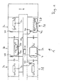
- FIG. 1 is a schematic representation of a portion of a production line 1 shown, in which in a plurality of successive stages 3a, 3b, 3c, 3c, 3d, 3e, 3f, a surface treatment of vehicle bodies 2a, 2b, 2c, 2d is made.
- the vehicle bodies 2a, 2b, 2c, 2d all have substantially the same shape, and are illustrated by corresponding arrows, e.g. with the help of a conveyor belt fully automatically first to the first processing stage 3a, from there to the second processing stage 3b, the third processing stage 3c, and then to the other processing stages 3d, 3e, 3f promoted, etc.
- the vehicle bodies may also have different shapes (eg, a body of a convertible, a caravan, etc., can be successively transported through the various processing stages).
- processing stages - theharikatosserien 2a, 2b, 2c, 2d are thoroughly cleaned.
- the respective vehicle body 2a, 2b, 2c, 2d in particular the body interior initially pre-cleaned in the processing stage 3a, and then in the processing stages 3b - and possibly in other processing stages not shown here - spray degreased, Tauchentfettet, rinsed, phosphated , passivated, etc.
- vehicle bodies 2a, 2b, 2c, 2d After the vehicle bodies 2a, 2b, 2c, 2d have been cleaned, they are supplied from the corresponding cleaning processing stages 3a, 3b from another processing stage 3c where the vehicle bodies 2a, 2b, 2c, 2d - e.g. by means of a robot 21 - tilted back and forth, e.g. in order to remove as far as possible the cleaning liquid which may still be present on the bodywork surface or in body cavities.
- the corresponding vehicle body 2a, 2b, 2c, 2d is moved by means of a robot 22, e.g. into a (paint) bath or a (paint) basin 42, and then recessed, in particular into a bath, in which by means of a cathodic deposition method (eg an electro deposition coating method) a (first) coating or .
- a (first) coating is applied to the body, eg a base coat layer or any other coating.
- the cathodic deposition method used here may be e.g. a cathodic dip painting process.
- the vehicle cabinets 2a, 2b, 2c, 2d can, for example, in further processing stages (not shown here) be used. corresponding spraying and / or immersion rinsing processes, etc., and / or one or more pickling process steps may be performed, e.g. by immersing and dipping the vehicle bodies 2a, 2b, 2c, 2d in a pickling, in particular a galvanizing pickling bath.
- any other surface processing methods than those mentioned above, e.g. appropriate paints can be sprayed onto the vehicle body 2a, 2b, 2c, 2d, etc.
- the vehicle bodies 2a, 2b, 2c, 2d are fed to a further processing stage (not shown here) where the vehicle bodies 2a, 2b, 2c, 2d - eg by means of a robot - tossed and turned back and forth, For example, to remove as much as possible excess, existing on the body surface or in body cavities, paint.
- the corresponding vehicle body 2a, 2b, 2c, 2d is fed to another processing stage, not shown here, where the respective vehicle body 2a, 2b, 2c, 2d - e.g. by means of appropriate cooling units - is cooled.
- the corresponding vehicle body 2a, 2b, 2c, 2d may be fed to any further processing stage, e.g. another cleaning and / or surface processing stage 3f, etc.
- an electrostatic painting process for example an electrostatic painting process
- another coating e.g. a (further) lacquer layer, for example a color or topcoat layer applied to the vehicle body 2a, 2b, 2c, 2d.
- paint is sprayed onto the body surface by means of appropriate robots 23, the spraying being assisted by generating corresponding electric fields.
- the (initially still liquid) coating or (lacquer) layer applied in the processing stage 3f is processed in a further processing step with a processing step as described in US Pat FIG. 1 cured furnace 4 shown corresponding oven or dried.
- FIG. 2 is a schematic, simplified for illustrative purposes representation of carried out in the painting stage 3d process steps shown.
- the corresponding vehicle body 2a, 2b, 2c, 2d first, for example, by means of an arm, not shown here, of the robot 22 by 180 ° about a centrally in the longitudinal direction through the corresponding vehicle body 2a, 2b, 2c, 2d passing axis of rotation (see. Arrow A) is rotated (so that the body roof then points vertically downwards), and at the same time by means of a forward-down directed movement (see arrow B) with the vehicle body front completely immersed in the bath 42.
- the corresponding vehicle body 2 a, 2 b, 2 c, 2 d is then further moved (arrow C), and then out of the bath 42 again.
- the corresponding vehicle body 2a, 2b, 2c, 2d is again rotated by 180 ° about an axis of rotation passing centrally through the corresponding vehicle body 2a, 2b, 2c, 2d (see arrow D) by means of the robot 22 (so that the body roof then again pointing vertically upwards), and simultaneously moved forwards-upwards (vgL arrow E).
- the arm of the robot 22 (and thus the movement performed by the vehicle body 2a, 2b, 2c, 2d in the above-mentioned insertion and removal operation) is controlled by a control device 11, e.g. a computer 12, on whose memory device 13 a corresponding control software program is stored (computer program product), for example, by the control device 11 corresponding control signals to a control data bus 18, and from there to the robot 22 are output.
- a control device 11 e.g. a computer 12
- a control software program stored (computer program product)
- the speed of entry and exit of the vehicle body 2a, 2b, 2c, 2d into the bath 42 is controlled (in particular the height and, if necessary, the time course of the speed in the case of movements directed to the front or to the front or to the top) B, E), and the height and possibly the time course of the speed during the rotational movements (see arrows A, D), as well as the height and possibly the time course of the speed during the advancing movement in the bath 42 (vgL arrow C) ,
- control device 11 e.g. be controlled by driving the corresponding robot of taking place after the processing stage 3d vehicle body tilting (in particular the height and the time course of - lying on a vertical plane - tilting speed component, and / or the height and the time course of a superimposed - located on a horizontal plane - rotational speed component, and / or the height and the time course of a superimposed feed rate, etc.).
- the control device 11 can furthermore also control one or more of the method steps carried out in the other processing stages 3a, 3b, 3c, 3e, 3f (eg the dwell period of the vehicle bodies 2a, 2b, 2c 2 d in the oven 4 or the duration of the curing or drying period, and / or the heating of active jet surfaces of the furnace 4, and / or the strength of an air flow generated by nozzles 5 a, 5 b, 5 c provided in the furnace 4, and / or or the strength of radiation emitted in the oven 4 provided UV lamps, etc.)
- the method steps carried out in the other processing stages 3a, 3b, 3c, 3e, 3f eg the dwell period of the vehicle bodies 2a, 2b, 2c 2 d in the oven 4 or the duration of the curing or drying period, and / or the heating of active jet surfaces of the furnace 4, and / or the strength of an air flow generated by nozzles 5 a, 5 b, 5 c provided in the furnace 4, and / or or
- control device 11 can for this purpose, for example via the above-mentioned control data bus 18 except with the processing level 3d additionally with the processing stage 3a and / or the processing stage 3b and / or the processing stage 3c and / or the processing stage 3e and / or the processing stage 3f and / or one or more between or before or after these processing stages 3a, 3b, 3c, 3d, 3e, 3f, and correspondingly control the corresponding parameters of the body surface treatment processes taking place there (eg by correspondingly driving robots 20, 21, 23, etc.).
- the corresponding process parameters of the processing stages 3a, 3b, 3c, 3d, 3e, 3f may also be controlled separately by one or more separate control means.
- the trapped air bubbles can result in such high buoyancy forces that the shell structure of the vehicle body 2a, 2b, 2c, 2d is damaged, e.g. is dented.
- a corresponding unfavorable adjustment of the process parameters can result in - even after the e.g. in the processing stage 3c taking place vehicle body tilting or turning operation - remain in sinks of the vehicle body liquid residues that may affect the subsequent process steps.
- Simulation software program performed a simulation of the processes taking place at the corresponding stages.
- This simulation may be subject to its own methodology, the finite element method (FEM or Finite Element Method), or a combination of its own original methodology and FEM methodology.
- the determined process parameters or the determined process parameters representing data are then transferred from the simulation software program to the control software program (alternatively, the function of the simulation and the control software program can be fulfilled, for example, by one and the same software program) that the control device 11 (or the control software program) then in the surface treatment of real existing vehicle bodies 2a, 2b, 2c, 2d the corresponding, in the processing stages 3b, 3d (or additionally in the processing stages 3a, 3c, 3e , 3f) controls processes carried out accordingly.
- a coarse adjustment of the process parameters takes place in the simulation.
- the fine tuning of the process parameters is carried out - following the simulation - by means of a "trial and error” method which corresponds to the conventional "trial and error” method (ie by using vehicle body prototypes at the processing stages 3b, 3d (and, alternatively, correspondingly also at the processing stages 3a, 3c, 3e, 3f) corresponding test series are carried out).
- simulated first with predetermined (for example based on empirical values) process parameters is subjected to a judgment, and - if the result is unsatisfactory - the process parameters and / or the configuration of the vehicle cabinets 2a, 2b, 2c, 2d are changed. Then, a new simulation of the process can be carried out, whereupon again - if the result is unsatisfactory - the process parameters and / or the design of the vehicle bodies 2a, 2b, 2c, 2d can be changed, etc.
- a finite element model 30 of the respective vehicle body 2a, 2b, 2c, 2d is used (preferably one and the same finite element model is used here in the simulation of several, in particular all, of the processes examined).
- a computer network used for calculating or simulating other variables, eg the mechanical load on the vehicle body 2a, 2b, 2c, 2d
- the memory device 13 of the computer 12 can be used, which is read into the memory device 13 of the computer 12.
- the mechanics simulation computing network becomes then adjusted so that - as here - it can be used to simulate the above surface treatment operations.
- the vehicle body surfaces in each case in a plurality of respectively between several, for example three or four reference points spanned, adjacent (eg, flat) reference surfaces divided (finite body surface elements 24, 25, 26 and "cells").
- the simulation software program uses the finite element model 30 to determine areas of the vehicle body 2a, 2b, 2c, 2d in which - when immersed in the bath 41, 42 - air bubbles can be trapped (hereinafter "pockets"). called).
- the identification of the pockets or pockets takes place (in a first variant) purely from the sheet metal geometry, as well as the (current) position or (angular) position of the vehicle body 2a, 2b, 2c, 2d with respect to a reference surface, e.g. a horizontal plane or the surface of the existing in the bathroom 41, 42 liquid.
- the bags or cups are identified by - with respect to the o.g. Reference surface - local maxima or minima present in the sheet metal geometry can be determined.
- a certain number of positions of the vehicle body 2a, 2b, 2c, 2d, which occupies the vehicle body 2a, 2b, 2c, 2d during the replacement process e.g 5 - 500, in particular 10 - 100 different, successive positions.
- a position may be used that occupies the vehicle body 2a, 2b, 2c, 2d immediately after the start of the replacement operation (start position of the vehicle body 2a, 2b, 2c, 2d relative to the liquid surface).
- a certain number of positions of the vehicle body 2a, 2b, 2c, 2d are investigated, which occupies the vehicle body 2a, 2b, 2c, 2d during the immersion process (eg 5 - 500, in particular 10 - 100 different, successive positions).
- the first position e.g. a position which occupies the vehicle body 2a, 2b, 2c, 2d immediately after the start of the dipping operation (start position of the vehicle body 2a, 2b, 2c, 2d relative to the liquid surface) may be used.
- the volume of the respective local maxima or minima or the respective cup or bag are determined (s.u.)
- the simulation as a whole is thus carried out in several successive simulation steps.
- individual, designed for the simulation of a single step program parts of the simulation software program are repeated several times in succession.
- the o.g. Single-step simulation uses vehicle body or sheet geometry neighbor relationship data, which must be set only once - at the beginning of the simulation.
- the location (and possibly additionally the volume) of pockets / cups determined by the simulation software program is determined on the basis of the finite element model 30 on a display device connected to the control device 11, e.g. displayed on a screen, with pockets on the screen e.g. each can be highlighted in different ways in color.
- one or more of the o.g. (in the first variant not considered) effects included in the simulation in contrast, one or more of the o.g. (in the first variant not considered) effects included in the simulation.
- the flow resistances eg the respective drainage opening / vent or the respectively overflowed element edge
- the vehicle body 2a, 2b, 2c , 2d is required in order to get from a certain, respectively considered position to the position subsequently considered when entering or exiting - to an outflow which is smaller than 100% however, the simulation is based on individual, defined time steps).
- the simulation also takes into account the respective amount of deposition of the liquid, in particular on inclined surfaces.
- a model based on the finite element method can be used to describe the body to be calculated - e.g. from crash calculations, or a computer-aided design (CAD) common geometry description.
- FEM finite element method
- CAD computer-aided design
- This network is automatically or semi-automatically classified
- the implementation is done by reading in an ASCII file (that is, there is no tight programming, for example in ANSYS). This will u.a. high flexibility compared to other FEM solutions (reading NASTRAN decks etc.)
- the flat surfaces are e.g. Attributes such as location assigned to the surface in the water bath, and attributes such as e.g. Size, location, etc.
- the pocket or cup volume is determined (if necessary), and then the pocket or cup migration when the angle changes, and then the pockets or cups or the feed surfaces at the end position vehicle body 2a, 2b , 2c, 2d.
- a dripping and / or dripping off of liquid is taken into account.
- the simulation software program (or alternatively the combined simulation / control software program) stored on the storage device 13 comprises a plurality of software modules 33a, 33b, 33c, 33d, 33e, 33f.
- Each software module 33a, 33b, 33c, 33d, 33e, 33f is used to simulate the body surface treatment processes taking place in a specific processing stage 3a, 3b, 3c, 3d, 3e, 3f (eg, the software module 33a is used the simulation of the body surface treatment process taking place in the processing stage 3a, the software module 33b of the simulation of the body surface treatment process taking place in the processing stage 3b, the software module 33c of the simulation of the processing stage 3c takes place on the body surface treatment process, the software module 33d of the simulation of the body surface treatment process taking place in the processing step 3d, etc.).
- Each software module 33a, 33b, 33c, 33d, 33e, 33f is programmed to alternatively load onto the memory device 13 independently of or without the other software modules (n), and / or independently - i. independently of the other software modules - to simulate the body surface treatment process taking place in the respective software module 33a, 33b, 33c, 33d, 33e, 33f associated processing stage 3a, 3b, 3c, 3d, 3e, 3f can be used.
- the body surface treatment processes taking place in the individual processing stages 3a, 3b, 3c, 3d, 3e, 3f are not independent of each other, but may influence one another.
- the body temperature value T K determined in the simulation of the drying or curing process taking place in the processing stage 3 e influences the temperature in the subsequent processing stage 3f takes place coating or painting process. Therefore, according to FIG. 4 the corresponding temperature value T K or a temperature value vector T K ) describing the temperatures of all or selected finite body surface elements 24, 25, 26 are transferred from the software module 33 e to the software module 33 f (and / or alternatively also to further, software modules using the corresponding parameter). The corresponding temperature value T K or the temperature value vector T K is then used by the software module 33 f to carry out the simulation of the coating or painting process taking place in the processing stage 3 f.
- one or more parameters describing the fouling or carry-over e.g. from the corresponding software module associated with the respective processing stage causing the carryover to the corresponding software module simulating the subsequent painting or cleaning process.
- the corresponding parameters are then - possibly together with many other parameters - used by the painting or cleaning process simulation module to simulate the painting or makesptozesses.
- the o.g. Coating process e.g. influence the drying or hardening process taking place in the processing stage 3e.
- parameters describing the location and / or amount of residual liquid left in depressions of the vehicle body 2a, 2b, 2c, 2d may e.g. from the corresponding software module 33d to the corresponding softwate module 33e simulating the subsequent drying or hardening process, and / or the coating thickness as a function of the respective location of the vehicle body, descriptive parameters, etc.
Landscapes
- Physics & Mathematics (AREA)
- General Physics & Mathematics (AREA)
- Engineering & Computer Science (AREA)
- Automation & Control Theory (AREA)
- Application Of Or Painting With Fluid Materials (AREA)
- Multi-Process Working Machines And Systems (AREA)
- External Artificial Organs (AREA)
Claims (14)
- Procédé de simulation de processus de production et/ou de processus préparatoires de production et/ou de processus de post-traitement de production,
caractérisé en ce que le procédé comporte l'étape de :- simulation d'un processus d'immersion et/ou d'émersion d'une carrosserie de véhicule (2a, 2b, 2c, 2d) respectivement dans un ou hors d'un bain de liquides (41, 42) en utilisant un modèle à éléments finis de la carrosserie de véhicule, en détectant lors de la simulation l'emplacement de parties de la carrosserie de véhicule, dans lesquelles de l'air est inclus pendant le processus d'immersion et/ou dans lesquelles des liquides se sont accumulés pendant le processus d'émersion. - Procédé selon la revendication 1, dans lequel le bain de liquides (41) est un bain de nettoyage.
- Procédé selon la revendication 1 ou 2, dans lequel le bain de liquides (42) est un bain de revêtement, notamment un bain de peinture.
- Procédé selon l'une des revendications précédentes, dans lequel au moins un paramètre déterminé lors de la simulation du processus d'immersion ou d'émersion ou de mise en mouvement est utilisé pour simuler un autre processus de production ou processus préparatoire de production ou processus de post-traitement de production.
- Procédé selon la revendication 4, dans lequel l'autre processus de production ou processus préparatoire de production ou processus de post-traitement de production est un processus de séchage ou de durcissement, ou un processus de revêtement, notamment un processus de peinture au trempé cathodique ou un processus de peinture par pulvérisation électrostatique.
- Procédé selon la revendication 4 ou 5, dans lequel l'autre processus de production ou processus préparatoire de production ou processus de post-traitement de production est réalisé dans une station de traitement (3e) qui est localement distante de la station de traitement (3d) où se déroule le processus d'immersion ou d'émersion.
- Procédé selon l'une des revendications 4 à 6, dans lequel la simulation du processus d'immersion ou d'émersion ou de mise en mouvement de la carrosserie de véhicule est effectuée dans un premier module (33d), et la simulation de l'autre processus de production ou processus préparatoire de production ou processus de post-traitement de production est réalisée dans un second module (33e).
- Procédé selon la revendication 7, dans lequel le premier module (33d) peut être également utilisé indépendamment du second module (33e), et/ou le second module (33e) peut être aussi utilisé indépendamment du premier module (33d).
- Procédé selon l'une des revendications précédentes, dans lequel lors de la simulation du processus d'immersion ou d'émersion respectivement dans le ou hors du bain de liquides les vitesses de pénétration et d'écoulement respectivement dans ou hors des parties de la carrosserie de véhicule (2a, 2b, 2c, 2d) sont négligées.
- Procédé selon l'une des revendications 1 à 8, dans lequel lors de la simulation du processus d'immersion ou d'émersion respectivement dans le ou hors du bain de liquides les vitesses de pénétration ou d'écoulement respectivement dans ou hors des parties de la carrosserie de véhicule (2a, 2b, 2c, 2d) sont prises en considération.
- Procédé selon l'une des revendications précédentes, dans lequel lors de la simulation du processus d'immersion ou d'émersion respectivement dans le ou hors du bain de liquides les quantités de liquides s'égouttant dans le bain de liquides et/ou les quantités de liquides gouttant sur le bain de liquides sont négligées.
- Procédé selon l'une des revendications 1 à 10, dans lequel lors de la simulation du processus d'immersion ou d'émersion respectivement dans le ou hors du bain de liquides les quantités de liquides s'égouttant et/ou gouttant sont prises en considération.
- Procédé selon l'une des revendications précédentes, dans lequel la simulation du processus d'immersion ou d'émersion ou de mise en mouvement est sensiblement basée sur des données géométriques définissant la carrosserie de véhicule (2a, 2b, 2c, 2d) et sur la position angulaire de celle-ci par rapport à un plan de référence, notamment la surface du liquide.
- Dispositif (11) de simulation de processus de production et/ou de processus préparatoires de production et/ou de processus de post-traitement de production, lequel est conçu et agencé de sorte à permettre la mise en oeuvre d'un procédé de simulation selon l'une des revendication 1 à 10.
Applications Claiming Priority (3)
| Application Number | Priority Date | Filing Date | Title |
|---|---|---|---|
| DE10217022 | 2002-04-11 | ||
| DE10217022A DE10217022A1 (de) | 2002-04-11 | 2002-04-11 | Vorrichtung und Verfahren zur Simulation von Produktionsprozessen |
| PCT/EP2003/003796 WO2003085464A1 (fr) | 2002-04-11 | 2003-04-11 | Dispositif et procede pour simuler des processus de production |
Publications (3)
| Publication Number | Publication Date |
|---|---|
| EP1493065A1 EP1493065A1 (fr) | 2005-01-05 |
| EP1493065B1 EP1493065B1 (fr) | 2006-07-12 |
| EP1493065B2 true EP1493065B2 (fr) | 2010-06-16 |
Family
ID=28685136
Family Applications (1)
| Application Number | Title | Priority Date | Filing Date |
|---|---|---|---|
| EP03722456A Expired - Lifetime EP1493065B2 (fr) | 2002-04-11 | 2003-04-11 | Dispositif et procede pour simuler des processus de production |
Country Status (5)
| Country | Link |
|---|---|
| EP (1) | EP1493065B2 (fr) |
| AT (1) | ATE333117T1 (fr) |
| AU (1) | AU2003229651A1 (fr) |
| DE (2) | DE10217022A1 (fr) |
| WO (1) | WO2003085464A1 (fr) |
Families Citing this family (3)
| Publication number | Priority date | Publication date | Assignee | Title |
|---|---|---|---|---|
| DE102011013415B4 (de) * | 2011-03-09 | 2015-12-17 | Eisenmann Ag | Tauchbehandlungsanlage für Fahrzeugkarosserien und Verfahren zum Betreiben einer solchen |
| EP3477510B1 (fr) * | 2017-10-26 | 2021-05-19 | Siemens Aktiengesellschaft | Système et procédé de revêtement d'un corps |
| DE102021110844A1 (de) | 2021-04-28 | 2022-11-03 | Bayerische Motoren Werke Aktiengesellschaft | Verfahren zum Beschichten eines Bauteils in einem Tauchbad |
Citations (1)
| Publication number | Priority date | Publication date | Assignee | Title |
|---|---|---|---|---|
| DE19752137A1 (de) † | 1997-11-25 | 1999-08-05 | Daimler Chrysler Aerospace | Verfahren zur Herstellung eines Kernelementes |
Family Cites Families (6)
| Publication number | Priority date | Publication date | Assignee | Title |
|---|---|---|---|---|
| JP3448951B2 (ja) * | 1993-08-25 | 2003-09-22 | マツダ株式会社 | 塗装における塗装タレの評価方法及び塗装制御装置 |
| DE19545262B4 (de) * | 1995-11-25 | 2004-08-05 | Alstom Power Conversion Gmbh | Einrichtung zum Betrieb einer mehrgerüstigen Walzstraße |
| DE19706767A1 (de) * | 1997-02-20 | 1998-09-03 | Siemens Ag | Verfahren und Einrichtung zur Simulation einer Anlage der Grundstoffindustrie |
| DE10018704A1 (de) * | 2000-04-14 | 2001-10-18 | Siemens Ag | Verfahren und Werkzeug zur Modellierung und/oder Simulation einer technischen Anlage |
| DE10038816B4 (de) * | 2000-12-12 | 2010-12-30 | Abb Ag | Verfahren zur Ermittlung der Schichtdickenverteilung in einer Lackschicht |
| DE10120272A1 (de) * | 2001-04-25 | 2002-10-31 | Duerr Systems Gmbh | Verfahren zur Betriebssteuerung einer Beschichtungsanlage |
-
2002
- 2002-04-11 DE DE10217022A patent/DE10217022A1/de not_active Ceased
-
2003
- 2003-04-11 EP EP03722456A patent/EP1493065B2/fr not_active Expired - Lifetime
- 2003-04-11 DE DE50304229T patent/DE50304229D1/de not_active Expired - Lifetime
- 2003-04-11 WO PCT/EP2003/003796 patent/WO2003085464A1/fr not_active Ceased
- 2003-04-11 AT AT03722456T patent/ATE333117T1/de active
- 2003-04-11 AU AU2003229651A patent/AU2003229651A1/en not_active Abandoned
Patent Citations (1)
| Publication number | Priority date | Publication date | Assignee | Title |
|---|---|---|---|---|
| DE19752137A1 (de) † | 1997-11-25 | 1999-08-05 | Daimler Chrysler Aerospace | Verfahren zur Herstellung eines Kernelementes |
Non-Patent Citations (1)
| Title |
|---|
| KREUZER B.; MILOJEVIC D.: "Simulation tools improve planning and reliability of paint-finishing lines", INDUSTRIAL ROBOT, vol. 2, 1998 - 1998, MCB UNIVERSITY PRESS, pages 117 - 123 † |
Also Published As
| Publication number | Publication date |
|---|---|
| AU2003229651A1 (en) | 2003-10-20 |
| WO2003085464A1 (fr) | 2003-10-16 |
| DE50304229D1 (de) | 2006-08-24 |
| ATE333117T1 (de) | 2006-08-15 |
| EP1493065B1 (fr) | 2006-07-12 |
| DE10217022A1 (de) | 2003-11-06 |
| EP1493065A1 (fr) | 2005-01-05 |
Similar Documents
| Publication | Publication Date | Title |
|---|---|---|
| EP3972741B1 (fr) | Procédé pour optimiser et programmer une épaisseur de couche pour une installation de revêtement et installation de revêtement correspondante | |
| DE4209279C3 (de) | Verfahren und Vorrichtung zum automatischen Beschichten von Gegenständen | |
| EP4157594B1 (fr) | Procédé de programmation d'une installation de revêtement et installation de revêtement correspondante | |
| DE102009004877A1 (de) | Verfahren zum Beschichten einer Oberfläche sowie digitales Beschichtungssystem | |
| DE102017127946B4 (de) | Verformungsverifikationssystem und Verformungsverifikationsverfahren für eine Fahrzeugkarosserie | |
| DE102015001480A1 (de) | Verfahren zum Herstellen eines dreidimensionalen Objekts durch aufeinander folgendes Verfestigen von Schichten | |
| WO2018046434A9 (fr) | Procédé d'optimisation pour un robot de revêtement et installation de revêtement correspondante | |
| EP1493065B2 (fr) | Dispositif et procede pour simuler des processus de production | |
| DE102021108563A1 (de) | Bahnkorrekturverfahren für eine Beschichtungsanlage | |
| WO2024104902A1 (fr) | Procédé de fourniture d'une instruction de processus pour la fabrication additive, au moyen d'un apprentissage automatique | |
| DE102015225050A1 (de) | Verfahren zum Erstellen einer Datenbank zur Durchführung von Schweißprozessen | |
| DE10132408C2 (de) | Elektrode mit veränderbarer Form | |
| EP1302828B1 (fr) | Système de commande par programme et procédé de commande d'une installation de peinture | |
| DE102021121320A1 (de) | Betriebsverfahren für eine Beschichtungsanlage und Beschichtungsanlage zur Ausführung des Betriebsverfahrens | |
| DE102009005374B4 (de) | Verfahren zum Ausführen eines Durchzieh-Elektroabscheideprozesses | |
| DE102018214310A1 (de) | Verfahren zum additiven Herstellen einer Mehrzahl von Kraftfahrzeugbauteilen | |
| DE102019123654B3 (de) | Verfahren zum Herstellen von mindestens einer mehrere Musterelemente umfassenden Musterfigur mittels eines Lasers | |
| EP1468338B1 (fr) | Dispositif et procede de simulation de processus de production, en particulier de procedes de traitement de surface | |
| DE102014003912A1 (de) | Lackieranlage zum Lackieren von Fahrzeugkarosserien | |
| DE19855962C1 (de) | Verfahren zur Herstellung eines Zwischenmodells in Negativform | |
| EP1461733A2 (fr) | Dispositif et procede de simulation de processus de transfert thermique | |
| DE102004058868B4 (de) | Vorrichtung und Verfahren zur Bearbeitung eines Kraftfahrzeug-Innenverkleidungsteils | |
| DE19635963A1 (de) | Verfahren und eine Vorrichtung zum Entlacken von Abdeck- und/oder Trägerelementen einer Lackieranlage | |
| WO2007025509A1 (fr) | Procede pour appliquer ou retirer un revetement sur un composant | |
| DE102024205743A1 (de) | Computerimplementiertes Verfahren zur Aufwandsschätzung für das Trainieren eines maschinellen Lernmodells |
Legal Events
| Date | Code | Title | Description |
|---|---|---|---|
| PUAI | Public reference made under article 153(3) epc to a published international application that has entered the european phase |
Free format text: ORIGINAL CODE: 0009012 |
|
| 17P | Request for examination filed |
Effective date: 20041011 |
|
| AK | Designated contracting states |
Kind code of ref document: A1 Designated state(s): AT BE BG CH CY CZ DE DK EE ES FI FR GB GR HU IE IT LI LU MC NL PT RO SE SI SK TR |
|
| AX | Request for extension of the european patent |
Extension state: AL LT LV MK |
|
| GRAP | Despatch of communication of intention to grant a patent |
Free format text: ORIGINAL CODE: EPIDOSNIGR1 |
|
| GRAS | Grant fee paid |
Free format text: ORIGINAL CODE: EPIDOSNIGR3 |
|
| GRAA | (expected) grant |
Free format text: ORIGINAL CODE: 0009210 |
|
| AK | Designated contracting states |
Kind code of ref document: B1 Designated state(s): AT BE BG CH CY CZ DE DK EE ES FI FR GB GR HU IE IT LI LU MC NL PT RO SE SI SK TR |
|
| PG25 | Lapsed in a contracting state [announced via postgrant information from national office to epo] |
Ref country code: IT Free format text: LAPSE BECAUSE OF FAILURE TO SUBMIT A TRANSLATION OF THE DESCRIPTION OR TO PAY THE FEE WITHIN THE PRESCRIBED TIME-LIMIT;WARNING: LAPSES OF ITALIAN PATENTS WITH EFFECTIVE DATE BEFORE 2007 MAY HAVE OCCURRED AT ANY TIME BEFORE 2007. THE CORRECT EFFECTIVE DATE MAY BE DIFFERENT FROM THE ONE RECORDED. Effective date: 20060712 Ref country code: SI Free format text: LAPSE BECAUSE OF FAILURE TO SUBMIT A TRANSLATION OF THE DESCRIPTION OR TO PAY THE FEE WITHIN THE PRESCRIBED TIME-LIMIT Effective date: 20060712 Ref country code: IE Free format text: LAPSE BECAUSE OF FAILURE TO SUBMIT A TRANSLATION OF THE DESCRIPTION OR TO PAY THE FEE WITHIN THE PRESCRIBED TIME-LIMIT Effective date: 20060712 Ref country code: RO Free format text: LAPSE BECAUSE OF FAILURE TO SUBMIT A TRANSLATION OF THE DESCRIPTION OR TO PAY THE FEE WITHIN THE PRESCRIBED TIME-LIMIT Effective date: 20060712 Ref country code: NL Free format text: LAPSE BECAUSE OF FAILURE TO SUBMIT A TRANSLATION OF THE DESCRIPTION OR TO PAY THE FEE WITHIN THE PRESCRIBED TIME-LIMIT Effective date: 20060712 Ref country code: CZ Free format text: LAPSE BECAUSE OF FAILURE TO SUBMIT A TRANSLATION OF THE DESCRIPTION OR TO PAY THE FEE WITHIN THE PRESCRIBED TIME-LIMIT Effective date: 20060712 Ref country code: FI Free format text: LAPSE BECAUSE OF FAILURE TO SUBMIT A TRANSLATION OF THE DESCRIPTION OR TO PAY THE FEE WITHIN THE PRESCRIBED TIME-LIMIT Effective date: 20060712 Ref country code: SK Free format text: LAPSE BECAUSE OF FAILURE TO SUBMIT A TRANSLATION OF THE DESCRIPTION OR TO PAY THE FEE WITHIN THE PRESCRIBED TIME-LIMIT Effective date: 20060712 |
|
| REG | Reference to a national code |
Ref country code: GB Ref legal event code: FG4D Free format text: NOT ENGLISH |
|
| REG | Reference to a national code |
Ref country code: CH Ref legal event code: EP |
|
| REG | Reference to a national code |
Ref country code: IE Ref legal event code: FG4D Free format text: LANGUAGE OF EP DOCUMENT: GERMAN |
|
| REF | Corresponds to: |
Ref document number: 50304229 Country of ref document: DE Date of ref document: 20060824 Kind code of ref document: P |
|
| PG25 | Lapsed in a contracting state [announced via postgrant information from national office to epo] |
Ref country code: BG Free format text: LAPSE BECAUSE OF FAILURE TO SUBMIT A TRANSLATION OF THE DESCRIPTION OR TO PAY THE FEE WITHIN THE PRESCRIBED TIME-LIMIT Effective date: 20061012 Ref country code: SE Free format text: LAPSE BECAUSE OF FAILURE TO SUBMIT A TRANSLATION OF THE DESCRIPTION OR TO PAY THE FEE WITHIN THE PRESCRIBED TIME-LIMIT Effective date: 20061012 Ref country code: DK Free format text: LAPSE BECAUSE OF FAILURE TO SUBMIT A TRANSLATION OF THE DESCRIPTION OR TO PAY THE FEE WITHIN THE PRESCRIBED TIME-LIMIT Effective date: 20061012 |
|
| PG25 | Lapsed in a contracting state [announced via postgrant information from national office to epo] |
Ref country code: ES Free format text: LAPSE BECAUSE OF FAILURE TO SUBMIT A TRANSLATION OF THE DESCRIPTION OR TO PAY THE FEE WITHIN THE PRESCRIBED TIME-LIMIT Effective date: 20061023 |
|
| GBT | Gb: translation of ep patent filed (gb section 77(6)(a)/1977) |
Effective date: 20061012 |
|
| REG | Reference to a national code |
Ref country code: CH Ref legal event code: NV Representative=s name: PATENTANWALTSKANZLEI NUECKEL |
|
| PG25 | Lapsed in a contracting state [announced via postgrant information from national office to epo] |
Ref country code: PT Free format text: LAPSE BECAUSE OF FAILURE TO SUBMIT A TRANSLATION OF THE DESCRIPTION OR TO PAY THE FEE WITHIN THE PRESCRIBED TIME-LIMIT Effective date: 20061212 |
|
| NLV1 | Nl: lapsed or annulled due to failure to fulfill the requirements of art. 29p and 29m of the patents act | ||
| REG | Reference to a national code |
Ref country code: IE Ref legal event code: FD4D |
|
| ET | Fr: translation filed | ||
| PLBI | Opposition filed |
Free format text: ORIGINAL CODE: 0009260 |
|
| PLAX | Notice of opposition and request to file observation + time limit sent |
Free format text: ORIGINAL CODE: EPIDOSNOBS2 |
|
| 26 | Opposition filed |
Opponent name: DAIMLERCHRYSLER AG Effective date: 20070411 |
|
| PLAF | Information modified related to communication of a notice of opposition and request to file observations + time limit |
Free format text: ORIGINAL CODE: EPIDOSCOBS2 |
|
| PLAF | Information modified related to communication of a notice of opposition and request to file observations + time limit |
Free format text: ORIGINAL CODE: EPIDOSCOBS2 |
|
| BERE | Be: lapsed |
Owner name: CAD-FEM G.M.B.H. Effective date: 20070430 |
|
| PLBB | Reply of patent proprietor to notice(s) of opposition received |
Free format text: ORIGINAL CODE: EPIDOSNOBS3 |
|
| PG25 | Lapsed in a contracting state [announced via postgrant information from national office to epo] |
Ref country code: BE Free format text: LAPSE BECAUSE OF NON-PAYMENT OF DUE FEES Effective date: 20070430 |
|
| PG25 | Lapsed in a contracting state [announced via postgrant information from national office to epo] |
Ref country code: GR Free format text: LAPSE BECAUSE OF FAILURE TO SUBMIT A TRANSLATION OF THE DESCRIPTION OR TO PAY THE FEE WITHIN THE PRESCRIBED TIME-LIMIT Effective date: 20061013 |
|
| PG25 | Lapsed in a contracting state [announced via postgrant information from national office to epo] |
Ref country code: EE Free format text: LAPSE BECAUSE OF FAILURE TO SUBMIT A TRANSLATION OF THE DESCRIPTION OR TO PAY THE FEE WITHIN THE PRESCRIBED TIME-LIMIT Effective date: 20060712 |
|
| PG25 | Lapsed in a contracting state [announced via postgrant information from national office to epo] |
Ref country code: MC Free format text: LAPSE BECAUSE OF NON-PAYMENT OF DUE FEES Effective date: 20070430 |
|
| REG | Reference to a national code |
Ref country code: CH Ref legal event code: PCAR Free format text: PATENTANWALTSKANZLEI NUECKEL;WEINBERGLISTRASSE 4;6005 LUZERN (CH) |
|
| PG25 | Lapsed in a contracting state [announced via postgrant information from national office to epo] |
Ref country code: LU Free format text: LAPSE BECAUSE OF NON-PAYMENT OF DUE FEES Effective date: 20070411 Ref country code: CY Free format text: LAPSE BECAUSE OF FAILURE TO SUBMIT A TRANSLATION OF THE DESCRIPTION OR TO PAY THE FEE WITHIN THE PRESCRIBED TIME-LIMIT Effective date: 20060712 |
|
| PG25 | Lapsed in a contracting state [announced via postgrant information from national office to epo] |
Ref country code: HU Free format text: LAPSE BECAUSE OF FAILURE TO SUBMIT A TRANSLATION OF THE DESCRIPTION OR TO PAY THE FEE WITHIN THE PRESCRIBED TIME-LIMIT Effective date: 20070113 Ref country code: TR Free format text: LAPSE BECAUSE OF FAILURE TO SUBMIT A TRANSLATION OF THE DESCRIPTION OR TO PAY THE FEE WITHIN THE PRESCRIBED TIME-LIMIT Effective date: 20060712 |
|
| PUAH | Patent maintained in amended form |
Free format text: ORIGINAL CODE: 0009272 |
|
| STAA | Information on the status of an ep patent application or granted ep patent |
Free format text: STATUS: PATENT MAINTAINED AS AMENDED |
|
| 27A | Patent maintained in amended form |
Effective date: 20100616 |
|
| AK | Designated contracting states |
Kind code of ref document: B2 Designated state(s): AT BE BG CH CY CZ DE DK EE ES FI FR GB GR HU IE IT LI LU MC NL PT RO SE SI SK TR |
|
| REG | Reference to a national code |
Ref country code: CH Ref legal event code: AEN Free format text: AUFRECHTERHALTUNG DES PATENTES IN GEAENDERTER FORM |
|
| REG | Reference to a national code |
Ref country code: ES Ref legal event code: FD2A Effective date: 20070412 |
|
| PGFP | Annual fee paid to national office [announced via postgrant information from national office to epo] |
Ref country code: DE Payment date: 20110124 Year of fee payment: 9 Ref country code: FR Payment date: 20110427 Year of fee payment: 9 Ref country code: CH Payment date: 20110421 Year of fee payment: 9 |
|
| PGFP | Annual fee paid to national office [announced via postgrant information from national office to epo] |
Ref country code: AT Payment date: 20110418 Year of fee payment: 9 Ref country code: GB Payment date: 20110419 Year of fee payment: 9 |
|
| PGFP | Annual fee paid to national office [announced via postgrant information from national office to epo] |
Ref country code: IT Payment date: 20110422 Year of fee payment: 9 |
|
| REG | Reference to a national code |
Ref country code: CH Ref legal event code: PL |
|
| REG | Reference to a national code |
Ref country code: AT Ref legal event code: MM01 Ref document number: 333117 Country of ref document: AT Kind code of ref document: T Effective date: 20120411 |
|
| GBPC | Gb: european patent ceased through non-payment of renewal fee |
Effective date: 20120411 |
|
| REG | Reference to a national code |
Ref country code: FR Ref legal event code: ST Effective date: 20121228 |
|
| PG25 | Lapsed in a contracting state [announced via postgrant information from national office to epo] |
Ref country code: AT Free format text: LAPSE BECAUSE OF NON-PAYMENT OF DUE FEES Effective date: 20120411 Ref country code: GB Free format text: LAPSE BECAUSE OF NON-PAYMENT OF DUE FEES Effective date: 20120411 Ref country code: CH Free format text: LAPSE BECAUSE OF NON-PAYMENT OF DUE FEES Effective date: 20120430 Ref country code: LI Free format text: LAPSE BECAUSE OF NON-PAYMENT OF DUE FEES Effective date: 20120430 |
|
| REG | Reference to a national code |
Ref country code: DE Ref legal event code: R119 Ref document number: 50304229 Country of ref document: DE Effective date: 20121101 |
|
| PG25 | Lapsed in a contracting state [announced via postgrant information from national office to epo] |
Ref country code: FR Free format text: LAPSE BECAUSE OF NON-PAYMENT OF DUE FEES Effective date: 20120430 Ref country code: IT Free format text: LAPSE BECAUSE OF NON-PAYMENT OF DUE FEES Effective date: 20120411 |
|
| PG25 | Lapsed in a contracting state [announced via postgrant information from national office to epo] |
Ref country code: DE Free format text: LAPSE BECAUSE OF NON-PAYMENT OF DUE FEES Effective date: 20121101 |