EP1493210B1 - Drehverbinderanordnung mit einer zusätzlichen steckdose - Google Patents
Drehverbinderanordnung mit einer zusätzlichen steckdose Download PDFInfo
- Publication number
- EP1493210B1 EP1493210B1 EP03710866A EP03710866A EP1493210B1 EP 1493210 B1 EP1493210 B1 EP 1493210B1 EP 03710866 A EP03710866 A EP 03710866A EP 03710866 A EP03710866 A EP 03710866A EP 1493210 B1 EP1493210 B1 EP 1493210B1
- Authority
- EP
- European Patent Office
- Prior art keywords
- plug assembly
- plug
- housing
- appliance
- outlet
- Prior art date
- Legal status (The legal status is an assumption and is not a legal conclusion. Google has not performed a legal analysis and makes no representation as to the accuracy of the status listed.)
- Expired - Lifetime
Links
- 239000006200 vaporizer Substances 0.000 claims description 75
- 238000010438 heat treatment Methods 0.000 claims description 19
- 239000012669 liquid formulation Substances 0.000 claims description 14
- 239000000126 substance Substances 0.000 claims description 13
- 230000002708 enhancing effect Effects 0.000 claims description 4
- 239000006185 dispersion Substances 0.000 claims description 3
- 230000000717 retained effect Effects 0.000 claims description 3
- 238000001704 evaporation Methods 0.000 claims description 2
- 230000008020 evaporation Effects 0.000 claims description 2
- 239000007788 liquid Substances 0.000 description 7
- 239000000969 carrier Substances 0.000 description 5
- 239000004020 conductor Substances 0.000 description 3
- 238000012986 modification Methods 0.000 description 3
- 230000004048 modification Effects 0.000 description 3
- 229910001369 Brass Inorganic materials 0.000 description 2
- 239000010951 brass Substances 0.000 description 2
- 238000010586 diagram Methods 0.000 description 2
- 239000003205 fragrance Substances 0.000 description 2
- 238000003780 insertion Methods 0.000 description 2
- 230000037431 insertion Effects 0.000 description 2
- 229910000906 Bronze Inorganic materials 0.000 description 1
- 241000238631 Hexapoda Species 0.000 description 1
- OAICVXFJPJFONN-UHFFFAOYSA-N Phosphorus Chemical compound [P] OAICVXFJPJFONN-UHFFFAOYSA-N 0.000 description 1
- 239000000853 adhesive Substances 0.000 description 1
- 230000001070 adhesive effect Effects 0.000 description 1
- 229910052782 aluminium Inorganic materials 0.000 description 1
- XAGFODPZIPBFFR-UHFFFAOYSA-N aluminium Chemical compound [Al] XAGFODPZIPBFFR-UHFFFAOYSA-N 0.000 description 1
- 239000010974 bronze Substances 0.000 description 1
- 239000003990 capacitor Substances 0.000 description 1
- 239000000919 ceramic Substances 0.000 description 1
- 238000001816 cooling Methods 0.000 description 1
- KUNSUQLRTQLHQQ-UHFFFAOYSA-N copper tin Chemical compound [Cu].[Sn] KUNSUQLRTQLHQQ-UHFFFAOYSA-N 0.000 description 1
- 230000009977 dual effect Effects 0.000 description 1
- 230000000694 effects Effects 0.000 description 1
- 229920006178 high molecular weight high density polyethylene Polymers 0.000 description 1
- 238000005286 illumination Methods 0.000 description 1
- 238000010348 incorporation Methods 0.000 description 1
- 239000002917 insecticide Substances 0.000 description 1
- 238000004519 manufacturing process Methods 0.000 description 1
- 239000000463 material Substances 0.000 description 1
- 239000002184 metal Substances 0.000 description 1
- 229910052751 metal Inorganic materials 0.000 description 1
- 229910044991 metal oxide Inorganic materials 0.000 description 1
- 150000004706 metal oxides Chemical class 0.000 description 1
- 229910052754 neon Inorganic materials 0.000 description 1
- GKAOGPIIYCISHV-UHFFFAOYSA-N neon atom Chemical compound [Ne] GKAOGPIIYCISHV-UHFFFAOYSA-N 0.000 description 1
- 238000003466 welding Methods 0.000 description 1
Images


Classifications
-
- A—HUMAN NECESSITIES
- A61—MEDICAL OR VETERINARY SCIENCE; HYGIENE
- A61L—METHODS OR APPARATUS FOR STERILISING MATERIALS OR OBJECTS IN GENERAL; DISINFECTION, STERILISATION OR DEODORISATION OF AIR; CHEMICAL ASPECTS OF BANDAGES, DRESSINGS, ABSORBENT PADS OR SURGICAL ARTICLES; MATERIALS FOR BANDAGES, DRESSINGS, ABSORBENT PADS OR SURGICAL ARTICLES
- A61L9/00—Disinfection, sterilisation or deodorisation of air
- A61L9/015—Disinfection, sterilisation or deodorisation of air using gaseous or vaporous substances, e.g. ozone
- A61L9/02—Disinfection, sterilisation or deodorisation of air using gaseous or vaporous substances, e.g. ozone using substances evaporated in the air by heating or combustion
- A61L9/03—Apparatus therefor
- A61L9/037—Apparatus therefor comprising a wick
-
- A—HUMAN NECESSITIES
- A01—AGRICULTURE; FORESTRY; ANIMAL HUSBANDRY; HUNTING; TRAPPING; FISHING
- A01M—CATCHING, TRAPPING OR SCARING OF ANIMALS; APPARATUS FOR THE DESTRUCTION OF NOXIOUS ANIMALS OR NOXIOUS PLANTS
- A01M1/00—Stationary means for catching or killing insects
- A01M1/20—Poisoning, narcotising, or burning insects
- A01M1/2022—Poisoning or narcotising insects by vaporising an insecticide
- A01M1/2061—Poisoning or narcotising insects by vaporising an insecticide using a heat source
- A01M1/2072—Poisoning or narcotising insects by vaporising an insecticide using a heat source combined with a fan
-
- A—HUMAN NECESSITIES
- A01—AGRICULTURE; FORESTRY; ANIMAL HUSBANDRY; HUNTING; TRAPPING; FISHING
- A01M—CATCHING, TRAPPING OR SCARING OF ANIMALS; APPARATUS FOR THE DESTRUCTION OF NOXIOUS ANIMALS OR NOXIOUS PLANTS
- A01M1/00—Stationary means for catching or killing insects
- A01M1/20—Poisoning, narcotising, or burning insects
- A01M1/2022—Poisoning or narcotising insects by vaporising an insecticide
- A01M1/2061—Poisoning or narcotising insects by vaporising an insecticide using a heat source
- A01M1/2077—Poisoning or narcotising insects by vaporising an insecticide using a heat source using an electrical resistance as heat source
-
- F—MECHANICAL ENGINEERING; LIGHTING; HEATING; WEAPONS; BLASTING
- F24—HEATING; RANGES; VENTILATING
- F24F—AIR-CONDITIONING; AIR-HUMIDIFICATION; VENTILATION; USE OF AIR CURRENTS FOR SCREENING
- F24F6/00—Air-humidification, e.g. cooling by humidification
- F24F6/02—Air-humidification, e.g. cooling by humidification by evaporation of water in the air
- F24F6/08—Air-humidification, e.g. cooling by humidification by evaporation of water in the air using heated wet elements
- F24F6/10—Air-humidification, e.g. cooling by humidification by evaporation of water in the air using heated wet elements heated electrically
-
- F—MECHANICAL ENGINEERING; LIGHTING; HEATING; WEAPONS; BLASTING
- F24—HEATING; RANGES; VENTILATING
- F24F—AIR-CONDITIONING; AIR-HUMIDIFICATION; VENTILATION; USE OF AIR CURRENTS FOR SCREENING
- F24F8/00—Treatment, e.g. purification, of air supplied to human living or working spaces otherwise than by heating, cooling, humidifying or drying
- F24F8/50—Treatment, e.g. purification, of air supplied to human living or working spaces otherwise than by heating, cooling, humidifying or drying by odorisation
Definitions
- Our invention relates generally to a rotatable plug assembly for incorporation in an electrical appliance, and, particularly, to a rotatable plug assembly equipped with one or more extra electrical outlets.
- Plug-in electrical appliances such as vaporizers, night lights, timers, and the like, are well known in the art. Typically, these devices are left plugged into a wall outlet for extended periods of time, thereby preventing or limiting the use of other electrical appliances in the outlet. To address this problem, several patents propose electrical appliances having an extra outlet to replace one occupied by the plugged-in appliance.
- U.S. Patent Nos. 5,937,140, 6,478,440, and EP-0 464 451 disclose examples of plug-in appliances with extra outlets.
- plug-in appliances particularly wick-based liquid vaporizers
- wick-based liquid vaporizers must be in an upright orientation in order to work properly. Because some outlets are vertical (i.e., one socket is above another one), while other outlets are horizontal (i.e., side-by-side sockets), it is preferable for these appliances to have a rotatable plug which permits the device to be used in both vertical and horizontal outlets.
- U.S. Patent No. 5,647,053 discloses a wick-based liquid vaporizer having a rotatable plug.
- our invention relates to a wall-mounted, plug-in appliance including a housing and a plug assembly.
- the plug assembly is rotatably disposed within the housing and includes (i) a plug for electrically connecting the plug assembly to a wall outlet and (ii) at least one integral extra outlet to which another electrical appliance can be plugged in.
- the plug assembly conducts power to electrical components of the appliance at each of at least two 90-degree intervals of rotation of the plug assembly, and the extra outlet is accessible through different ones of a plurality of windows in the housing at different 90-degree intervals of rotation of the plug assembly.
- our invention in another aspect, relates to a wall-mounted, plug-in appliance including a housing and a plug assembly.
- the plug assembly is rotatably disposed within the housing and includes (i) a set of plug blades, extending in a direction parallel to the axis of rotation of the plug assembly, for electrically connecting the plug assembly to a wall outlet, and (ii) at least one integral extra outlet for receiving a set of plug blades of another electrical device.
- the extra outlet is oriented such that the plug blades of the other electrical device, when inserted into the extra outlet, extend in a direction substantially perpendicular to the axis of rotation of the plug assembly.
- the plug assembly electrically connects electrical components of the appliance to the wall outlet at each of four 90-degree intervals of rotation of the plug assembly, and the extra outlet is accessible through different ones of a plurality of windows in the housing at at least two of the four 90-degree intervals of rotation.
- our invention relates to an electrical plug-in device for dispersing a chemical active into a surrounding environment.
- the device includes a housing with a plurality of windows, at least one electrical component contained within the housing for enhancing dispersion of the chemical active to the surrounding environment, and a plug assembly rotatably disposed within the housing.
- the plug assembly includes (i) a plug for electrically connecting the plug assembly to a wall outlet and (ii) at least one integral extra outlet to which another electrical appliance can be plugged in.
- the plug assembly conducts power to the electrical component at each of at least two 90-degree intervals of rotation of the plug assembly, and the extra outlet is accessible through different ones of the plurality of windows in the housing at different 90-degree intervals of rotation of the plug assembly.
- out invention relates to a plug-in vaporizer for dispersing a chemical active into a surrounding environment.
- the vaporizer includes (i) a bottle containing a liquid formulation including at least one chemical active, (ii) a wick, having a lower portion disposed within the bottle and an upper portion protruding from the bottle, for drawing the liquid formulation from the bottle toward the upper portion of the wick, (iii) a housing in which the bottle is detachably retained, the housing including a plurality of windows, (iv) an electrical heating device, disposed within the housing at a position proximate to the upper portion of the wick, for enhancing evaporation of the liquid formulation from the upper portion of the wick, and (v) a plug assembly rotatably disposed within the housing for supplying power to the heating device.
- the plug assembly includes a set of plug blades, extending in a direction parallel to the axis of rotation of the plug assembly, for electrically connecting the plug assembly to a wall outlet, and at least one integral extra outlet for receiving a set of plug blades of another electrical appliance.
- the extra outlet is oriented such that the plug blades of the other electrical appliance, when inserted into the extra outlet, extend in a direction substantially perpendicular to the axis of rotation of the plug assembly.
- the plug assembly electrically connects the electrical components of the appliance to the wall outlet at each of four 90-degree intervals of rotation of the plug assembly, and the extra outlet is accessible through different ones of the plurality of windows in the housing at at least two of the four 90-degree intervals of rotation.
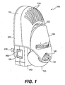
- FIG. 1 is a perspective view of a vaporizer incorporating a preferred rotatable plug assembly.
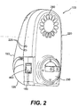
- FIG. 2 is a rotated perspective view of the vaporizer shown in FIG. 1.
- FIG. 3 is an exploded assembly view of the vaporizer shown in FIG. 1.
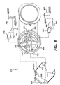
- FIG. 4 is an exploded assembly view of the rotatable plug assembly of the vaporizer shown in FIG. 1.
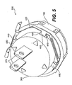
- FIG. 5 is a perspective view of the rotatable plug assembly shown in FIG. 4, configured for insertion into a vertical wall outlet.
- FIG. 6 is a perspective view of the rotatable plug assembly shown in FIG. 4, configured for insertion into a horizontal wall outlet.
- FIG. 7 is a schematic diagram of a preferred electrical circuit for the vaporizer shown in FIG. 1.
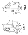
- FIGS. 8 and 9 are, respectively, rear and front perspective views of another vaporizer incorporating a preferred rotatable plug assembly.
- FIG. 10 is an exploded assembly view of the vaporizer shown in FIGS. 8 and 9.
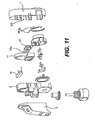
- FIG. 11 is a view, similar to that of FIG. 10, in which the vaporizer is provided with a fan.
- FIG. 12 is a view, similar to that of FIG. 10, but from a different viewpoint, in which the vaporizer is provided with a night light
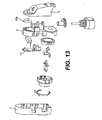
- FIG. 13 is a view, similar to that of FIG. 12, in which the vaporizer is provided with an indicator light.
- FIGS. 1-7 illustrate a vaporizer 100 incorporating a preferred rotatable plug assembly according to our invention.
- the vaporizer 100 comprises a multi-piece housing 110 in which a bottle 120 is detachably retained.
- the bottle 120 contains an evaporable substance (not shown), such as, for example, a liquid formulation including a chemical active such as an insecticide, fragrance, odor eliminator, or the like.
- a liquid formulation including a chemical active such as an insecticide, fragrance, odor eliminator, or the like.
- the term "bottle” is used herein in its broadest possible sense, including any receptacle, container, pouch, etc., capable of holding a liquid formulation.
- a raised pattern 130 on one side of the bottle is engaged by an opening 140 in a front shell 150 of the vaporizer housing 110, while a similar raised pattern (not shown) on an opposite side of the bottle 120 is engaged by a recess 170 (shown in FIG. 3) in a middle shell 180, in order to secure the bottle 120 within the vaporizer 100.
- the front shell 150 is sufficiently pliant so that pulling the bottle 120 in a downward direction causes the raised patterns 130 to release from the opening 140 in the front shell 150 and the recess 170 in the middle shell 180, respectively, thereby enabling removal of the bottle 120 from the vaporizer 100.
- the neck portion of the bottle may be designed to snap or screw into the vaporizer housing.
- Suitable refill bottles are available in a wide variety of liquid formulations from S.C. Johnson & Son, Inc., of Racine, Wisconsin, under the GLADE® PLUGINS® and RAID® brand names.
- the bottle 120 includes a wick 190 for drawing the liquid formulation out of the bottle 120 and toward an upper portion of the wick 190.
- a lower portion of the wick 190 is immersed in the liquid formulation, and the upper portion of the wick 190 protrudes above the neck of the bottle 120.
- the wick 190 is positioned within the bottle 120 by a cap 200 which includes a sheath 210 that encases the upper portion of the wick 190, except for an open area near the tip of the wick 190.
- a cap without a sheath can be utilized.
- the wick is about 7 mm in diameter and is constructed of ultra high molecular weight high density polyethylene.
- the vaporizer housing 110 comprises three shells ⁇ the front and middle shells 150, 180 noted above and a back shell 220 ⁇ which are fastened together by heat-staking or any other suitable fastening means, including, for example, rivets, press fit, snap fit, screws, ultrasonic welding, adhesives, or the like.
- the electrical components (discussed in more detail below) of the vaporizer 100 are housed within the space enclosed by the middle and back shells 180, 220.
- the back shell 220 contains a circular opening in which an electrical plug assembly 230 is seated.
- the plug assembly 230 serves the dual purpose of supplying power to the electrical components of the vaporizer 100 and also supporting the vaporizer 100 in a wall outlet (not shown).
- the plug assembly 230 is rotatable 360 degrees in order to support the vaporizer 100 in an upright position in both horizontal and vertical polarized wall outlets.
- the plug assembly 230 can be provided with an extra outlet 160 which is located on the side of the vaporizer 100 when the vaporizer is plugged into a vertical wall outlet (see FIGS. 1 and 5) and on the bottom of the vaporizer 100 when the vaporizer is plugged into a horizontal wall outlet (see FIG. 6).
- the plug assembly 230 comprises a stepped, cylindrically-shaped body 360.
- Plug blades 370 protrude through narrow slits 380 in the rear face of the plug assembly body 360, in a direction parallel to the axis of rotation of the plug assembly 230.
- each plug blade 370 includes a spring contact 390 at its distal end and a sliding contact 400.
- the sliding contacts 400 protrude slightly through openings 410 provided on opposite sides of the plug assembly body 360.
- the plug blades 370, including the spring contacts 390 and sliding contacts 400 preferably are made of nickel-plated brass, although other well-known conductive materials could also be utilized.
- the plug assembly 230 includes at least one, and preferably two, extra outlets 160.
- two extra outlets 160 are provided on opposite sides of the plug assembly body 360, spaced approximately 180 degrees apart from each other.
- a pair of rigid conductive members 420 are press fit over the spring contacts 390, thereby electrically connecting the extra outlets 160 to the plug blades 370.
- the conductive members 420 do not contact each other.
- the conductive members 420 are made of brass, although other well-known conductive materials could also be utilized.
- the plug assembly 230 rotates within a lower portion of the vaporizer housing 110.
- a pair of contact carriers 430 is fixed within the housing 110, substantially surrounding the cylindrical surface of the plug assembly 230.
- the contact carriers 430 are made of phosphor bronze, but other well-known conductive materials could also be utilized.
- the contact carriers 430 selectively provide an electrical connection between the plug assembly 230 and the electrical components of the vaporizer 100.
- the contact carriers 430 include four electrical contacts 440 spaced around the plug assembly 230 approximately 90 degrees apart from each other. Opposing pairs of contacts 440 are sized to receive the sliding contacts 400 of the plug blades 370 at each of four 90-degree intervals of rotation of the plug assembly 230.
- the sliding contacts 400 preferably are tapered along their edges, as indicated in FIG. 4.
- the plug assembly 230 is capable of conducting power to the electrical components of the vaporizer 100 at each of the four possible 90-degree intervals of rotation of the plug assembly 230.
- the plug assembly 230 of our invention is capable of being rotated in either direction any number of times, and still will provide the required electrical connections at each 90-degree interval of rotation.
- the vaporizer housing 110 includes three windows 460 ⁇ one on the bottom of the vaporizer 100 and one on each side.
- the windows 460 are positioned such that at least one of the extra outlets 160 is accessible through a window at at least two of the four possible 90-degree intervals of rotation of the plug assembly 230.
- the extra outlets 160 are aligned with windows 460 on opposite sides of the housing 110, whereas in the rotated orientation shown FIG. 6, only one of the extra outlets 160 is accessible through the window 460 in the bottom of the housing 110.
- the plug assembly 230 includes two extra outlets 160 on opposite sides thereof, at least one of the extra outlets 160 will be accessible at each of the four possible 90-degree intervals of rotation. If there is only one extra outlet, it will be accessible at three of the four 90-degree intervals of rotation.
- the vaporizer 100 can have just two windows 460 provided on mutually orthogonal sides of the housing 110, e.g., on the side and bottom.
- the plug assembly 230 includes two extra outlets 160 on opposite sides thereof, one of the extra outlets 160 will be accessible at each of the four possible 90-degree intervals of rotation. If there is only one extra outlet, it will be accessible at two of the four 90-degree intervals of rotation.
- the rotatable plug assembly 230 is incorporated in a liquid vaporizer, those skilled in the art will understand that the plug assembly can be utilized in many different types of wall-mounted, plug-in appliances, such as non-liquid fragrance dispensers, non-liquid insect control devices, night lights, timers, and the like.
- Each contact carrier 430 is electrically connected by a pin 600, 610 to a circuit board 240, which, in turn, is electrically connected to a heating device 250 and, preferably, also to a fan unit 260.
- the heating device 250 is disposed adjacent to a window 270 in the middle shell 180 which faces the tip of the wick 190 when the bottle 120 is inserted in the vaporizer 100. Heating the wick 190 enhances the rate at which the liquid formulation evaporates into the surrounding environment, as described more fully below.
- the heating device 250 is a 1.9 k ⁇ , 7 W metal oxide resistor potted in a ceramic block.
- the resistor preferably has PTC (positive temperature coefficient) characteristics, meaning that its resistance value increases slightly as the resistor heats up.
- PTC positive temperature coefficient
- a suitable resistor is available from Great Land Enterprise Co., Ltd., of Shenzhen, China, for example.
- the heating device 250 can comprise one or more other types of resistor heaters, a wire-wound heater, a PTC heater, or the like.
- the fan unit 260 is disposed within an upper portion of the housing 110.
- the back shell 220 includes air inlets 280 (shown in FIG. 2) for supplying air to the fan unit 260.
- the fan unit 260 creates an airstream that entrains the evaporated liquid formulation and assists in the dispersion of the chemical active into the surrounding environment.
- the flow rate of the fan unit 260 within the vaporizer 100 is approximately 0.5 cubic feet per minute, and the fan speed is approximately 2800-3800 RPM.
- a suitable fan unit 260 is a 12 V, DC, brushless fan, such as available from Power Logic Tech. Inc., of Tapei-Hsien, Taiwan.
- other DC or AC fans could be utilized, with appropriate adjustments to the circuit board 240, which is described more fully below.
- FIG. 7 is a schematic diagram of a preferred circuit board 240 for the vaporizer 100.
- the circuit board 240 is constructed of a flame-rated material.
- the pins 600, 610 of the circuit board 240 are provided in electrical contact with the respective contact carriers 430.
- the voltage applied across the pins 600, 610 is 120 V, at a frequency of 60 Hz.
- the heating device 250 is connected to the circuit board 240 by a pair of rivets 620, 630. Connected in parallel are (i) a 15 V, 1.3 W Zener diode 640, (ii) a 22 ⁇ F, 50 V aluminum electrolytic capacitor 650, rated for a temperature of 105°C, and (iii) the fan unit 260.
- the circuit board 240 also includes a 1N 4007 diode 660.
- the power consumption across the entire circuit is about 3.5 W to about 4.0 W.
- louver structure 290 Located downstream of the fan unit 260 is a louver structure 290, shown in FIG. 3, comprising at least one louver and, more preferably, a plurality of louvers 300.
- the louver structure 290 is an integral part of the middle shell 150, but it can also be provided separately from the middle shell 150.
- the louvers 300 are angled upwardly and away from the heating device 250 and the upper portion of the wick 190, preferably at an angle between about 20 degrees to about 60 degrees relative to horizontal when the vaporizer 100 is in an upright position.
- the optimum louver angle varies depending on such factors as the fan speed and the air exchange rate within the room in which the vaporizer 100 is located. In rooms with relatively low air exchange rates (e.g., between about 0.6 to about 1.2 exchanges per hour), a louver angle of about 40 degrees to about 45 degrees relative to horizontal is preferred. In rooms with higher air exchange rates, a louver angle of about 25 degrees to about 30 degrees relative to horizontal is preferred.
- the middle shell 180 is shaped so as to direct the airstream created by the fan unit 260 through the louvers 300. Notably, the middle shell 180 does not permit stray currents of air to recirculate within the housing 110, where those currents could have an undesirable cooling effect on the heating device 250.
- a pair of openings 225 shown in FIG. 2) in the side of the vaporizer 100 helps to achieve proper air circulation through the vaporizer.
- the front shell 150 includes a plurality of vents 310 through which the airstream exits the vaporizer 100 after passing through the louvers 300. As the airstream exits the vaporizer 100 through the vents 310, it entrains the evaporated liquid formulation, which rises from the wick 190 through an opening 320 in the front shell 150 below the vents 310.
- the vaporizer 100 also includes an adjustment mechanism 330 that positions the upper portion of the wick 190 with respect to the heating device 250.
- the adjustment mechanism 330 includes a hollow cylindrical portion 340 that surrounds and engages part of the upper portion of the wick 190, preferably at a location where the wick 190 is encased by the sheath 210.
- the adjustment mechanism 330 also includes a dial portion 350, accessible from outside the vaporizer housing 110, for rotating the cylindrical portion 340 about an axis of rotation. Rotating the dial portion 350 of the adjustment mechanism 330 causes the wick 190 to move toward or away from the heating device 250 in a lateral direction, i.e., in a direction substantially perpendicular to the longitudinal axis of the wick 190.
- FIGS. 8-13 Further preferred embodiments of our invention are illustrated in FIGS. 8-13.
- a vaporizer including a first shell 1 and a second shell 2 that can be joined together in any well-known manner, including rivets, screws, heat-staking, or the like.
- the first and second shells 1 and 2 together form the core housing structure of the vaporizer.
- the housing structure contains many of the basic functional components of the vaporizer, as well as one or more additional functional devices. As shown in FIGS.
- basic components of the vaporizer include a rotatable electrical plug assembly S, a contact carrier M having several electrical contacts, an electrical heating device R connected to a pair of contacts M R of the contact carrier M, a bottle F containing the liquid substance to be evaporated, and a wick W for drawing the liquid substance out of the bottle and toward an upper portion of the wick.
- the plug assembly S is of the sliding-contact type and has contacts S M for engagement with either of two possible corresponding pairs of contacts M S on the contact carrier M.
- the pairs of contacts M S on the contact carrier M are mutually offset by approximately 90 degrees, allowing the plug to be rotated through a range of 360 degrees. This makes the vaporizer easily adaptable for use in both horizontal and vertical electrical outlets, as are found in different parts of the world.
- the vaporizer is completed by a cover 3, which preferably surrounds substantially the entire outer surface of the second shell 2 such that substantially only the cover is visible when looking at the vaporizer head-on.
- the cover 3 is joined to the housing structure, preferably to the second shell 2, by any suitable fastening means.
- the cover 3 includes one or more access windows corresponding to whatever additional functional device(s) the vaporizer is equipped with. Apart from these minimal functional considerations, the cover design may be tailored to meet consumers' aesthetic preferences.
- An advantageous feature of our invention is that it permits any of several different additional functional devices to be incorporated in the vaporizer, without requiring any substantial modification to either the core housing structure or the basic functional components of the vaporizer.
- the housing structure in advance, is configured to receive any of the additional functional devices.
- the design of the cover 3, meanwhile, can be varied depending on the additional functional device(s) that the vaporizer is equipped with and the aesthetic preferences of a particular market.
- Additional functional devices for the vaporizer may include, for example, a draft regulator, a wick adjustment mechanism, a fan, a night light, an indicator light, a programmable user interface, or the like.
- the vaporizer includes an extra electrical outlet.
- a pair of metal strips 5 is provided within the body of the rotating plug assembly S. One end of each strip 5 is press-fitted into engagement with spring contacts on the pins of the plug, while the other end has a clamping system 5p for connecting to an electrical plug.
- the extra electrical outlet is accessible via either of two windows 5f provided in the first shell 1, depending on the position assumed by the plug assembly S.
- FIG. 11 illustrates a vaporizer including a fan as an additional functional device.
- the fan is housed in the top part of the first and second shells 1 and 2, which are provided, for this purpose, with a wide cavity.
- This cavity houses a printed electrical circuit 10 and a fan assembly 11 that is powered and controlled by the circuit 10.
- the circuit 10 is in turn powered by means of a pair of contacts M 10 (which is precisely the same pair of contacts M R described above in connection with FIG. 10).
- the heating device R is connected to the circuit 10 instead of directly to the contact carrier M.
- the circuit 10 is equipped with a switch 10a that is accessible through a window 10fin the first shell 1.
- FIG. 12 illustrates a vaporizer including a night light 12 as an additional functional device.
- the night light 12 may be chosen from among various well-known types of commercially-available devices, such as incandescent lamps, neon lamps, LED devices (as shown in FIG. 12), or the like. If desired, a diffusing lens 12a may also be utilized.
- the electrical connections in this embodiment are identical to those discussed above with respect to FIG. 11.
- FIG. 13 illustrates a vaporizer including a programmable user interface 13 as an additional functional device.
- the interface includes three LED devices.
- the LED devices preferably have a much lower wattage than those used in the night light embodiment, because they are not intended to provide illumination, but rather only signal the different operating modes of the vaporizer.
- a diffusing lens 13a may also be used in this embodiment, if desired.
- the electrical connections in this embodiment are identical to those discussed above with respect to FIG. 11.
- the vaporizer can simply be provided with a cover 3 having the desired aesthetic characteristics and only those access windows that are necessary based on the particular additional functional devices that the vaporizer is equipped with.
- the additional functional devices are easily inserted into their respective places and connected to the electrical contacts already provided-in the first and second shells 1 and 2.
Landscapes
- Life Sciences & Earth Sciences (AREA)
- Pest Control & Pesticides (AREA)
- Engineering & Computer Science (AREA)
- Health & Medical Sciences (AREA)
- General Health & Medical Sciences (AREA)
- Insects & Arthropods (AREA)
- General Engineering & Computer Science (AREA)
- Mechanical Engineering (AREA)
- Combustion & Propulsion (AREA)
- Toxicology (AREA)
- Chemical & Material Sciences (AREA)
- Wood Science & Technology (AREA)
- Zoology (AREA)
- Environmental Sciences (AREA)
- Epidemiology (AREA)
- Animal Behavior & Ethology (AREA)
- Public Health (AREA)
- Veterinary Medicine (AREA)
- Catching Or Destruction (AREA)
- Connector Housings Or Holding Contact Members (AREA)
- Control Of Steam Boilers And Waste-Gas Boilers (AREA)
- Coupling Device And Connection With Printed Circuit (AREA)
Claims (25)
- Einsteckgerät (100) für die Wandmontage mit:einem Gehäuse (110), in dem sich die elektrischen Bauteile des Geräts befinden und das eine Vielzahl von Fenstern (460) enthält; undeiner Steckeranordnung (230), die drehbar im Gehäuse (110) angeordnet ist und (i) einen Stecker zum elektrischen Verbinden der Steckeranordnung mit einer Wandsteckdose und (ii) mindestens einen integrierten Zusatz-Steckanschluss (160) aufweist, an den ein anderes Elektrogerät ansteckbar ist;wobei die Steckeranordnung (230) in jeder von mindestens zwei 90°-Drehintervallen den elektrischen Bauteilen des Geräts elektrischen Strom zuführt und in unterschiedlichen 90°-Drehintervallen der Steckeranordnung (230) der Zusatz-Steckanschluss (160) durch unterschiedliche Fenster der Vielzahl der Fenster (460) im Gehäuse zugänglich ist.
- Einsteckgerät nach Anspruch 1, dessen im Gehäuse enthaltenen elektrischen Bauteile mindestens eines der folgenden Bauteile aufweist: eine Heizeinrichtung, ein Gebläse, eine Leuchte oder eine Schaltungsplatine.
- Einsteckgerät nach Anspruch 1, bei dem zwei zueinander rechtwinklige Seiten des Gehäuses jeweils eines der Vielzahl von Fenstern enthalten und die beiden Gehäuseseiten an eine dritte Gehäuseseite, aus der der Stecker der Steckeranordnung hervorragt, angrenzen und rechtwinklig zu dieser dritten Gehäuseseite liegen.
- Einsteckgerät nach Anspruch 1, bei der ein Paar starrer leitfähiger Elemente den Zusatz-Steckanschluss elektrisch mit dem Stecker verbindet.
- Einsteckgerät nach Anspruch 4, dessen Steckeranordnung im wesentlichen zylindrisch ist und zwei integrierte Zusatz-Steckanschlüsse aufweist, die auf der Zylinderfläche der Steckeranordnung um etwa 180° beabstandet sind.
- Einsteckgerät nach Anspruch 5, bei dem ein Paar starrer leitfähiger Elemente die Zusatzanschlüsse mit dem Stecker verbindet.
- Einsteckgerät (100) zur Wandmontage mit:einem Gehäuse (110), in dem sich die elektrischen Bauteile des Geräts befinden und das eine Vielzahl von Fenstern (460) enthält; undeiner Steckeranordnung (230), die drehbar im Gehäuse (110) angeordnet ist und (i) einen Satz Kontaktmesser (370), die parallel zur Drehachse der Steckeranordnung (230) verlaufen und mit denen letztere mit einer Wandsteckdose verbindbar ist, und (ii) mindestens einen integrierten Zusatz-Steckanschluss (160) zur Aufnahme eines Satzes Kontaktmesser eines anderen Elektrogeräts aufweist, wobei der Zusatz-Steckanschluss (160) so gerichtet ist, dass die Kontaktmesser des anderen Elektrogeräts, wenn in den Zusatz-Steckanschluss gesteckt, im wesentlichen rechtwinklig zur Drehachse der Steckeranordnung verlaufen; undwobei die Steckeranordnung (230) in jeder von mindestens zwei 90°-Drehintervallen die elektrischen Bauteile des Geräts mit der Wandsteckdose verbindet und in mindestens zwei der vier 90°-Drehintervallen der Steckeranordnung (230) der Zusatz-Steckanschluss (160) durch unterschiedliche Fenster der Vielzahl der Fenster (460) im Gehäuse (110) zugänglich ist.
- Gerät nach Anspruch 7, bei dem in mindestens drei der vier 90°-Drehintervalle der Zusatz-Steckanschluss durch unterschiedliche Fenster der Vielzahl der Fenster im Gehäuse hindurch zugänglich ist.
- Gerät nach Anspruch 7, dessen im Gehäuse enthaltenen elektrischen Bauteile mindestens eines der folgenden Bauteile aufweist: eine Heizeinrichtung, ein Gebläse, eine Leuchte oder eine Schaltungsplatine.
- Gerät nach Anspruch 7, bei dem zwei zueinander rechtwinklige Seiten des Gehäuses jeweils eine der Vielzahl von Fenstern enthalten und die beiden Seiten jeweils an eine dritte Gehäuseseite, aus der die Kontaktmesser der Steckeranordnung heraus ragen, angrenzen und im wesentlichen rechtwinklig zu dieser dritten Gehäuseseite verlaufen.
- Gerät nach Anspruch 7, bei dem ein Paar starrer leitfähiger Elemente den Zusatz-Steckanschluss elektrisch mit den Kontaktmessern der Steckeranordnung verbindet.
- Gerät nach Anspruch 11, dessen Steckeranordnung im wesentlichen zylindrisch ist und zwei integrierte Zusatz-Steckanschlüsse aufweist, die auf der zylindrischen Oberfläche der Steckeranordnung um etwa 180° beabstandet sind.
- Gerät nach Anspruch 12, bei der das Paar starrer leitfähiger Elemente die Zusatz-Steckanschlüsse mit den Messerkontakten der Steckeranordnung verbindet.
- Elektro-Einsteckgerät (100) zum Verteilen eines chemischen Wirkstoffs in der Umluft, das aufweist:ein Gehäuse (110) mit einer Vielzahl von Fenstern (460);mindestens ein elektrisches Bauteil, das im Gehäuse angeordnet ist, um das Verteilen des chemischen Wirkstoffs in der Umluft zu verbessern; undeine Steckeranordnung (230), die drehbar im Gehäuse (110) angeordnet ist und (i) einen Stecker zum elektrischen Verbinden der Steckeranordnung mit einer Wandsteckdose und (ii) mindestens einen integrierten Zusatz-Steckanschluss (160) aufweist, an den ein anderes Elektrogerät ansteckbar ist;wobei die Steckeranordnung (230) dem mindestens einen elektrischen Bauteil in jeder ihrer mindestens zwei 90°-Drehintervalle Strom zuführt und in unterschiedlichen 90°-Drehintervallen der Steckeranordnung der Zusatz-Steckanschluss (160) durch unterschiedliche Fenster der Vielzahl von Fenstern (460) im Gehäuse (110) zugänglich ist.
- Gerät nach Anspruch 14, bei dem das mindestens eine elektrische Bauteil entweder eine Heizeinrichtung oder ein Gebläse aufweist.
- Gerät nach Anspruch 14, bei dem zwei zueinander rechtwinklige Gehäuseseiten jeweils eines der Vielzahl von Fenstern enthalten und die beiden Seiten an eine dritte Gehäuseseite, aus der der Stecker hervorragt, angrenzen und zu dieser dritten Gehäuseseite im wesentlichen rechtwinklig liegen.
- Gerät nach Anspruch 14, bei dem ein Paar starrer leitfähiger Elemente den Zusatz-Steckanschluss mit dem Stecker verbindet.
- Gerät nach Anspruch 17, dessen Steckeranordnung im wesentlichen zylindrisch ist und zwei integrierte Zusatz-Steckanschlüsse aufweist, die auf der zylindrischen Oberfläche der Steckeranordnung um etwa 180° beabstandet sind.
- Gerät nach Anspruch 18, bei dem das Paar starrer leitfähiger Elemente die Zusatz-Steckanschlüsse jeweils elektrisch mit dem Stecker verbindet.
- Einsteck-Verdunster (100) zum Verteilen eines chemischen Wirkstoffs in der Umluft, der aufweist:eine Flasche (120) mit einem flüssigen Ansatz, der mindestens einen chemischen Wirkstoff enthält;einen Docht (190), der mit einem unteren Teil in die Flasche hinein und mit einem oberen Teil aus der Flasche hervor ragt, um den Flüssigansatz aus der Flasche zum Docht-Oberteil zu ziehen;ein Gehäuse (110), in dem die Flasche (120) herausnehmbar gehaltert ist und das eine Vielzahl von Fenstern (460) enthält;eine elektrische Heizeinrichtung (250), die im Gehäuse nahe dem Docht-Oberteil angeordnet ist, um das Verdunsten des Flüssigansatzes aus dem Docht-Oberteil zu verstärken; undeine Steckeranordnung (230), die drehbar im Gehäuse (110) angeordnet ist, um der Heizeinrichtung (250) elektrischen Strom zuzuführen, wobei die Steckeranordnung (230) (i) einen Satz Kontaktmesser (370), die parallel zur Drehachse der Steckeranordnung verlaufen und diese elektrisch mit einer Wandsteckdose verbinden, und (ii) mindestens einen integrierten Zusatz-Steckanschluss (160) zur Aufnahme des Kontaktmessersatzes eines anderen Elektrogeräts aufweist, wobei der Zusatz-Steckanschluss (160) so orientiert ist, dass die Kontaktmesser des anderen Elektrogeräts, wenn in den Zusatz-Steckanschluss eingesteckt, im wesentlichen rechtwinklig zur Drehachse der Steckeranordnung (230) vorstehen;wobei die Steckeranordnung (230) die elektrischen Bauteile des Geräts in jeder von vier 90°-Drehintervallen der Steckeranordnung mit der Wandsteckdose elektrisch verbindet und der Zusatz-Steckanschluss (160) in mindestens zwei der vier 90°-Drehintervalle durch unterschiedliche Fenster der Vielzahl der Fenster (460) im Gehäuse (110) zugänglich ist.
- Verdunster nach Anspruch 20, dessen Zusatz-Steckanschluss in mindestens drei der vier 90°-Drehintervallen durch unterschiedliche Fenster der Vielzahl der Fenster im Gehäuse zugänglich ist.
- Verdunster nach Anspruch 20, bei dem zwei untereinander rechtwinklige Seiten des Gehäuses jeweils ein Fenster aus der Vielzahl der Fenster enthalten und die beiden Seiten jeweils an eine dritte Gehäuseseite, aus der heraus die Kontaktmesser der Steckeranordnung vorstehen, angrenzen und im wesentlichen rechtwinklig zu dieser dritten Gehäuseseite liegen.
- Verdunster nach Anspruch 20, bei dem ein Paar starrer leitfähiger Elemente den Zusatz-Steckanschluss elektrisch mit den Kontaktmessern der Steckeranordnung verbindet.
- Verdunster nach Anspruch 23, dessen Steckeranordnung im wesentlichen zylindrisch ist und zwei integrierte Zusatz-Steckanschlüsse aufweist, die auf der zylindrischen Oberfläche der Steckeranordnung um etwa 180° beabstandet sind.
- Verdunster nach Anspruch 24, bei dem ein Paar starrer leitfähiger Elemente die Zusatz-Steckanschlüsse elektrisch mit den Kontaktmessern der Steckeranordnung verbindet.
Applications Claiming Priority (3)
| Application Number | Priority Date | Filing Date | Title |
|---|---|---|---|
| US37116202P | 2002-04-10 | 2002-04-10 | |
| US371162P | 2002-04-10 | ||
| PCT/US2003/003441 WO2003088430A1 (en) | 2002-04-10 | 2003-02-06 | Rotatable plug assembly including an extra outlet |
Publications (2)
| Publication Number | Publication Date |
|---|---|
| EP1493210A1 EP1493210A1 (de) | 2005-01-05 |
| EP1493210B1 true EP1493210B1 (de) | 2006-05-03 |
Family
ID=29250650
Family Applications (1)
| Application Number | Title | Priority Date | Filing Date |
|---|---|---|---|
| EP03710866A Expired - Lifetime EP1493210B1 (de) | 2002-04-10 | 2003-02-06 | Drehverbinderanordnung mit einer zusätzlichen steckdose |
Country Status (10)
| Country | Link |
|---|---|
| EP (1) | EP1493210B1 (de) |
| CN (1) | CN100438228C (de) |
| AT (1) | ATE325450T1 (de) |
| AU (1) | AU2003215013B8 (de) |
| BR (1) | BR0309155A (de) |
| CA (1) | CA2481608C (de) |
| DE (2) | DE60305021T2 (de) |
| ES (1) | ES2259136T3 (de) |
| MX (1) | MXPA04009845A (de) |
| WO (1) | WO2003088430A1 (de) |
Families Citing this family (9)
| Publication number | Priority date | Publication date | Assignee | Title |
|---|---|---|---|---|
| WO2006023796A1 (en) * | 2004-08-20 | 2006-03-02 | The Dial Corporation | Methods and apparatus for a low-profile air purifier |
| US20070194144A1 (en) * | 2006-02-22 | 2007-08-23 | Davis Brian T | Air treatment device with heated volatile dispenser |
| CN201078817Y (zh) | 2007-04-05 | 2008-06-25 | 陆航 | 防尘usb集线器 |
| GB2464523A (en) * | 2008-10-20 | 2010-04-21 | Chin-Sheng Yang | Aroma plug-in lamp with fan |
| US8821171B2 (en) * | 2011-09-22 | 2014-09-02 | S.C. Johnson & Son, Inc. | Rotatable plug assembly and housing for a volatile material dispenser |
| US8858236B2 (en) | 2011-10-28 | 2014-10-14 | S.C. Johnson & Son, Inc. | Rotatable plug assembly and method of reducing strain in a wire |
| ES2530899B1 (es) | 2013-05-08 | 2016-01-05 | Zobele España, S.A. | Dispositivo de evaporación de sustancias volátiles |
| US10994042B2 (en) * | 2016-01-25 | 2021-05-04 | S. C. Johnson & Son, Inc. | Heated air freshener |
| US10764963B2 (en) * | 2016-10-07 | 2020-09-01 | S. C. Johnson & Son, Inc. | Volatile material dispenser |
Family Cites Families (7)
| Publication number | Priority date | Publication date | Assignee | Title |
|---|---|---|---|---|
| US4804821A (en) * | 1986-06-24 | 1989-02-14 | Environmental Fragrance Technologies, Ltd. | Aroma diffuser assembly |
| US4743999A (en) * | 1987-02-13 | 1988-05-10 | Curtis Manufacturing Company, Inc. | Rotary telephone line surge protector and system |
| FR2664102B1 (fr) * | 1990-06-28 | 1994-11-10 | Moulinex Sa | Connecteur electrique amovible destine a etre installe entre un appareil de consommation electrique et une prise de courant murale. |
| US5554039A (en) * | 1995-09-29 | 1996-09-10 | Siemens Electric Limited | Quick plug connector for electric distribution system(s) |
| US5647053A (en) * | 1995-10-11 | 1997-07-08 | S. C. Johnson & Son, Inc. | Vapor dipensing device |
| US5957701A (en) * | 1997-06-06 | 1999-09-28 | Mcmillin; Kenneth G. | Electrical outlet extension |
| ITMI981276A1 (it) * | 1998-06-05 | 1999-12-05 | Zobele Ind Chim | Vaporizzatore elettrico di insetticidi o profumi in formulazioni liquide con dispositivo di regolazione della intensita' di |
-
2003
- 2003-02-06 CA CA002481608A patent/CA2481608C/en not_active Expired - Fee Related
- 2003-02-06 ES ES03710866T patent/ES2259136T3/es not_active Expired - Lifetime
- 2003-02-06 DE DE60305021T patent/DE60305021T2/de not_active Expired - Fee Related
- 2003-02-06 AT AT03710866T patent/ATE325450T1/de not_active IP Right Cessation
- 2003-02-06 CN CNB038117991A patent/CN100438228C/zh not_active Expired - Fee Related
- 2003-02-06 EP EP03710866A patent/EP1493210B1/de not_active Expired - Lifetime
- 2003-02-06 AU AU2003215013A patent/AU2003215013B8/en not_active Ceased
- 2003-02-06 MX MXPA04009845A patent/MXPA04009845A/es active IP Right Grant
- 2003-02-06 WO PCT/US2003/003441 patent/WO2003088430A1/en not_active Ceased
- 2003-02-06 BR BR0309155-4A patent/BR0309155A/pt not_active IP Right Cessation
- 2003-04-07 DE DE60328174T patent/DE60328174D1/de not_active Expired - Lifetime
Also Published As
| Publication number | Publication date |
|---|---|
| WO2003088430A1 (en) | 2003-10-23 |
| CN100438228C (zh) | 2008-11-26 |
| AU2003215013A1 (en) | 2003-10-27 |
| DE60328174D1 (de) | 2009-08-13 |
| DE60305021T2 (de) | 2006-08-31 |
| BR0309155A (pt) | 2005-01-25 |
| ATE325450T1 (de) | 2006-06-15 |
| CN1656657A (zh) | 2005-08-17 |
| MXPA04009845A (es) | 2005-02-17 |
| ES2259136T3 (es) | 2006-09-16 |
| DE60305021D1 (de) | 2006-06-08 |
| CA2481608A1 (en) | 2003-10-23 |
| EP1493210A1 (de) | 2005-01-05 |
| AU2003215013B8 (en) | 2008-05-01 |
| AU2003215013B2 (en) | 2008-04-17 |
| CA2481608C (en) | 2008-09-16 |
Similar Documents
| Publication | Publication Date | Title |
|---|---|---|
| US6862403B2 (en) | Rotatable plug assembly including an extra outlet | |
| EP1492574B1 (de) | Elektrischer verdampfer mit vorrichtung zur regelung der dampfintensität | |
| EP1283062B1 (de) | Elektrischer polyfunktioneller Wandsteckdosenverdampfer | |
| CA2481487C (en) | Electrical evaporator including fan and louver structure | |
| US6957012B2 (en) | Method and apparatus for dual-outlet vapor dispenser | |
| CA2423814C (en) | Modular electrical device for delivery of volatile compounds | |
| CA2402868C (en) | Night light air freshener | |
| EP1685856A2 (de) | Elektrischer Evaporator mit Docht-Anpassung durch ein Klinkwerk | |
| AU2001243552A1 (en) | Night light air freshener | |
| EP1493210B1 (de) | Drehverbinderanordnung mit einer zusätzlichen steckdose | |
| ES2237642T3 (es) | Dispositivo calentador para electrodifusor. | |
| EP1393754B1 (de) | Verdampfer mit doppelten elektrischen Anschluss | |
| MXPA03007341A (en) | Method and apparatus for dual-outlet vapor dispenser |
Legal Events
| Date | Code | Title | Description |
|---|---|---|---|
| PUAI | Public reference made under article 153(3) epc to a published international application that has entered the european phase |
Free format text: ORIGINAL CODE: 0009012 |
|
| 17P | Request for examination filed |
Effective date: 20041006 |
|
| AK | Designated contracting states |
Kind code of ref document: A1 Designated state(s): AT BE BG CH CY CZ DE DK EE ES FI FR GB GR HU IE IT LI LU MC NL PT SE SI SK TR |
|
| AX | Request for extension of the european patent |
Extension state: AL LT LV MK RO |
|
| GRAP | Despatch of communication of intention to grant a patent |
Free format text: ORIGINAL CODE: EPIDOSNIGR1 |
|
| GRAS | Grant fee paid |
Free format text: ORIGINAL CODE: EPIDOSNIGR3 |
|
| GRAA | (expected) grant |
Free format text: ORIGINAL CODE: 0009210 |
|
| AK | Designated contracting states |
Kind code of ref document: B1 Designated state(s): AT BE BG CH CY CZ DE DK EE ES FI FR GB GR HU IE IT LI LU MC NL PT SE SI SK TR |
|
| PG25 | Lapsed in a contracting state [announced via postgrant information from national office to epo] |
Ref country code: SI Free format text: LAPSE BECAUSE OF FAILURE TO SUBMIT A TRANSLATION OF THE DESCRIPTION OR TO PAY THE FEE WITHIN THE PRESCRIBED TIME-LIMIT Effective date: 20060503 Ref country code: NL Free format text: LAPSE BECAUSE OF FAILURE TO SUBMIT A TRANSLATION OF THE DESCRIPTION OR TO PAY THE FEE WITHIN THE PRESCRIBED TIME-LIMIT Effective date: 20060503 Ref country code: LI Free format text: LAPSE BECAUSE OF FAILURE TO SUBMIT A TRANSLATION OF THE DESCRIPTION OR TO PAY THE FEE WITHIN THE PRESCRIBED TIME-LIMIT Effective date: 20060503 Ref country code: FI Free format text: LAPSE BECAUSE OF FAILURE TO SUBMIT A TRANSLATION OF THE DESCRIPTION OR TO PAY THE FEE WITHIN THE PRESCRIBED TIME-LIMIT Effective date: 20060503 Ref country code: CH Free format text: LAPSE BECAUSE OF FAILURE TO SUBMIT A TRANSLATION OF THE DESCRIPTION OR TO PAY THE FEE WITHIN THE PRESCRIBED TIME-LIMIT Effective date: 20060503 Ref country code: BE Free format text: LAPSE BECAUSE OF FAILURE TO SUBMIT A TRANSLATION OF THE DESCRIPTION OR TO PAY THE FEE WITHIN THE PRESCRIBED TIME-LIMIT Effective date: 20060503 Ref country code: CZ Free format text: LAPSE BECAUSE OF FAILURE TO SUBMIT A TRANSLATION OF THE DESCRIPTION OR TO PAY THE FEE WITHIN THE PRESCRIBED TIME-LIMIT Effective date: 20060503 Ref country code: SK Free format text: LAPSE BECAUSE OF FAILURE TO SUBMIT A TRANSLATION OF THE DESCRIPTION OR TO PAY THE FEE WITHIN THE PRESCRIBED TIME-LIMIT Effective date: 20060503 Ref country code: AT Free format text: LAPSE BECAUSE OF FAILURE TO SUBMIT A TRANSLATION OF THE DESCRIPTION OR TO PAY THE FEE WITHIN THE PRESCRIBED TIME-LIMIT Effective date: 20060503 Ref country code: IT Free format text: LAPSE BECAUSE OF FAILURE TO SUBMIT A TRANSLATION OF THE DESCRIPTION OR TO PAY THE FEE WITHIN THE PRESCRIBED TIME-LIMIT;WARNING: LAPSES OF ITALIAN PATENTS WITH EFFECTIVE DATE BEFORE 2007 MAY HAVE OCCURRED AT ANY TIME BEFORE 2007. THE CORRECT EFFECTIVE DATE MAY BE DIFFERENT FROM THE ONE RECORDED. Effective date: 20060503 |
|
| REG | Reference to a national code |
Ref country code: GB Ref legal event code: FG4D |
|
| REG | Reference to a national code |
Ref country code: CH Ref legal event code: EP |
|
| REF | Corresponds to: |
Ref document number: 60305021 Country of ref document: DE Date of ref document: 20060608 Kind code of ref document: P |
|
| REG | Reference to a national code |
Ref country code: IE Ref legal event code: FG4D |
|
| PG25 | Lapsed in a contracting state [announced via postgrant information from national office to epo] |
Ref country code: SE Free format text: LAPSE BECAUSE OF FAILURE TO SUBMIT A TRANSLATION OF THE DESCRIPTION OR TO PAY THE FEE WITHIN THE PRESCRIBED TIME-LIMIT Effective date: 20060803 Ref country code: DK Free format text: LAPSE BECAUSE OF FAILURE TO SUBMIT A TRANSLATION OF THE DESCRIPTION OR TO PAY THE FEE WITHIN THE PRESCRIBED TIME-LIMIT Effective date: 20060803 |
|
| REG | Reference to a national code |
Ref country code: ES Ref legal event code: FG2A Ref document number: 2259136 Country of ref document: ES Kind code of ref document: T3 |
|
| PG25 | Lapsed in a contracting state [announced via postgrant information from national office to epo] |
Ref country code: PT Free format text: LAPSE BECAUSE OF FAILURE TO SUBMIT A TRANSLATION OF THE DESCRIPTION OR TO PAY THE FEE WITHIN THE PRESCRIBED TIME-LIMIT Effective date: 20061003 |
|
| NLV1 | Nl: lapsed or annulled due to failure to fulfill the requirements of art. 29p and 29m of the patents act | ||
| REG | Reference to a national code |
Ref country code: CH Ref legal event code: PL |
|
| ET | Fr: translation filed | ||
| PG25 | Lapsed in a contracting state [announced via postgrant information from national office to epo] |
Ref country code: MC Free format text: LAPSE BECAUSE OF NON-PAYMENT OF DUE FEES Effective date: 20070228 |
|
| PLBE | No opposition filed within time limit |
Free format text: ORIGINAL CODE: 0009261 |
|
| STAA | Information on the status of an ep patent application or granted ep patent |
Free format text: STATUS: NO OPPOSITION FILED WITHIN TIME LIMIT |
|
| 26N | No opposition filed |
Effective date: 20070206 |
|
| PG25 | Lapsed in a contracting state [announced via postgrant information from national office to epo] |
Ref country code: IE Free format text: LAPSE BECAUSE OF NON-PAYMENT OF DUE FEES Effective date: 20070206 |
|
| PG25 | Lapsed in a contracting state [announced via postgrant information from national office to epo] |
Ref country code: GR Free format text: LAPSE BECAUSE OF FAILURE TO SUBMIT A TRANSLATION OF THE DESCRIPTION OR TO PAY THE FEE WITHIN THE PRESCRIBED TIME-LIMIT Effective date: 20060804 |
|
| PGFP | Annual fee paid to national office [announced via postgrant information from national office to epo] |
Ref country code: ES Payment date: 20080226 Year of fee payment: 6 |
|
| PG25 | Lapsed in a contracting state [announced via postgrant information from national office to epo] |
Ref country code: BG Free format text: LAPSE BECAUSE OF FAILURE TO SUBMIT A TRANSLATION OF THE DESCRIPTION OR TO PAY THE FEE WITHIN THE PRESCRIBED TIME-LIMIT Effective date: 20060803 |
|
| PG25 | Lapsed in a contracting state [announced via postgrant information from national office to epo] |
Ref country code: EE Free format text: LAPSE BECAUSE OF FAILURE TO SUBMIT A TRANSLATION OF THE DESCRIPTION OR TO PAY THE FEE WITHIN THE PRESCRIBED TIME-LIMIT Effective date: 20060503 |
|
| PGFP | Annual fee paid to national office [announced via postgrant information from national office to epo] |
Ref country code: DE Payment date: 20080331 Year of fee payment: 6 Ref country code: FR Payment date: 20080218 Year of fee payment: 6 |
|
| PGFP | Annual fee paid to national office [announced via postgrant information from national office to epo] |
Ref country code: GB Payment date: 20090227 Year of fee payment: 7 |
|
| PG25 | Lapsed in a contracting state [announced via postgrant information from national office to epo] |
Ref country code: LU Free format text: LAPSE BECAUSE OF NON-PAYMENT OF DUE FEES Effective date: 20070206 Ref country code: CY Free format text: LAPSE BECAUSE OF FAILURE TO SUBMIT A TRANSLATION OF THE DESCRIPTION OR TO PAY THE FEE WITHIN THE PRESCRIBED TIME-LIMIT Effective date: 20060503 |
|
| PGFP | Annual fee paid to national office [announced via postgrant information from national office to epo] |
Ref country code: IT Payment date: 20090224 Year of fee payment: 7 |
|
| PG25 | Lapsed in a contracting state [announced via postgrant information from national office to epo] |
Ref country code: TR Free format text: LAPSE BECAUSE OF FAILURE TO SUBMIT A TRANSLATION OF THE DESCRIPTION OR TO PAY THE FEE WITHIN THE PRESCRIBED TIME-LIMIT Effective date: 20060503 Ref country code: HU Free format text: LAPSE BECAUSE OF FAILURE TO SUBMIT A TRANSLATION OF THE DESCRIPTION OR TO PAY THE FEE WITHIN THE PRESCRIBED TIME-LIMIT Effective date: 20061104 |
|
| REG | Reference to a national code |
Ref country code: FR Ref legal event code: ST Effective date: 20091030 |
|
| PG25 | Lapsed in a contracting state [announced via postgrant information from national office to epo] |
Ref country code: DE Free format text: LAPSE BECAUSE OF NON-PAYMENT OF DUE FEES Effective date: 20090901 |
|
| REG | Reference to a national code |
Ref country code: ES Ref legal event code: FD2A Effective date: 20090207 |
|
| PG25 | Lapsed in a contracting state [announced via postgrant information from national office to epo] |
Ref country code: FR Free format text: LAPSE BECAUSE OF NON-PAYMENT OF DUE FEES Effective date: 20090302 |
|
| PG25 | Lapsed in a contracting state [announced via postgrant information from national office to epo] |
Ref country code: ES Free format text: LAPSE BECAUSE OF NON-PAYMENT OF DUE FEES Effective date: 20090207 |
|
| GBPC | Gb: european patent ceased through non-payment of renewal fee |
Effective date: 20100206 |
|
| PG25 | Lapsed in a contracting state [announced via postgrant information from national office to epo] |
Ref country code: GB Free format text: LAPSE BECAUSE OF NON-PAYMENT OF DUE FEES Effective date: 20100206 Ref country code: IT Free format text: LAPSE BECAUSE OF NON-PAYMENT OF DUE FEES Effective date: 20100206 |