EP1493326A1 - Knotereinrichtung für eine Grossballenpresse - Google Patents
Knotereinrichtung für eine Grossballenpresse Download PDFInfo
- Publication number
- EP1493326A1 EP1493326A1 EP04013455A EP04013455A EP1493326A1 EP 1493326 A1 EP1493326 A1 EP 1493326A1 EP 04013455 A EP04013455 A EP 04013455A EP 04013455 A EP04013455 A EP 04013455A EP 1493326 A1 EP1493326 A1 EP 1493326A1
- Authority
- EP
- European Patent Office
- Prior art keywords
- knotter
- shaft
- knotting device
- needle
- press channel
- Prior art date
- Legal status (The legal status is an assumption and is not a legal conclusion. Google has not performed a legal analysis and makes no representation as to the accuracy of the status listed.)
- Granted
Links
- 230000008878 coupling Effects 0.000 claims description 5
- 238000010168 coupling process Methods 0.000 claims description 5
- 238000005859 coupling reaction Methods 0.000 claims description 5
- 230000001419 dependent effect Effects 0.000 claims 1
- 230000015572 biosynthetic process Effects 0.000 description 5
- 238000000034 method Methods 0.000 description 4
- 238000010276 construction Methods 0.000 description 1
- 230000002349 favourable effect Effects 0.000 description 1
- 238000003780 insertion Methods 0.000 description 1
- 230000037431 insertion Effects 0.000 description 1
- 230000007257 malfunction Effects 0.000 description 1
- 230000001960 triggered effect Effects 0.000 description 1
Images

Classifications
-
- A—HUMAN NECESSITIES
- A01—AGRICULTURE; FORESTRY; ANIMAL HUSBANDRY; HUNTING; TRAPPING; FISHING
- A01F—PROCESSING OF HARVESTED PRODUCE; HAY OR STRAW PRESSES; DEVICES FOR STORING AGRICULTURAL OR HORTICULTURAL PRODUCE
- A01F15/00—Baling presses for straw, hay or the like
- A01F15/08—Details
- A01F15/14—Tying devices specially adapted for baling presses
- A01F15/145—Twine knotters
Definitions
- the invention relates to a knotter device for a large baler, in particular for agricultural crop, according to the preamble of claim 1.
- the invention is based on the object, the position of the knotter device during the pressing and binding process the optimal requirements automatically adapt, allowing a trouble-free and functionally safe working under all operating states is possible.
- the inventive pivoting device of the knotter device are the functional elements at any time in the most favorable functional Position, so that no mistakes in the formation and deduction of the Node occur.
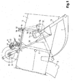
- the end of the tie rod 10 is connected to a needle rocker 11, which an axle 12 is pivotally mounted.
- the free end of the needle rocker 11 is in driving connection with the binding needles 7.
- In the area of the axis 12 is a rigidly connected to the needle rocker 11 tab 13 with an inner curve guide 14 arranged.
- the coupling rod 16 is connected to a Shaft 17 connected to a bearing block 18 on the upper wall 5 of the Press channel 1 is mounted pivotably.
- the shaft 17 is provided with a lever arm 19 connected at the free end of a connecting rod 20 hinged is hingedly connected to a lower base plate 21 of the knotter device 6 is.
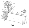
- the thus caused, pivoting movement of the Shaft 17 is connected via the lever arm 19 and the connecting rod 20 to the Base plate 21 passed, whereby this is moved accordingly.
- the base plate 21 is fixedly connected to the frame 22 of the knotter device 6.
- the frame 22 is pivotally mounted on the knotter shaft 23. Depending on the particular Position of the binding needles 7, the entire knotter device 6 with their Function elements automatically pivoted about the knotter shaft 23.
- each knotter device 6 has a drive pulley 27, the rotationally movable and movable in the axial direction on the Knoterwelle 23 is attached.
- the drive pulleys 27 each have an outer Tooth segment 28 and an inner toothed segment 29.
- the outer tooth segments 28 serve to drive the Knoterschnabels 26 and the inner tooth segments 29 for driving the Garnklemmrades 25.
- All individual functional elements of the knotter device 6 are connected to a common Frame 22 is arranged, which is mounted on the knotter shaft 23 and around this is pivotable.
- the arranged in the lower region of the frame 22 profiled Base plate 21 is loosely against the upper wall 5 of the press channel 2.
Landscapes
- Life Sciences & Earth Sciences (AREA)
- Environmental Sciences (AREA)
- Binders And Loading Units For Sheaves (AREA)
- Basic Packing Technique (AREA)
- Threshing Machine Elements (AREA)
Abstract
Description
- Fig. 1
- den Presskanal einer Großballenpresse mit dem Bereich der Knotereinrichtung in einer Seitenansicht, wobei die obere Stellung der Bindenadel durch Strich-Punkt-Linien dargestellt ist,
- Fig. 2
- die Knotereinrichtung mit der Bindenadel in der oberen Stellung während der Einführung des Bindegarns in das Garnklemmrad, wobei die geschwenkte Stellung der Knotereinrichtung in der unteren Lage der Bindenadel mit dünnen Strich-Punkt-Linien dargestellt ist,
- Fig. 3
- die Stellung der Knotereinrichtung während des Abziehens des fertigen Knotens vom Knoterschnabel.
- 1 -
- Presskanal
- 2 -
- Presskolben
- 3 -
- Zuführkanal
- 4 -
- Ballen
- 5 -
- obere Wand
- 6 -
- Knotereinrichtung
- 7 -
- Bindenadel
- 8 -
- Vorgelegewelle
- 9 -
- Kurbelarm
- 10 -
- Zugstange
- 11 -
- Nadelschwinge
- 12 -
- Achse
- 13 -
- Lasche
- 14 -
- Kurvenführung
- 15 -
- Rolle
- 16 -
- Koppelstange
- 17 -
- Welle
- 18 -
- Lagerbock
- 19 -
- Hebelarm
- 20 -
- Verbindungsstange
- 21 -
- Grundplatte
- 22 -
- Rahmen
- 23 -
- Knoterwelle
- 24 -
- Bindegarn
- 25 -
- Garnklemmrad
- 26 -
- Knoterschnabel
- 27 -
- Antriebsscheibe
- 28 -
- äußeres Zahnsegment
- 29 -
- inneres Zahnsegment
- 30 -
- Ritzel
- 31 -
- Ritzel
Claims (6)
- Knotereinrichtung für eine Großballenpresse, insbesondere für landwirtschaftliches Erntegut, die oberhalb des Presskanals auf einer angetriebenen Knoterwelle gelagert ist und der eine Bindenadel zur Zuführung des für die Umschnürung der gepressten quaderförmigen Ballen erforderlichen Bindegarns zugeordnet ist,
dadurch gekennzeichnet, dass die Knotereinrichtung (6) über einen von der jeweiligen Stellung der Bindenadel (7) abhängigen Steuerungsmechanismus um die Knoterwelle (23) schwenkbar angeordnet ist. - Knotereinrichtung nach Anspruch 1,
dadurch gekennzeichnet, dass die Bindenadel (7) um eine Achse (12) schwenkbar ist und im Bereich der Achse (12) eine starr mit der Nadelschwinge (11) verbundene Lasche (13) mit einer inneren Kurvenführung (14) angeordnet ist. - Knotereinrichtung nach einem der vorhergehenden Ansprüche,
dadurch gekennzeichnet, dass eine innerhalb der Kurvenführung (14) gleitend angeordnete Rolle (15) an einer Koppelstange (16) befestigt ist, die mit einer schwenkbeweglich gelagerten Welle (17) verbunden ist. - Knotereinrichtung nach einem der vorhergehenden Ansprüche,
dadurch gekennzeichnet, dass die Welle (17) mit einem Hebelarm (19) verbunden ist, an dessen freiem Ende eine Verbindungsstange (20) angelenkt ist, die mit einer Grundplatte (21) des Rahmens (22) der Knotereinrichtung (6) gelenkig verbunden ist. - Knotereinrichtung nach einem der vorhergehenden Ansprüche,
dadurch gekennzeichnet, dass der Rahmen (22) schwenkbar an der Knoterwelle (23) gelagert ist. - Knotereinrichtung nach einem der vorhergehenden Ansprüche,
dadurch gekennzeichnet, dass die Grundplatte (21) lose an der oberen Wand (5) des Presskanals (1) anliegt.
Applications Claiming Priority (2)
| Application Number | Priority Date | Filing Date | Title |
|---|---|---|---|
| DE10329136 | 2003-06-27 | ||
| DE10329136A DE10329136A1 (de) | 2003-06-27 | 2003-06-27 | Knoteneinrichtung für eine Großballenpresse |
Publications (2)
| Publication Number | Publication Date |
|---|---|
| EP1493326A1 true EP1493326A1 (de) | 2005-01-05 |
| EP1493326B1 EP1493326B1 (de) | 2006-12-06 |
Family
ID=33426779
Family Applications (1)
| Application Number | Title | Priority Date | Filing Date |
|---|---|---|---|
| EP04013455A Expired - Lifetime EP1493326B1 (de) | 2003-06-27 | 2004-06-08 | Knotereinrichtung für eine Grossballenpresse |
Country Status (3)
| Country | Link |
|---|---|
| EP (1) | EP1493326B1 (de) |
| AT (1) | ATE347257T1 (de) |
| DE (2) | DE10329136A1 (de) |
Cited By (2)
| Publication number | Priority date | Publication date | Assignee | Title |
|---|---|---|---|---|
| US7784400B2 (en) | 2008-12-30 | 2010-08-31 | Cnh America Llc | Duckbill cam geometry for reduced actuation forces |
| US20200146218A1 (en) * | 2017-06-20 | 2020-05-14 | Cnh Industrial America Llc | Baler with Needle Overload Protection |
Families Citing this family (2)
| Publication number | Priority date | Publication date | Assignee | Title |
|---|---|---|---|---|
| DE102007018560A1 (de) | 2007-04-18 | 2008-10-23 | Claas Selbstfahrende Erntemaschinen Gmbh | Ballenpresse mit Knotereinrichtung |
| DE102017003881A1 (de) * | 2017-04-21 | 2018-10-25 | Maschinenfabrik Bernard Krone GmbH & Co. KG | Ballenpresse |
Citations (5)
| Publication number | Priority date | Publication date | Assignee | Title |
|---|---|---|---|---|
| CH243973A (de) * | 1944-08-14 | 1946-08-31 | Agrar Fabrik Landwirtschaftlic | Vorrichtung zum Knüpfen des Bindegarnes an Strohpressen. |
| DE3019949A1 (de) * | 1980-05-24 | 1981-12-03 | Claas Ohg, 4834 Harsewinkel | Vorrichtung zum verknuepfen zweier materialstraenge miteinander vor und nach der umschlingung eines ballens, vorzugsweise aus erntegut |
| DE19819595A1 (de) * | 1998-04-30 | 1999-11-04 | Case Harvesting Sys Gmbh | Knüpfapparat für Ballenpressen |
| WO2002021902A1 (de) * | 2000-09-18 | 2002-03-21 | Rasspe Systemtechnik Gmbh & Co. Kg | Garnknüpfer |
| DE10060211A1 (de) * | 2000-12-04 | 2002-06-13 | Lely Maschinenfabrik Gmbh | Bindevorrichtung für Ballenpressen |
-
2003
- 2003-06-27 DE DE10329136A patent/DE10329136A1/de not_active Withdrawn
-
2004
- 2004-06-08 EP EP04013455A patent/EP1493326B1/de not_active Expired - Lifetime
- 2004-06-08 AT AT04013455T patent/ATE347257T1/de not_active IP Right Cessation
- 2004-06-08 DE DE502004002218T patent/DE502004002218D1/de not_active Expired - Lifetime
Patent Citations (5)
| Publication number | Priority date | Publication date | Assignee | Title |
|---|---|---|---|---|
| CH243973A (de) * | 1944-08-14 | 1946-08-31 | Agrar Fabrik Landwirtschaftlic | Vorrichtung zum Knüpfen des Bindegarnes an Strohpressen. |
| DE3019949A1 (de) * | 1980-05-24 | 1981-12-03 | Claas Ohg, 4834 Harsewinkel | Vorrichtung zum verknuepfen zweier materialstraenge miteinander vor und nach der umschlingung eines ballens, vorzugsweise aus erntegut |
| DE19819595A1 (de) * | 1998-04-30 | 1999-11-04 | Case Harvesting Sys Gmbh | Knüpfapparat für Ballenpressen |
| WO2002021902A1 (de) * | 2000-09-18 | 2002-03-21 | Rasspe Systemtechnik Gmbh & Co. Kg | Garnknüpfer |
| DE10060211A1 (de) * | 2000-12-04 | 2002-06-13 | Lely Maschinenfabrik Gmbh | Bindevorrichtung für Ballenpressen |
Cited By (3)
| Publication number | Priority date | Publication date | Assignee | Title |
|---|---|---|---|---|
| US7784400B2 (en) | 2008-12-30 | 2010-08-31 | Cnh America Llc | Duckbill cam geometry for reduced actuation forces |
| US20200146218A1 (en) * | 2017-06-20 | 2020-05-14 | Cnh Industrial America Llc | Baler with Needle Overload Protection |
| US11672206B2 (en) * | 2017-06-20 | 2023-06-13 | Cnh Industrial America Llc | Baler with needle overload protection |
Also Published As
| Publication number | Publication date |
|---|---|
| EP1493326B1 (de) | 2006-12-06 |
| DE502004002218D1 (de) | 2007-01-18 |
| DE10329136A1 (de) | 2005-02-10 |
| ATE347257T1 (de) | 2006-12-15 |
Similar Documents
| Publication | Publication Date | Title |
|---|---|---|
| DE3414080A1 (de) | Vorrichtung zum binden von rollballen aus landwirtschaftlichem erntegut | |
| DE2820241A1 (de) | Verfahren zum anordnen einer schnur um einen ballen und vorrichtung zum durchfuehren des verfahrens | |
| DE2826905A1 (de) | Verknotungsvorrichtung fuer ballenbinder | |
| DE3913496A1 (de) | Zufuehreinrichtung einer ballenpresse fuer landwirtschaftliche erntegueter | |
| DE3436883A1 (de) | Verfahren zum herstellen von rechteckigen grossballen aus geschnittenem halmgut und grossballenpresse | |
| EP1493326B1 (de) | Knotereinrichtung für eine Grossballenpresse | |
| DE69801615T2 (de) | Sicherheitsvorrichtung für eine Nadelauslöseeinrichtung | |
| DE3042254C2 (de) | Umschnürungsvorrichtung an landwirtschaftlichen Rollballenpressen | |
| DE102004023701A1 (de) | Maschine zum Aufnehmen und Pressen von landwirtschaftlichem Erntegut | |
| DE102004023758A1 (de) | Maschine zum Aufnehmen und Pressen von landwirtschaftlichem Erntegut | |
| EP1982576B1 (de) | Ballenpresse mit Knotereinrichtung | |
| DE3822553A1 (de) | Verfahren und vorrichtung zum umschnueren von rundballen aus landwirtschaftlichem erntegut | |
| WO2003000035A1 (de) | Garnknoter | |
| EP4417038B1 (de) | Bindeanordnung für eine ballenpresse | |
| EP0464651B1 (de) | Grossballenpresse | |
| EP3391734B1 (de) | Ballenpresse | |
| EP1234495B1 (de) | Ballenpresse mit einer Bindeeinrichtung | |
| DE102007000676B3 (de) | Vorrichtung zum Antrieb für die Bindenadeln von Großballenpressen | |
| DE10244816A1 (de) | Antriebsvorrichtung für die Bindeeinrichtung von Großballenpressen | |
| DE102019115620B4 (de) | Ballenpresse für landwirtschaftliches Pressgut | |
| DE3019949C2 (de) | ||
| DE3729479A1 (de) | Ballenpresse | |
| DE3125172A1 (de) | Verknotungsvorrichtung | |
| DE194636C (de) | ||
| DE2346572C3 (de) | Vorrichtung zum Fördern und Verteilen von Heu u.dgl |
Legal Events
| Date | Code | Title | Description |
|---|---|---|---|
| PUAI | Public reference made under article 153(3) epc to a published international application that has entered the european phase |
Free format text: ORIGINAL CODE: 0009012 |
|
| AK | Designated contracting states |
Kind code of ref document: A1 Designated state(s): AT BE BG CH CY CZ DE DK EE ES FI FR GB GR HU IE IT LI LU MC NL PL PT RO SE SI SK TR |
|
| AX | Request for extension of the european patent |
Extension state: AL HR LT LV MK |
|
| 17P | Request for examination filed |
Effective date: 20050705 |
|
| AKX | Designation fees paid |
Designated state(s): AT BE BG CH CY CZ DE DK EE ES FI FR GB GR HU IE IT LI LU MC NL PL PT RO SE SI SK TR |
|
| GRAP | Despatch of communication of intention to grant a patent |
Free format text: ORIGINAL CODE: EPIDOSNIGR1 |
|
| GRAS | Grant fee paid |
Free format text: ORIGINAL CODE: EPIDOSNIGR3 |
|
| GRAA | (expected) grant |
Free format text: ORIGINAL CODE: 0009210 |
|
| AK | Designated contracting states |
Kind code of ref document: B1 Designated state(s): AT BE BG CH CY CZ DE DK EE ES FI FR GB GR HU IE IT LI LU MC NL PL PT RO SE SI SK TR |
|
| PG25 | Lapsed in a contracting state [announced via postgrant information from national office to epo] |
Ref country code: IT Free format text: LAPSE BECAUSE OF FAILURE TO SUBMIT A TRANSLATION OF THE DESCRIPTION OR TO PAY THE FEE WITHIN THE PRESCRIBED TIME-LIMIT;WARNING: LAPSES OF ITALIAN PATENTS WITH EFFECTIVE DATE BEFORE 2007 MAY HAVE OCCURRED AT ANY TIME BEFORE 2007. THE CORRECT EFFECTIVE DATE MAY BE DIFFERENT FROM THE ONE RECORDED. Effective date: 20061206 Ref country code: SI Free format text: LAPSE BECAUSE OF FAILURE TO SUBMIT A TRANSLATION OF THE DESCRIPTION OR TO PAY THE FEE WITHIN THE PRESCRIBED TIME-LIMIT Effective date: 20061206 Ref country code: FI Free format text: LAPSE BECAUSE OF FAILURE TO SUBMIT A TRANSLATION OF THE DESCRIPTION OR TO PAY THE FEE WITHIN THE PRESCRIBED TIME-LIMIT Effective date: 20061206 Ref country code: NL Free format text: LAPSE BECAUSE OF FAILURE TO SUBMIT A TRANSLATION OF THE DESCRIPTION OR TO PAY THE FEE WITHIN THE PRESCRIBED TIME-LIMIT Effective date: 20061206 Ref country code: IE Free format text: LAPSE BECAUSE OF FAILURE TO SUBMIT A TRANSLATION OF THE DESCRIPTION OR TO PAY THE FEE WITHIN THE PRESCRIBED TIME-LIMIT Effective date: 20061206 Ref country code: SK Free format text: LAPSE BECAUSE OF FAILURE TO SUBMIT A TRANSLATION OF THE DESCRIPTION OR TO PAY THE FEE WITHIN THE PRESCRIBED TIME-LIMIT Effective date: 20061206 Ref country code: PL Free format text: LAPSE BECAUSE OF FAILURE TO SUBMIT A TRANSLATION OF THE DESCRIPTION OR TO PAY THE FEE WITHIN THE PRESCRIBED TIME-LIMIT Effective date: 20061206 Ref country code: RO Free format text: LAPSE BECAUSE OF FAILURE TO SUBMIT A TRANSLATION OF THE DESCRIPTION OR TO PAY THE FEE WITHIN THE PRESCRIBED TIME-LIMIT Effective date: 20061206 Ref country code: CZ Free format text: LAPSE BECAUSE OF FAILURE TO SUBMIT A TRANSLATION OF THE DESCRIPTION OR TO PAY THE FEE WITHIN THE PRESCRIBED TIME-LIMIT Effective date: 20061206 Ref country code: DK Free format text: LAPSE BECAUSE OF FAILURE TO SUBMIT A TRANSLATION OF THE DESCRIPTION OR TO PAY THE FEE WITHIN THE PRESCRIBED TIME-LIMIT Effective date: 20061206 |
|
| REG | Reference to a national code |
Ref country code: GB Ref legal event code: FG4D Free format text: NOT ENGLISH |
|
| REG | Reference to a national code |
Ref country code: CH Ref legal event code: EP |
|
| REG | Reference to a national code |
Ref country code: IE Ref legal event code: FG4D Free format text: LANGUAGE OF EP DOCUMENT: GERMAN |
|
| REF | Corresponds to: |
Ref document number: 502004002218 Country of ref document: DE Date of ref document: 20070118 Kind code of ref document: P |
|
| PG25 | Lapsed in a contracting state [announced via postgrant information from national office to epo] |
Ref country code: SE Free format text: LAPSE BECAUSE OF FAILURE TO SUBMIT A TRANSLATION OF THE DESCRIPTION OR TO PAY THE FEE WITHIN THE PRESCRIBED TIME-LIMIT Effective date: 20070306 Ref country code: BG Free format text: LAPSE BECAUSE OF FAILURE TO SUBMIT A TRANSLATION OF THE DESCRIPTION OR TO PAY THE FEE WITHIN THE PRESCRIBED TIME-LIMIT Effective date: 20070306 |
|
| PG25 | Lapsed in a contracting state [announced via postgrant information from national office to epo] |
Ref country code: ES Free format text: LAPSE BECAUSE OF FAILURE TO SUBMIT A TRANSLATION OF THE DESCRIPTION OR TO PAY THE FEE WITHIN THE PRESCRIBED TIME-LIMIT Effective date: 20070317 |
|
| ET | Fr: translation filed | ||
| PG25 | Lapsed in a contracting state [announced via postgrant information from national office to epo] |
Ref country code: PT Free format text: LAPSE BECAUSE OF FAILURE TO SUBMIT A TRANSLATION OF THE DESCRIPTION OR TO PAY THE FEE WITHIN THE PRESCRIBED TIME-LIMIT Effective date: 20070507 |
|
| NLV1 | Nl: lapsed or annulled due to failure to fulfill the requirements of art. 29p and 29m of the patents act | ||
| GBV | Gb: ep patent (uk) treated as always having been void in accordance with gb section 77(7)/1977 [no translation filed] |
Effective date: 20061206 |
|
| PLBE | No opposition filed within time limit |
Free format text: ORIGINAL CODE: 0009261 |
|
| STAA | Information on the status of an ep patent application or granted ep patent |
Free format text: STATUS: NO OPPOSITION FILED WITHIN TIME LIMIT |
|
| 26N | No opposition filed |
Effective date: 20070907 |
|
| PG25 | Lapsed in a contracting state [announced via postgrant information from national office to epo] |
Ref country code: GB Free format text: LAPSE BECAUSE OF FAILURE TO SUBMIT A TRANSLATION OF THE DESCRIPTION OR TO PAY THE FEE WITHIN THE PRESCRIBED TIME-LIMIT Effective date: 20061206 |
|
| PG25 | Lapsed in a contracting state [announced via postgrant information from national office to epo] |
Ref country code: MC Free format text: LAPSE BECAUSE OF NON-PAYMENT OF DUE FEES Effective date: 20070630 |
|
| PG25 | Lapsed in a contracting state [announced via postgrant information from national office to epo] |
Ref country code: GR Free format text: LAPSE BECAUSE OF FAILURE TO SUBMIT A TRANSLATION OF THE DESCRIPTION OR TO PAY THE FEE WITHIN THE PRESCRIBED TIME-LIMIT Effective date: 20070307 |
|
| PG25 | Lapsed in a contracting state [announced via postgrant information from national office to epo] |
Ref country code: AT Free format text: LAPSE BECAUSE OF NON-PAYMENT OF DUE FEES Effective date: 20070608 |
|
| PGRI | Patent reinstated in contracting state [announced from national office to epo] |
Ref country code: IT Effective date: 20080801 |
|
| PG25 | Lapsed in a contracting state [announced via postgrant information from national office to epo] |
Ref country code: EE Free format text: LAPSE BECAUSE OF FAILURE TO SUBMIT A TRANSLATION OF THE DESCRIPTION OR TO PAY THE FEE WITHIN THE PRESCRIBED TIME-LIMIT Effective date: 20061206 |
|
| REG | Reference to a national code |
Ref country code: CH Ref legal event code: PL |
|
| PG25 | Lapsed in a contracting state [announced via postgrant information from national office to epo] |
Ref country code: LI Free format text: LAPSE BECAUSE OF NON-PAYMENT OF DUE FEES Effective date: 20080630 Ref country code: CH Free format text: LAPSE BECAUSE OF NON-PAYMENT OF DUE FEES Effective date: 20080630 |
|
| PG25 | Lapsed in a contracting state [announced via postgrant information from national office to epo] |
Ref country code: LU Free format text: LAPSE BECAUSE OF NON-PAYMENT OF DUE FEES Effective date: 20070608 Ref country code: CY Free format text: LAPSE BECAUSE OF FAILURE TO SUBMIT A TRANSLATION OF THE DESCRIPTION OR TO PAY THE FEE WITHIN THE PRESCRIBED TIME-LIMIT Effective date: 20061206 |
|
| PG25 | Lapsed in a contracting state [announced via postgrant information from national office to epo] |
Ref country code: HU Free format text: LAPSE BECAUSE OF FAILURE TO SUBMIT A TRANSLATION OF THE DESCRIPTION OR TO PAY THE FEE WITHIN THE PRESCRIBED TIME-LIMIT Effective date: 20070607 Ref country code: TR Free format text: LAPSE BECAUSE OF FAILURE TO SUBMIT A TRANSLATION OF THE DESCRIPTION OR TO PAY THE FEE WITHIN THE PRESCRIBED TIME-LIMIT Effective date: 20061206 |
|
| REG | Reference to a national code |
Ref country code: FR Ref legal event code: PLFP Year of fee payment: 13 |
|
| REG | Reference to a national code |
Ref country code: FR Ref legal event code: PLFP Year of fee payment: 14 |
|
| REG | Reference to a national code |
Ref country code: FR Ref legal event code: PLFP Year of fee payment: 15 |
|
| PGFP | Annual fee paid to national office [announced via postgrant information from national office to epo] |
Ref country code: IT Payment date: 20180627 Year of fee payment: 15 |
|
| PG25 | Lapsed in a contracting state [announced via postgrant information from national office to epo] |
Ref country code: IT Free format text: LAPSE BECAUSE OF FAILURE TO SUBMIT A TRANSLATION OF THE DESCRIPTION OR TO PAY THE FEE WITHIN THE PRESCRIBED TIME-LIMIT Effective date: 20190608 |
|
| REG | Reference to a national code |
Ref country code: DE Ref legal event code: R084 Ref document number: 502004002218 Country of ref document: DE |
|
| P01 | Opt-out of the competence of the unified patent court (upc) registered |
Effective date: 20230512 |
|
| PGFP | Annual fee paid to national office [announced via postgrant information from national office to epo] |
Ref country code: FR Payment date: 20230622 Year of fee payment: 20 Ref country code: DE Payment date: 20230620 Year of fee payment: 20 |
|
| PGFP | Annual fee paid to national office [announced via postgrant information from national office to epo] |
Ref country code: BE Payment date: 20230620 Year of fee payment: 20 |
|
| REG | Reference to a national code |
Ref country code: DE Ref legal event code: R071 Ref document number: 502004002218 Country of ref document: DE |
|
| REG | Reference to a national code |
Ref country code: BE Ref legal event code: MK Effective date: 20240608 |