EP1493338B1 - Appareil de transport pour transférer des articles en forme de tige de l'industrie du tabac, du transport de la direction longitudinale vers une direction transversale - Google Patents
Appareil de transport pour transférer des articles en forme de tige de l'industrie du tabac, du transport de la direction longitudinale vers une direction transversale Download PDFInfo
- Publication number
- EP1493338B1 EP1493338B1 EP03090198A EP03090198A EP1493338B1 EP 1493338 B1 EP1493338 B1 EP 1493338B1 EP 03090198 A EP03090198 A EP 03090198A EP 03090198 A EP03090198 A EP 03090198A EP 1493338 B1 EP1493338 B1 EP 1493338B1
- Authority
- EP
- European Patent Office
- Prior art keywords
- transverse
- receptacle
- takeover
- movable
- conveying
- Prior art date
- Legal status (The legal status is an assumption and is not a legal conclusion. Google has not performed a legal analysis and makes no representation as to the accuracy of the status listed.)
- Expired - Lifetime
Links
- 238000012545 processing Methods 0.000 title claims description 5
- 241000208125 Nicotiana Species 0.000 title description 5
- 235000002637 Nicotiana tabacum Nutrition 0.000 title description 5
- 230000003247 decreasing effect Effects 0.000 claims description 6
- 230000009467 reduction Effects 0.000 claims description 4
- 230000032258 transport Effects 0.000 claims description 4
- 238000013459 approach Methods 0.000 claims description 3
- 235000019504 cigarettes Nutrition 0.000 abstract description 25
- 206010044456 Transverse presentation Diseases 0.000 abstract 1
- 238000007599 discharging Methods 0.000 abstract 1
- 238000012546 transfer Methods 0.000 description 128
- 238000013461 design Methods 0.000 description 6
- 239000011295 pitch Substances 0.000 description 6
- 230000002349 favourable effect Effects 0.000 description 4
- 230000002093 peripheral effect Effects 0.000 description 3
- 230000001133 acceleration Effects 0.000 description 2
- 230000005540 biological transmission Effects 0.000 description 1
- 238000006243 chemical reaction Methods 0.000 description 1
- 235000019506 cigar Nutrition 0.000 description 1
- 238000010276 construction Methods 0.000 description 1
- 230000008878 coupling Effects 0.000 description 1
- 238000010168 coupling process Methods 0.000 description 1
- 238000005859 coupling reaction Methods 0.000 description 1
- 238000011161 development Methods 0.000 description 1
- 238000004519 manufacturing process Methods 0.000 description 1
- 238000000034 method Methods 0.000 description 1
- 230000008569 process Effects 0.000 description 1
- 239000007787 solid Substances 0.000 description 1
- 238000012549 training Methods 0.000 description 1
- 230000007704 transition Effects 0.000 description 1
Images



Classifications
-
- A—HUMAN NECESSITIES
- A24—TOBACCO; CIGARS; CIGARETTES; SIMULATED SMOKING DEVICES; SMOKERS' REQUISITES
- A24C—MACHINES FOR MAKING CIGARS OR CIGARETTES
- A24C5/00—Making cigarettes; Making tipping materials for, or attaching filters or mouthpieces to, cigars or cigarettes
- A24C5/32—Separating, ordering, counting or examining cigarettes; Regulating the feeding of tobacco according to rod or cigarette condition
- A24C5/322—Transporting cigarettes during manufacturing
- A24C5/327—Construction details of the cigarette transport drum
-
- A—HUMAN NECESSITIES
- A24—TOBACCO; CIGARS; CIGARETTES; SIMULATED SMOKING DEVICES; SMOKERS' REQUISITES
- A24C—MACHINES FOR MAKING CIGARS OR CIGARETTES
- A24C5/00—Making cigarettes; Making tipping materials for, or attaching filters or mouthpieces to, cigars or cigarettes
- A24C5/32—Separating, ordering, counting or examining cigarettes; Regulating the feeding of tobacco according to rod or cigarette condition
- A24C5/322—Transporting cigarettes during manufacturing
- A24C5/326—Transporting cigarettes during manufacturing with lateral transferring means
Definitions
- the invention relates to a conveying device for rod-shaped articles of the tobacco processing industry for transferring the articles from longitudinal axial promotion in transverse axial further promotion, comprising a cross conveyor with a running in the transverse conveying direction curved conveying surface having arranged at fixed intervals, the rod-shaped article receiving transverse recordings, and with a in longitudinal axial direction promoted rod-shaped article accepting acquisition device,
- the takeover-Auf fortunemothere includes, in which the transverse recordings are divided and each have a fixed on the curved conveyor surface fixed transverse recording and along a controlled path in the free area on the conveying surface of this movable movable cross-recording , which is movable to take over at least one rod-shaped article against the transverse conveying direction, wherein a transfer plane is determined, in each case a takeover A With the movable cross-section brought into its take-over position, the pair of longitudinally axially conveyed rod-shaped articles takes over and the controlled web is returned from its take-over position to its conveying position on the
- the conveying device is a device with a takeover drum, which takes cigarettes in the form of double-length tobacco rods of one in the direction of their length (longitudinally) advancing double strand machine in pairs to them on the transfer drum transversely to its extent (transversely) at defined intervals to the drum to give a filter attachment machine.
- a generic device is proposed in the movable troughs forming lever on a transfer drum for the acquisition of cigarettes Swing up against the transverse conveying direction.
- Each movable trough is disposed on the drum conveying surface behind a pair of fixed troughs. It is a division reduction of the trough distance sought.
- the devices have found no input in practice. This is due, inter alia, in the operation of the lever with high pivoting frequency, in spatial Anlenkungs- and control problems as well as in the transverse conveying surface unfavorable flat orientation of the delivery levels of transfer troughs. In particular, it is not possible to achieve the desired high conveying speed with functionally reliable transfer of the cigarettes.
- a very significant disadvantage is that the movable trough at the time of takeover is moved at a much greater line speed than the fixed trough of each takeover pair and the holding surface of the movable trough must be sized small so that it can cooperate with a conveying trough of the transfer conveyor.
- An overspeeding of the transfer troughs with respect to the transfer troughs which is to be provided for safe transfer, can not be achieved uniformly and not to the necessary extent as a result of a considerable speed difference between the fixed trough and the movable trough at the transition point.
- the swivel in the same direction with the conveying direction lever undesirably lead to a relation to the trough spacing of the transfer troughs on the conveying surface greater pitch.
- Objectives of the invention are to provide a conveying device for rod-shaped articles of the tobacco processing industry, with the high-speed operation, reduction of wear, functional reliability and in particular a secure pairwise article transfer with overspeed equally to be achieved with respect to fixed and movable takeover shots. To increase the throughput, it is intended to be able to set up favorable pitches.
- the transfer conveyor of a device according to the invention should be operable at a particularly high speed, wherein in longitudinal axial direction in parallel strands conveyed rod-shaped articles should be transferable on relatively simple paths in a transfer plane of the device.
- Objectives of the invention are achieved in conjunction with the features of the aforementioned conveying device, that arranged on the curved transverse conveying surface, the fixed cross-section of each take-up recording pair in the transverse conveying direction behind the associated movable transverse receptacle and the movable transverse receptacle is arranged and movable along its controlled path in that on the way to its take-over position in the transfer plane, viewed in the direction of curvature transverse conveyance, it is brought into leading positions leading to the fixed cross-up to zero decreasing arc distance to the fixed cross-section associated with the pair.
- the arrangement of the movable transverse receptacle in front of the fixed cross-section means that the movable receptacle is led out of the curved transverse conveying surface at a relatively early point in time.
- excessive acceleration and excessive deflection movements and / or angles are avoided by the movable transverse recordings on their tracks leading parts.
- Mechanical stress and energy input are kept relatively low; It can achieve relatively high throughput.
- distances of the transverse mounts at the transverse conveying surface can be deliberately reduced to less than the distance between two transfer receptacles.
- Each movable cross-section can be formed in the form of a trough, which is particularly large dimensions and in particular has the same receiving cross-section as the associated fixed cross-receiving. This also significantly improves the handover / takeover process.
- the larger trough surface also has a favorable effect on the vacuum supply of usually provided suction troughs.
- This transfer level allows in a particularly favorable manner, the coupling to a high-speed transfer conveyor, the transfer elements introduce the rod-shaped articles respectively in accordance with aligned An insightebene to the transfer plane.
- the device according to the invention has particular advantages, in particular in terms of speed, reduction of mechanical load, kinematic conditions and spatial-constructive arrangement, which are particularly useful in connection with a transfer conveyor, which brings the rod-shaped article with particularly fast-moving transfer elements.
- the movable cross-section of each take-up recording pair can be arranged and guided along its path that they on the way to their takeover position, as viewed in the direction perpendicular to the transfer plane in front the pair of associated solid transverse receiving leading positions comes from which it is moved by reducing the lead-in distance in the vertical viewing direction to its transfer position.
- each movable transverse receptacle is part of a holding in the pivoted state, the movable transverse receiving on the transverse conveying surface receiving lever which, viewed in the transverse conveying direction, behind the pair in the associated fixed cross-section, preferably in the region between the two Transverse views of the subsequent to the conveying surface in the transverse conveying direction pair, is articulated on a conveying surface moving the transverse conveying surface, wherein the receiving lever swings on the way of the movable transverse receiving in its transfer position against the transverse conveying direction.
- the receiving lever can be articulated in the region between two webs having the fixed transverse receptacles in the vicinity of the rear web in the transverse conveying direction.
- the takeover lever can be articulated in terms of particularly favorable spatial arrangement and advantageous kinematic conditions expediently in a level below the transverse conveying surface.
- the receiving lever is formed as an angle arm with a free transverse leg in the region of its free end supporting free arm leg, which is substantially perpendicular at least in positions of approach of the movable transverse support to the transfer plane and in the position of acquisition is directed to a moving plane, in which the associated in the pair fixed cross-section is located and which is parallel to the transfer plane or in the transfer position coincides with this.
- the conveying device has in a preferred design and construction on a rotational body in the form of a rotatably mounted drum body with the transverse conveying surface forming circumferential surface.
- the movable cross-section of each pair of receptacles are arranged and guided along its path that the path from leaving the conveying surface is in the takeover position in a 90 ° rotation angle of the body of revolution.
- the arrangement is provided so that the movable transverse receptacle in the region of the lower vertex of the rotational body, expediently when passing the apex, lifted from the conveying surface and guided in horizontal transfer plane at a lateral vertex of the rotating body.
- the conveying device comprises a transfer conveyor with a plurality of transfer recordings formed by longitudinal shots, which correspond in pairs with the transfer recordings, wherein the arrangement is such that each transfer recording on parallel paths alongaxially conveyed advancing rod-shaped article receives and while maintaining transported transversely to each other in a moving plane in the transverse axial direction in the transfer plane, wherein the movable cross-section of each take-up pair of receptacles is arranged and guided along its path that they, viewed in the transverse conveying direction, in front of the feeding level of the corresponding transfer-receiving pair leading positions from which it is moved to its take-over position in the takeover plane with the advance distance decreasing to zero.
- the transfer conveyor of the conveyor is special suitable to cooperate with the provided on the cross conveyor, steep to the cross conveyor surface and in particular vertical transfer plane.
- the transfer pickup can be moved to the takeover plane at a relatively high speed, while ensuring the same takeover overspeed of the picking plane parallel to the takeover plane of each transfer pickup pair with respect to the pickup picks.
- Each transfer element has a receiving body with at least two transfer arms connected by at least one web element, on which parallel transfer longitudinal recordings extending in the feeder plane are arranged; the receiving body is formed so that is provided along the extending with the longitudinal receiving transfer arms between these free space for the advance leading plane before the leading positions of the movable acquisition transverse recordings.
- the receiving body is U-shaped, with its legs forming the U-web associated transfer arms.
- a transverse conveyor 11 of a conveyor device 1 according to the invention shown in FIG. 1 comprises a circular-cylindrical rotary body in the form of a drum body 31 of a transfer drum.
- the peripheral surface of the rotatably mounted in Z-axis drum body 31 is a running in the direction of circle Q curved conveying surface 14. This has a fixed pitch B, parallel to the Z-axis occidentalrekkende Querfactn 141 on. It can be seen that at the turning in the view of Fig. 1 clockwise round body 31, the receptacles 141 come to lie in the range from its upper apex to its lower apex at the same distance B and with the same surface level. These cross-sections are occupied by cigarettes 9, which are removed in the area in front of the lower drum crest with not shown drum.
- the cross conveyor 11 has a transfer device 2. This is formed by acquisition acquisition pairs 21, which in turn are formed by a pairwise subdivision of the transverse receivers 141. On the whole, seventeen transfer take-up pairs 21 are provided in the exemplary embodiment on the circumference of the drum body 31.
- Each take-up pair of receptacles 21 has a transverse receptacle 211 fixed to the transverse conveying surface 14 and a movable, namely along-controlled path 23 in the free region above the conveying surface 14, from which movable transverse receptacle 212 can be moved out.
- each movable transverse receptacle 212 is in each case part of a receiving lever 22 which, viewed in the transverse conveying direction Q, is articulated on an end wall of the drum body 31 behind the pair of fixed transverse receptacles 211 about pivot axis 220 parallel to the drum rotational axis.
- the receiving lever 22 are pivoted in, to the transverse conveying surface 14 flat position.
- the fixed transverse receptacles 211 are arranged at free ends radially on the peripheral surface of the drum body 31 projecting drum webs 311.
- Each take-up lever 22 is articulated in the area between two radial webs 311 in the vicinity of the rear web 311 in the transverse conveying direction Q. It can be seen that the effective Swivel arm 221 of each receiving lever 22, the arm length H determines the pivot radius, in the pivoted state in a largely flat position to the transverse conveying surface 14 extends.
- Each movable cross-section 212 which passes through the lower drum crown in the direction Q in the course of the drum body, is lifted off the conveyor surface 14 along the path 23 in the upwardly moving region of the drum between the lower drum crown and the following lateral vertex. In this way, each lever 22 pivots out of the conveying surface 14 in the opposite direction to the conveying direction Q.
- the movable transverse receptacle 212 of each pair of receptacles 21 moves into a transfer plane 20, which is determined by the two transverse receptacles 211, 212 of each receiving pair 21 for the simultaneous acquisition of cigarettes 91, 92 of transfer elements 4 of an in Fig. 2 transfer conveyor 12 shown to come to rest.
- the transfer plane 20 coincides with perpendicular to the conveying surface 14 directed radial plane of the drum body 31 together.
- the transverse receptacles 211, 212 have in the transfer plane 20 to a distance A, which is greater than the pitch B of the cross-receptacles 141 on the conveyor surface 14 due to the inventive arrangement and articulation of the transverse receptacles 211, 212.
- a distance ratio of 12/10 is selected.
- the lever 22 pivots in the same direction as the direction of rotation Q in its flat position on the conveying surface 14, namely in the 90 ° rotation angle range between
- the moving receptacle 212 returns to the conveying surface 14 at the upper drum crown.
- the path of travel of the movable transverse receptacle 212 of the closing lever 22 is slightly shorter than the path of travel of the movable receptacle 212 between the lower receptacle and the lateral take-over vertex, as will be explained in more detail.
- Each take-up lever 22 has beak-like shape with free lever arm leg 222.
- the arm leg 222 is shaped so that it at least in positions of approach the movable transverse receptacle 212 is directed to the transfer plane 20 and in the position of acquisition steep, in particular substantially perpendicular to a moving plane EF, in which the associated in the pair fixed transverse receptacle 211 and which is parallel to the transfer plane 20 and in the Takeover position coincides with this.
- the angled lever 22 is convexly curved according to the curvature of the transverse conveying surface 14. In the middle convex curvature region, it has a contour 228, which lies in the pivoted lever state in the level of the transverse conveying surface 14.
- a receiving head 223 is rotatably connected to the end of the arm leg 222 and directed perpendicular thereto.
- the receiving head 223 has a the transverse transverse receiving 212 forming concave neck portion 224 which is formed on the transverse conveying surface 14 and the free end of the receiving lever 22 side facing away from the receiving head 223, so that the receiving trough 212 is formed with a large acceptance angle of 90 °.
- the arranged in the region in front of the lower drum vertex drum may be a Abbremstrommel, which takes over the cigarettes 9 in troughs whose pitch is smaller than the pitch B of the drum body 31.
- each fixed transverse receptacle 211 with a trough-receiving angle of 90 ° at the web 311 has a front in the transverse conveying direction Q high shoulder, due to the inventive lever design and arrangement, the transfer takes place in the Abbremstrommel verklammungslitis.
- the transfer element 4 can be seen in the height of the transfer plane 20, which has a transfer-receiving pair 41 with outer longitudinal receptacle 411 and inner longitudinal receptacle 412.
- the longitudinal recordings 411, 412 are provided at a picking distance which is equal to the distance A of the transverse receptacles 211, 212 in the transfer plane 20.
- Each transfer element 4 is moved from a, in the conveying direction Q, located in front of the transfer plane 20, in Fig. 1 lower position P 1 in the receiving plane 20 vertical An insight moved to the upper transfer position.
- Each individual receptacle 211, 212, 411 and 412 has a trough with a recording angle of 90 °.
- the transfer plane 20 in each case the fixed transverse receptacle 211 and the outer longitudinal receptacle 411 and the movable transverse receptacle are added 212 and the inner longitudinal receptacle 412, in each case a double receptacle with a 180 ° receiving cross-section.
- Each double recording is open against the vertical conveying direction.
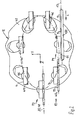
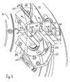
- the transfer device 2 of FIG. 1 is shown in detail.
- the transverse transverse direction 21, which can be seen in the transverse conveying direction Q in front of the transfer plane 20, is not occupied by a cigarette which has already been taken over to simplify the illustration.
- all recordings on the trough bottom of Fig. 3 apparent suction slots, is applied to the negative pressure to keep the cigarettes 91, 92 respectively in the recordings or release by switching off the suction air from the recordings.
- the drum body 31 and the takeover lever 22 are usually equipped with air ducts to operate the suction slots for simultaneous transfer and acceptance of the cigarettes 91, 92 in accordance with an air control.
- Such Saugluftabilityn and systems for holding and releasing cigarettes are common and will not be described here.
- the transfer conveyor 12 comprises a plurality of transfer elements 4 which circulate on an elliptical path.
- Such a transfer conveyor known per se receives cigarettes 9 from the horizontal transport plane 13.
- the cigarettes 9 are conveyed along a rail 130 in parallel paths 131, 132 in the longitudinal axial direction L.
- the transfer element 4 is shown in the lower in Fig. 2 position P1 at the transport plane 13 to illustrate the arrangement of cross conveyor 11 and transfer conveyor 12.
- Each transfer member 4 is connected by means of a nozzle piece 46 with a gear, not shown, to a housing 47 of the transfer conveyor 12.
- FIGS. 5A to 6B A specially adapted transfer element 4 is shown in FIGS. 5A to 6B. It has a U-shaped body 43. The U-legs form connected by U-web 45 parallel transfer arms 44. On one arm 44 along the same the outer transfer longitudinal receptacle 411 and on the other arm 44 in the same way, the inner transfer longitudinal receptacle 412 is formed.
- the longitudinal recordings 411, 412 extend itself in a plane which is defined as the feed-in level 40 of the transfer element 4.
- the elliptical guide of each transfer element 4 is such that it is lifted in Fig. 2 from the position P1 via an intermediate position P2 in the position P3, which corresponds to the position shown in Fig. 1 at the transfer plane 20.
- each element 4 remains in a horizontal and thus parallel position relative to the longitudinal transport plane 13.
- the cigarettes 9 conveyed at high speed in the double strand are transferred from the flat curved part into the strongly curved part of the elliptical path. In this way, a high-speed conversion of the cigarettes conveyed in the longitudinal direction L is achieved in a cross-axial direction Y.
- FIG. 1 shows a position in which the movable transverse mount 212 leads in the direction Y perpendicular to the transfer plane 20 with the path V in front of the delivery plane 40.
- the movement of the movable transverse receptacle 212 is specifically slowed down so much that at the time in Fig. 4B, in which the conveyor plane 40 in the takeover plane 20 passes, the speeds of the two transverse receptacles 211 and 212 are equal with respect to the speed of the feed plane 40, so there is no speed difference between the two transverse receptacles 211 and 212.
- This achieves the result that the cigarettes 91, 92 delivered in the transfer plane 20 by the transfer longitudinal receptacles 411, 412 are likewise delivered at considerable overspeeding to the transverse receptacles 211 and 212 receiving them.
- the speed of the feed plane 40 at the location of the takeover plane 20 is considerably greater than the same web speed of the two transverse receptacles 211, 212, expediently chosen to be 15% or more.
- a particular measure is that the receiving lever 22 is pivoted on approaching the receiving plane 20 such that the movable transverse receptacle 212 in the direction parallel to the Y direction, i. is brought to the transfer plane 20 vertical direction in a leading forward of the fixed cross-section 211 of the associated pair position.
- the movable transverse receptacle 212 is located at a distance Y3 in front of a moving plane EF, in which the fixed transverse receptacle 211 belonging to the pair lies and which is parallel to the transfer plane 20.
- the movable transverse receptacle 212 overhauls the associated fixed receptacle 211 in the Y direction before it is brought by deceleration in its takeover position in the transfer plane 20, the speeds of the two receptacles 211, 212 of a pair 21 at the time of acquisition in Relatively relate to the approaching transfer element 4 in particular even at relatively high conveying speed, namely at the lowest possible mechanical load of the lever 22 controlling curves and rollers.
- the drum body 31 can be readily operated at 650 rpm and more. Due to the inventive arrangement and articulation of the lever 22 its opening angle remains relatively small from the beginning of the opening at the lower drum peak to the maximum takeover opening position with an angle of less than 40 °.
- FIG. 5B The position of a recording lever 22 with recording 212 shown dash-dotted in FIG. 5B corresponds approximately to the position shown in FIG. 4A. With this position Similarly, a position shown in FIG. 6A at a somewhat later time corresponds to a plan view, while the plan view in FIG. 6B illustrates the situation at the receiving plane 20. It can be seen that each transfer element 4 is moved on its elliptical path in Fig. 2 in the direction parallel to the direction L and the coordinate direction Z on the lever 22. As is apparent in particular from FIGS.
- the lever pickup head 223 not only from above but also from the side passes between the transfer arms 44, it comes, according to not shown embodiment, for example, the U-web 45 by a in the conveying direction over the two arms 44 extending web element to replace, which leaves under such a bridge between the arms 44 and also above it sufficient free space.
- Each transfer element 4 is equipped with air intake openings known per se for holding the cigarettes 91, 92 in hollows of the receptacles 411, 412.
- a running along the U-extension channel for intake air is formed, which is open in the receiving troughs with suction slots.
- the centrally provided on the one arm 43 piece piece 46 forms both the suction port for the channel and the retaining piece for connection to the transmission of the transfer conveyor 12th
- each movable transverse receptacle 212 passes immediately after passing the lower apex of the drum body 31 when leaving the peripheral conveying surface 14 initially in positions in the Y direction behind the remaining in the pair 21 associated fixed transverse receptacle 211 with distances Y1 and Y2 decreasing remain. This achieves that each movable transverse receptacle 212 at the earliest possible time, on between the lower apex and the lateral apex of the drum body 31 relatively long track and relatively flat and thus emerges steadily from the transverse conveying surface 14 and is guided over this.
- each receiving lever 22 is controlled by means of a relative to the rotating drum body 31 stationary cam groove 321.
- each take-up lever 22 is pivotably mounted about an axis of rotation 220 by means of a pivot shaft 225 on an end wall of the drum body 31. With one end, the shaft 225 is passed through the wall of the drum body 31 and connected there to a roller lever 226 having a roller 227.
- the cam groove 321 is formed in a flange plate 32 which is fixed to a stationary, not shown, the drum body 31 rotatably supporting part.
Landscapes
- Manufacturing Of Cigar And Cigarette Tobacco (AREA)
- Specific Conveyance Elements (AREA)
Claims (17)
- Dispositif de transport (1) pour articles (9) en forme de tige de l'industrie de transformation du tabac, destiné à faire passer les articles (9) d'un transport suivant leur axe longitudinal dans un transport ultérieur transversal à leur axe, comportant un transporteur transversal (11) avec une surface de transport (14) curviligne s'étendant dans une direction de transport transversal (Q), qui présente des logements transversaux (141, 211, 212) disposés selon des écartements fixes (B) et recevant les articles en forme de tige (9), et avec un dispositif de prise (2) qui prend en charge des articles en forme de tige (9) approchés dans la direction (L) de leur axe longitudinal et qui comprend des paires de logements de prise en charge (21) en lesquelles les logements transversaux (141) sont divisés et qui présentent respectivement un logement transversal fixe (211) disposé de façon fixe au niveau de la surface de transport curviligne (14) et un logement transversal mobile (212) qu'il est possible d'amener hors de la surface de transport (14), dans une région libre au-dessus de cette dernière, le long d'une trajectoire commandée (23), et qui, pour la prise d'au moins un article en forme de tige (92), est déplaçable à l'encontre de la direction de transport transversal (Q), un plan de prise (20) étant déterminé, dans lequel respectivement une paire de logements de prise en charge (21) prend en charge l'article en forme de tige (9) approché dans la direction de l'axe longitudinal, avec le logement transversal mobile (212) amené dans sa position de prise, et la trajectoire commandée (23) étant telle que le logement transversal mobile (212) est ramené de sa position de prise dans sa position de transport au niveau de la surface de transport transversal (14), caractérisé en ce qu'au niveau de la surface de transport transversal curviligne (14), le logement transversal fixe (211) de chacune des paires de logements de prise en charge (21) est disposé en arrière du logement transversal mobile correspondant (212), dans la direction de transport transversal (Q), et le logement transversal mobile (212) est disposé et est déplaçable le long de sa trajectoire commandée (23) de façon telle qu'il soit amené, en allant vers sa position de prise dans le plan de prise (20), tel que vu dans la direction de courbure correspondant à la direction de transport transversal (Q), dans des positions devançant le logement transversal fixe (211) associé dans la paire, avec l'écartement en arc (B1, B2, B3, B4) par rapport au logement transversal fixe (211) qui diminue jusqu'à zéro.
- Dispositif selon la revendication 1, caractérisé en ce que le logement transversal mobile (212) de chaque paire de logements de prise en charge (21) est disposé et guidé le long de sa trajectoire (23) de façon telle qu'il parvienne, sur le trajet vers sa position de prise, tel que vu dans la direction (Y) perpendiculaire au plan de prise (20), dans des positions devançant le logement transversal fixe (211) associé dans la paire, à partir desquelles il est déplacé dans sa position de prise en réduisant l'écartement d'avance (Y3) dans la direction de visualisation verticale (Y).
- Dispositif selon la revendication 1 ou 2, caractérisé en ce que le logement transversal mobile (212) de chaque paire de logements de prise en charge (21) est disposé et guidé le long de sa trajectoire (23) de façon telle qu'il parvienne tout d'abord, sur le trajet vers sa position de prise, tel que vu dans la direction (Y) perpendiculaire au plan de prise (20), en quittant sa position sur la surface de transport (14), dans des positions (Y1, Y2) restant en arrière du logement transversal fixe (211).
- Dispositif selon l'une des revendications 1 à 3, caractérisé en ce que le logement transversal mobile (212) de chaque paire de logements de prise en charge (21) est disposé et guidé le long de sa trajectoire (23) de façon telle que, sur son trajet depuis la position de prise dans le plan de prise (20) jusqu'à la position de transport sur la surface de transport transversal (14), il parcoure un chemin qui est au moins légèrement inférieur au chemin depuis la position de transport jusqu'à la position de prise.
- Dispositif selon l'une des revendications 1 à 4, caractérisé en ce que chaque logement transversal mobile (212) fait partie intégrante d'un levier de réception respectif (22) maintenant à l'état rentré par pivotement le logement transversal mobile (212) au niveau de la surface de transport transversal (14), levier qui, vu dans la direction de transport transversal (Q), est, en arrière du logement transversal fixe (211) associé dans la paire, de préférence dans la zone entre les deux logements transversaux (211, 212) de la paire suivante (21) sur la surface de transport (14) dans la direction de transport transversal (Q), articulé à un corps de transport (31) déplaçant la surface de transport transversal (14), suite à quoi le levier de réception (22) bascule sur le trajet du logement transversal mobile (212) dans sa position de prise contre la direction de transport transversal (Q).
- Dispositif selon la revendication 5, caractérisé en ce que chaque levier de réception (22) est articulé à un certain niveau sous la surface de transport transversal (14).
- Dispositif selon la revendication 5 ou 6, caractérisé en ce que le bras pivotant efficace (220) de chaque levier de réception (22), dont la longueur de bras (H) est déterminée par le rayon de pivotement du logement transversal mobile (212), s'étend, à l'état rentré par pivotement, dans une position essentiellement plane par rapport à la surface de transport transversal (14).
- Dispositif selon l'une des revendications 5 à 7, caractérisé en ce que chaque levier de réception (22), dans la zone entre deux nervures (311) présentant les logements transversaux fixes (211), est articulé à proximité de la nervure arrière (311) dans la direction de transport transversal (Q).
- Dispositif selon l'une des revendications 5 à 8, caractérisé en ce que le levier de réception (22) est exécuté sous forme d'un bras angulaire avec une branche de bras libre (222) portant dans la zone de son extrémité libre le logement transversal mobile (212), laquelle branche de bras est orientée au moins dans des positions approchant le logement transversal mobile (212) au niveau du plan de prise (20) ainsi que dans la position de la prise essentiellement perpendiculairement à un plan avancé (EF) dans lequel repose le logement transversal fixe (211) associé dans la paire et qui est parallèle au plan de prise (20) ou coïncide avec celui-ci dans la position de prise.
- Dispositif selon l'une des revendications 5 à 9, caractérisé en ce que le levier de réception (22) porte une tête de réception (223) générant une force de retenue pour l'article à recevoir (9) et présentant au moins une partie en col (224), concave, formant le logement transversal mobile (212), qui est exécutée sur le côté de la tête de réception (223) orienté à l'opposé de la surface de transport transversal (14) et de l'extrémité libre du levier de réception (22).
- Dispositif selon l'une des revendications 1 à 10, caractérisé en ce que le transporteur transversal comprend un corps de révolution (31) à la surface périphérique duquel, laquelle forme la surface de transport transversal (14), sont disposés les logements transversaux fixes (211), de préférence aux extrémités libres de nervures cylindriques (311) dépassant radialement.
- Dispositif selon l'une des revendications 1 à 11, caractérisé en ce que les logements transversaux fixes et mobiles (211, 212) alternant au niveau de la surface de transport transversal (14) sont disposés selon le même écartement (B) et au moins sensiblement au même niveau.
- Dispositif selon l'une des revendications 1 à 12, caractérisé en ce que les logements transversaux (211, 212) de chaque paire de logements de prise en charge (21) présentent de grands angles de réception dans la zone d'au moins à peu près 90°.
- Dispositif selon l'une des revendications 1 à 13, caractérisé en ce que le plan de prise (20) est orienté, au moins à peu près, perpendiculairement à la surface de transport transversal (14), le transporteur transversal (11) comportant en particulier un corps de révolution (31) dont la surface périphérique forme la surface de transport transversal (14), et en ce que, de préférence, le plan de prise (20) se situe, dans chaque cas, sensiblement dans un plan horizontal.
- Dispositif selon l'une des revendications 1 à 14, caractérisé en ce que le transporteur transversal (11) comprend un corps de révolution (32) dont la surface périphérique forme la surface de transport transversal (14), et en ce que le logement transversal mobile (212) de chaque paire de logements (21) est disposé et guidé le long de sa trajectoire (23) de façon telle que le trajet depuis qu'il quitte la surface de transport (14) jusqu'à ce qu'il soit dans la position de prise, se situe dans une plage de rotation angulaire du corps de révolution (31) de 90°, le logement transversal mobile (212) étant soulevé de la surface de transport (14) de préférence dans la zone du point le plus bas du corps de révolution (31) et étant guidé dans le plan de prise horizontal (20) au niveau d'un point le plus latéral du corps de révolution (32).
- Dispositif selon l'une des revendications 1 à 15, caractérisé en ce que le logement transversal mobile (212) de chaque paire de logements de prise en charge (21) est disposé et guidé le long de sa trajectoire (23) de façon telle que le trajet depuis qu'il quitte le plan de prise (20) jusqu'à ce qu'il soit dans la position de transport au niveau de la surface de transport transversal (14), se situe dans une plage de rotation angulaire du corps de révolution (31) de 90°, le logement mobile (212) parvenant dans la position de transport au niveau de la surface de transport transversal (14), de préférence, dans la zone du point le plus haut du corps de révolution (31).
- Dispositif selon l'une des revendications 1 à 16, caractérisé en ce que le dispositif de transport (1) comprend un transporteur de transfert (12) ayant plusieurs paires de logements de transfert (41) formées par des logements longitudinaux (411, 412), qui correspondent par paires avec les logements transversaux de prise en charge (211, 212), l'agencement étant tel, que chaque logement de transfert (411, 412) reçoit sur des trajectoires parallèles (132, 133) des articles en forme de tige (9) amenés suivant leur axe longitudinal et, en conservant leur positionnement mutuel parallèle, les transporte dans un plan de déplacement d'avance (40) dans la direction transversale à l'axe, dans le plan de prise (20), le logement transversal mobile (212) de chacune des paires de logements de prise en charge (21) étant disposé et guidé le long de sa trajectoire (23) de façon telle que, vu dans la direction de transport transversal (Q), il parvienne dans des positions devançant le plan d'avance (40) de la paire de logements de transfert correspondante (41), depuis lesquelles il est déplacé dans sa position de prise dans le plan de prise (20) selon un écartement d'avance (V) qui diminue jusqu'à zéro.
Priority Applications (3)
| Application Number | Priority Date | Filing Date | Title |
|---|---|---|---|
| EP03090198A EP1493338B1 (fr) | 2003-07-04 | 2003-07-04 | Appareil de transport pour transférer des articles en forme de tige de l'industrie du tabac, du transport de la direction longitudinale vers une direction transversale |
| AT03090198T ATE345704T1 (de) | 2003-07-04 | 2003-07-04 | Fördervorrichtung zum überführen von stabförmigen artikelen der tabak verarbeitenden industrie aus längsaxialer förderung in queraxiale weiterförderung |
| DE50305750T DE50305750D1 (de) | 2003-07-04 | 2003-07-04 | Fördervorrichtung zum Überführen von stabförmigen Artikelen der Tabak verarbeitenden Industrie aus längsaxialer Förderung in queraxiale Weiterförderung |
Applications Claiming Priority (1)
| Application Number | Priority Date | Filing Date | Title |
|---|---|---|---|
| EP03090198A EP1493338B1 (fr) | 2003-07-04 | 2003-07-04 | Appareil de transport pour transférer des articles en forme de tige de l'industrie du tabac, du transport de la direction longitudinale vers une direction transversale |
Publications (2)
| Publication Number | Publication Date |
|---|---|
| EP1493338A1 EP1493338A1 (fr) | 2005-01-05 |
| EP1493338B1 true EP1493338B1 (fr) | 2006-11-22 |
Family
ID=33427163
Family Applications (1)
| Application Number | Title | Priority Date | Filing Date |
|---|---|---|---|
| EP03090198A Expired - Lifetime EP1493338B1 (fr) | 2003-07-04 | 2003-07-04 | Appareil de transport pour transférer des articles en forme de tige de l'industrie du tabac, du transport de la direction longitudinale vers une direction transversale |
Country Status (3)
| Country | Link |
|---|---|
| EP (1) | EP1493338B1 (fr) |
| AT (1) | ATE345704T1 (fr) |
| DE (1) | DE50305750D1 (fr) |
Cited By (3)
| Publication number | Priority date | Publication date | Assignee | Title |
|---|---|---|---|---|
| CN102551197A (zh) * | 2010-12-03 | 2012-07-11 | 豪尼机械制造股份公司 | 用于输送烟草加工业的棒形制品的输送装置 |
| DE102011006121A1 (de) | 2011-03-25 | 2012-09-27 | Hauni Maschinenbau Ag | Inbetriebnahme einer Maschine der Tabak verarbeitenden Industrie |
| CN103315394A (zh) * | 2012-03-22 | 2013-09-25 | 吉地股份公司 | 用于传递过滤嘴或香烟杆的装置 |
Families Citing this family (11)
| Publication number | Priority date | Publication date | Assignee | Title |
|---|---|---|---|---|
| DE102005033504A1 (de) * | 2005-07-14 | 2007-01-18 | Hauni Maschinenbau Ag | Vorrichtung zum Transport von stabförmigen Artikeln der tabakverarbeitenden Industrie |
| DE102010001362A1 (de) * | 2010-01-29 | 2011-08-04 | Hauni Maschinenbau AG, 21033 | Fördertrommel der Tabak verarbeitenden Industrie |
| DE102011009384A1 (de) * | 2011-01-25 | 2012-07-26 | Hauni Maschinenbau Ag | Fördervorrichtung für stabförmige Produkte der Tabak verarbeitenden Industrie |
| DE102011103822A1 (de) * | 2011-06-01 | 2012-12-06 | Hauni Maschinenbau Ag | Transporttrommel für Produkte der Tabak verarbeitenden Industrie |
| DE102013104708B4 (de) * | 2013-05-07 | 2016-05-19 | Mts Tobacco S.A. | Vorrichtung zum Übergeben von stabförmigen Rauchartikeln |
| DE102013209181B3 (de) * | 2013-05-17 | 2014-04-03 | Hauni Maschinenbau Ag | Fördervorrichtung für stabförmige Produkte der Tabak verarbeitenden Industrie |
| DE102015200803B4 (de) * | 2015-01-20 | 2016-09-01 | Hauni Maschinenbau Gmbh | Fördertrommel der Tabak verarbeitenden Industrie |
| GB201609409D0 (en) | 2016-05-27 | 2016-07-13 | British American Tobacco Co | Apparatus and method for manufacturing tobacco industry products |
| GB201609407D0 (en) | 2016-05-27 | 2016-07-13 | British American Tobacco Co | Apparatus and method for manufacturing tobacco industry products |
| PL239524B1 (pl) | 2018-09-10 | 2021-12-13 | Int Tobacco Machinery Poland Spolka Z Ograniczona Odpowiedzialnoscia | Urządzenie do transferowania artykułów prętopodobnych przemysłu tytoniowego |
| CN110466822A (zh) * | 2019-08-15 | 2019-11-19 | 河南中烟工业有限责任公司 | 一种烟支转塔装置 |
Family Cites Families (5)
| Publication number | Priority date | Publication date | Assignee | Title |
|---|---|---|---|---|
| DE643796C (de) * | 1935-08-11 | 1937-04-27 | Koelner Werkzeugmaschinenfabri | Vorrichtung zum Abbremsen der aus einer Strangzigarettenmaschine austretenden Zigaretten |
| IT1222773B (it) * | 1986-10-30 | 1990-09-12 | Hauni Werke Koerber & Co Kg | Dispositivo trasportatore per trasportare articolare a bastoncino dell'industria di lavorazione del tabacco |
| DE4121201A1 (de) * | 1991-06-27 | 1993-01-07 | Decoufle Sarl | Foerdervorrichtung zum ueberfuehren von stabfoermigen artikeln |
| DE4129672C2 (de) * | 1991-09-06 | 2002-04-11 | Hauni Werke Koerber & Co Kg | Fördervorrichtung zum Fördern stabförmiger Artikel der tabakverarbeitenden Industrie |
| ITBO20000446A1 (it) * | 2000-07-21 | 2002-01-21 | Gd Spa | Unita' e metodo di trasferimento di spezzoni di sigaretta . |
-
2003
- 2003-07-04 EP EP03090198A patent/EP1493338B1/fr not_active Expired - Lifetime
- 2003-07-04 AT AT03090198T patent/ATE345704T1/de not_active IP Right Cessation
- 2003-07-04 DE DE50305750T patent/DE50305750D1/de not_active Expired - Fee Related
Cited By (4)
| Publication number | Priority date | Publication date | Assignee | Title |
|---|---|---|---|---|
| CN102551197A (zh) * | 2010-12-03 | 2012-07-11 | 豪尼机械制造股份公司 | 用于输送烟草加工业的棒形制品的输送装置 |
| DE102011006121A1 (de) | 2011-03-25 | 2012-09-27 | Hauni Maschinenbau Ag | Inbetriebnahme einer Maschine der Tabak verarbeitenden Industrie |
| WO2012130401A1 (fr) | 2011-03-25 | 2012-10-04 | Hauni Maschinenbau Ag | Mise en service d'une machine de l'industrie de transformation du tabac |
| CN103315394A (zh) * | 2012-03-22 | 2013-09-25 | 吉地股份公司 | 用于传递过滤嘴或香烟杆的装置 |
Also Published As
| Publication number | Publication date |
|---|---|
| EP1493338A1 (fr) | 2005-01-05 |
| DE50305750D1 (de) | 2007-01-04 |
| ATE345704T1 (de) | 2006-12-15 |
Similar Documents
| Publication | Publication Date | Title |
|---|---|---|
| DE4129672C2 (de) | Fördervorrichtung zum Fördern stabförmiger Artikel der tabakverarbeitenden Industrie | |
| AT406668B (de) | Vorrichtung zur übernahme und beförderung von gegenständen | |
| EP1287753B1 (fr) | Dispositif et méthode de transfert d'articles de l'industrie du tabac | |
| EP1493338A1 (fr) | Appareil de transport et élément de transfert pour transférer des articles en forme de tige de l'industrie du tabac, du transport de la direction longitudinale vers une direction transversale | |
| EP1994838A1 (fr) | Tambour de transport | |
| DE3735006A1 (de) | Foerdervorrichtung zum foerdern stabfoermiger artikel der tabakverarbeitenden industrie | |
| DE102010002132A1 (de) | Tabakstrangmaschine zur Herstellung von Tabakstäben, Filteransetzmaschine zum Verbinden von Filtern mit Tabakstäben sowie Zigarettenherstellungsmaschine | |
| DE19847152A1 (de) | Anordnung zum Überführen von ovalen Zigaretten aus einer axialen in eine queraxiale Förderbahn | |
| EP2478782B1 (fr) | Dispositif de transport pour produits en forme de tige de l'industrie de traitement du tabac | |
| EP3248477B2 (fr) | Dispositif d'insertion et machine de fabrication de tiges de l'industrie de traitement du tabac | |
| EP0718223B1 (fr) | Dispositif de transfert pour marchandises, notamment pour boítes | |
| DE2513867C3 (de) | Hochleistungs-Zigarettenstrangmaschine mit einem saugradförmigen Tabakstrang-Bandförderer | |
| EP3069619B1 (fr) | Dispositif destine a tourner des produits en forme de tige de l'industrie de traitement du tabac autour d'un axe transversal dispose perpendiculairement a un axe longitudinal des produits | |
| DE2308349A1 (de) | Vorrichtung zur bildung von paaren koaxial zueinander ausgerichteter, voneinander axial distanzierter zigaretten od. dgl | |
| EP1503909B1 (fr) | Station de mise sous enveloppe pour des systemes de traitement de courrier | |
| DE2205659C3 (de) | Vorrichtung zum Fördern von in Längsrichtung hintereinanderliegend zu einer Einspeisezone angelieferten stabförmigen Gegenständen, insbesondere Zigaretten | |
| DE102013104708B4 (de) | Vorrichtung zum Übergeben von stabförmigen Rauchartikeln | |
| EP4175495B1 (fr) | Dispositif de transfert et procédé pour transférer des articles en forme de tige depuis un dispositif de formation de boudin à un dispositif de tambour | |
| DE20200794U1 (de) | Vorrichtung zum Verteilen von Behältern | |
| EP3338567A1 (fr) | Dispositif de transport rotatif destiné au transport d'articles de l'industrie du traitement du tabac | |
| CH719848A1 (de) | Förderanlage mit einer Vorrichtung zum Lenken von liegend geförderten Fördergütern. | |
| DE2326181A1 (de) | Foerdereinrichtung zum foerdern stabfoermiger artikel | |
| DE102016111818B4 (de) | Positionierung von stabförmigen Artikeln der Tabak verarbeitenden Industrie in eine Einlegevorrichtung | |
| DE69900922T2 (de) | Vorrichtung zum aufeinanderfolgenden Zuführen von Zuschnitten, Etiketten oder dergleichen | |
| EP2568832A1 (fr) | Dispositif et procédé pour le transfert d'articles en forme de tiges de l'industrie du tabac d'un premier élément de transport sur un deuxième élément de transport |
Legal Events
| Date | Code | Title | Description |
|---|---|---|---|
| PUAI | Public reference made under article 153(3) epc to a published international application that has entered the european phase |
Free format text: ORIGINAL CODE: 0009012 |
|
| AK | Designated contracting states |
Kind code of ref document: A1 Designated state(s): AT BE BG CH CY CZ DE DK EE ES FI FR GB GR HU IE IT LI LU MC NL PT RO SE SI SK TR |
|
| AX | Request for extension of the european patent |
Extension state: AL LT LV MK |
|
| 17P | Request for examination filed |
Effective date: 20050629 |
|
| AKX | Designation fees paid |
Designated state(s): AT BE BG CH CY CZ DE DK EE ES FI FR GB GR HU IE IT LI LU MC NL PT RO SE SI SK TR |
|
| GRAP | Despatch of communication of intention to grant a patent |
Free format text: ORIGINAL CODE: EPIDOSNIGR1 |
|
| RTI1 | Title (correction) |
Free format text: TRANSPORT DEVICE FOR TRANSFERRING RODLIKE ARTICLES OF THE TOBACCO PROCESSING INDUSTRY FROM TRANSPORT IN THE DIRECTION OF THE LONGITUDINAL AXIS TO THE TRANSVERSE DIRECTION |
|
| GRAS | Grant fee paid |
Free format text: ORIGINAL CODE: EPIDOSNIGR3 |
|
| GRAA | (expected) grant |
Free format text: ORIGINAL CODE: 0009210 |
|
| AK | Designated contracting states |
Kind code of ref document: B1 Designated state(s): AT BE BG CH CY CZ DE DK EE ES FI FR GB GR HU IE IT LI LU MC NL PT RO SE SI SK TR |
|
| PG25 | Lapsed in a contracting state [announced via postgrant information from national office to epo] |
Ref country code: IT Free format text: LAPSE BECAUSE OF FAILURE TO SUBMIT A TRANSLATION OF THE DESCRIPTION OR TO PAY THE FEE WITHIN THE PRESCRIBED TIME-LIMIT;WARNING: LAPSES OF ITALIAN PATENTS WITH EFFECTIVE DATE BEFORE 2007 MAY HAVE OCCURRED AT ANY TIME BEFORE 2007. THE CORRECT EFFECTIVE DATE MAY BE DIFFERENT FROM THE ONE RECORDED. Effective date: 20061122 Ref country code: CZ Free format text: LAPSE BECAUSE OF FAILURE TO SUBMIT A TRANSLATION OF THE DESCRIPTION OR TO PAY THE FEE WITHIN THE PRESCRIBED TIME-LIMIT Effective date: 20061122 Ref country code: IE Free format text: LAPSE BECAUSE OF FAILURE TO SUBMIT A TRANSLATION OF THE DESCRIPTION OR TO PAY THE FEE WITHIN THE PRESCRIBED TIME-LIMIT Effective date: 20061122 Ref country code: FI Free format text: LAPSE BECAUSE OF FAILURE TO SUBMIT A TRANSLATION OF THE DESCRIPTION OR TO PAY THE FEE WITHIN THE PRESCRIBED TIME-LIMIT Effective date: 20061122 Ref country code: SK Free format text: LAPSE BECAUSE OF FAILURE TO SUBMIT A TRANSLATION OF THE DESCRIPTION OR TO PAY THE FEE WITHIN THE PRESCRIBED TIME-LIMIT Effective date: 20061122 Ref country code: RO Free format text: LAPSE BECAUSE OF FAILURE TO SUBMIT A TRANSLATION OF THE DESCRIPTION OR TO PAY THE FEE WITHIN THE PRESCRIBED TIME-LIMIT Effective date: 20061122 Ref country code: NL Free format text: LAPSE BECAUSE OF FAILURE TO SUBMIT A TRANSLATION OF THE DESCRIPTION OR TO PAY THE FEE WITHIN THE PRESCRIBED TIME-LIMIT Effective date: 20061122 Ref country code: SI Free format text: LAPSE BECAUSE OF FAILURE TO SUBMIT A TRANSLATION OF THE DESCRIPTION OR TO PAY THE FEE WITHIN THE PRESCRIBED TIME-LIMIT Effective date: 20061122 |
|
| REG | Reference to a national code |
Ref country code: GB Ref legal event code: FG4D Free format text: NOT ENGLISH |
|
| REG | Reference to a national code |
Ref country code: CH Ref legal event code: EP |
|
| REG | Reference to a national code |
Ref country code: IE Ref legal event code: FG4D Free format text: LANGUAGE OF EP DOCUMENT: GERMAN |
|
| REF | Corresponds to: |
Ref document number: 50305750 Country of ref document: DE Date of ref document: 20070104 Kind code of ref document: P |
|
| PG25 | Lapsed in a contracting state [announced via postgrant information from national office to epo] |
Ref country code: SE Free format text: LAPSE BECAUSE OF FAILURE TO SUBMIT A TRANSLATION OF THE DESCRIPTION OR TO PAY THE FEE WITHIN THE PRESCRIBED TIME-LIMIT Effective date: 20070222 Ref country code: DK Free format text: LAPSE BECAUSE OF FAILURE TO SUBMIT A TRANSLATION OF THE DESCRIPTION OR TO PAY THE FEE WITHIN THE PRESCRIBED TIME-LIMIT Effective date: 20070222 Ref country code: BG Free format text: LAPSE BECAUSE OF FAILURE TO SUBMIT A TRANSLATION OF THE DESCRIPTION OR TO PAY THE FEE WITHIN THE PRESCRIBED TIME-LIMIT Effective date: 20070222 |
|
| PG25 | Lapsed in a contracting state [announced via postgrant information from national office to epo] |
Ref country code: ES Free format text: LAPSE BECAUSE OF FAILURE TO SUBMIT A TRANSLATION OF THE DESCRIPTION OR TO PAY THE FEE WITHIN THE PRESCRIBED TIME-LIMIT Effective date: 20070305 |
|
| PG25 | Lapsed in a contracting state [announced via postgrant information from national office to epo] |
Ref country code: PT Free format text: LAPSE BECAUSE OF FAILURE TO SUBMIT A TRANSLATION OF THE DESCRIPTION OR TO PAY THE FEE WITHIN THE PRESCRIBED TIME-LIMIT Effective date: 20070423 |
|
| NLV1 | Nl: lapsed or annulled due to failure to fulfill the requirements of art. 29p and 29m of the patents act | ||
| GBV | Gb: ep patent (uk) treated as always having been void in accordance with gb section 77(7)/1977 [no translation filed] |
Effective date: 20061122 |
|
| REG | Reference to a national code |
Ref country code: IE Ref legal event code: FD4D |
|
| EN | Fr: translation not filed | ||
| PLBE | No opposition filed within time limit |
Free format text: ORIGINAL CODE: 0009261 |
|
| STAA | Information on the status of an ep patent application or granted ep patent |
Free format text: STATUS: NO OPPOSITION FILED WITHIN TIME LIMIT |
|
| 26N | No opposition filed |
Effective date: 20070823 |
|
| PG25 | Lapsed in a contracting state [announced via postgrant information from national office to epo] |
Ref country code: GB Free format text: LAPSE BECAUSE OF FAILURE TO SUBMIT A TRANSLATION OF THE DESCRIPTION OR TO PAY THE FEE WITHIN THE PRESCRIBED TIME-LIMIT Effective date: 20061122 |
|
| BERE | Be: lapsed |
Owner name: HAUNI MASCHINENBAU A.G. Effective date: 20070731 |
|
| REG | Reference to a national code |
Ref country code: CH Ref legal event code: PL |
|
| PG25 | Lapsed in a contracting state [announced via postgrant information from national office to epo] |
Ref country code: LI Free format text: LAPSE BECAUSE OF NON-PAYMENT OF DUE FEES Effective date: 20070731 Ref country code: GR Free format text: LAPSE BECAUSE OF FAILURE TO SUBMIT A TRANSLATION OF THE DESCRIPTION OR TO PAY THE FEE WITHIN THE PRESCRIBED TIME-LIMIT Effective date: 20070223 Ref country code: MC Free format text: LAPSE BECAUSE OF NON-PAYMENT OF DUE FEES Effective date: 20070731 Ref country code: CH Free format text: LAPSE BECAUSE OF NON-PAYMENT OF DUE FEES Effective date: 20070731 Ref country code: FR Free format text: LAPSE BECAUSE OF FAILURE TO SUBMIT A TRANSLATION OF THE DESCRIPTION OR TO PAY THE FEE WITHIN THE PRESCRIBED TIME-LIMIT Effective date: 20070713 |
|
| PG25 | Lapsed in a contracting state [announced via postgrant information from national office to epo] |
Ref country code: BE Free format text: LAPSE BECAUSE OF NON-PAYMENT OF DUE FEES Effective date: 20070731 |
|
| PG25 | Lapsed in a contracting state [announced via postgrant information from national office to epo] |
Ref country code: FR Free format text: LAPSE BECAUSE OF FAILURE TO SUBMIT A TRANSLATION OF THE DESCRIPTION OR TO PAY THE FEE WITHIN THE PRESCRIBED TIME-LIMIT Effective date: 20061122 Ref country code: AT Free format text: LAPSE BECAUSE OF NON-PAYMENT OF DUE FEES Effective date: 20070704 |
|
| PG25 | Lapsed in a contracting state [announced via postgrant information from national office to epo] |
Ref country code: EE Free format text: LAPSE BECAUSE OF FAILURE TO SUBMIT A TRANSLATION OF THE DESCRIPTION OR TO PAY THE FEE WITHIN THE PRESCRIBED TIME-LIMIT Effective date: 20061122 |
|
| PG25 | Lapsed in a contracting state [announced via postgrant information from national office to epo] |
Ref country code: LU Free format text: LAPSE BECAUSE OF NON-PAYMENT OF DUE FEES Effective date: 20070704 Ref country code: CY Free format text: LAPSE BECAUSE OF FAILURE TO SUBMIT A TRANSLATION OF THE DESCRIPTION OR TO PAY THE FEE WITHIN THE PRESCRIBED TIME-LIMIT Effective date: 20061122 |
|
| PG25 | Lapsed in a contracting state [announced via postgrant information from national office to epo] |
Ref country code: HU Free format text: LAPSE BECAUSE OF FAILURE TO SUBMIT A TRANSLATION OF THE DESCRIPTION OR TO PAY THE FEE WITHIN THE PRESCRIBED TIME-LIMIT Effective date: 20070523 Ref country code: TR Free format text: LAPSE BECAUSE OF FAILURE TO SUBMIT A TRANSLATION OF THE DESCRIPTION OR TO PAY THE FEE WITHIN THE PRESCRIBED TIME-LIMIT Effective date: 20061122 |
|
| PGFP | Annual fee paid to national office [announced via postgrant information from national office to epo] |
Ref country code: DE Payment date: 20090731 Year of fee payment: 7 |
|
| PGFP | Annual fee paid to national office [announced via postgrant information from national office to epo] |
Ref country code: IT Payment date: 20090723 Year of fee payment: 7 |
|
| PG25 | Lapsed in a contracting state [announced via postgrant information from national office to epo] |
Ref country code: DE Free format text: LAPSE BECAUSE OF NON-PAYMENT OF DUE FEES Effective date: 20110201 |
|
| REG | Reference to a national code |
Ref country code: DE Ref legal event code: R119 Ref document number: 50305750 Country of ref document: DE Effective date: 20110201 |
|
| PG25 | Lapsed in a contracting state [announced via postgrant information from national office to epo] |
Ref country code: IT Free format text: LAPSE BECAUSE OF NON-PAYMENT OF DUE FEES Effective date: 20100704 |