EP1493390A1 - Chirurgischer, verformbarer Schaft - Google Patents
Chirurgischer, verformbarer Schaft Download PDFInfo
- Publication number
- EP1493390A1 EP1493390A1 EP04253850A EP04253850A EP1493390A1 EP 1493390 A1 EP1493390 A1 EP 1493390A1 EP 04253850 A EP04253850 A EP 04253850A EP 04253850 A EP04253850 A EP 04253850A EP 1493390 A1 EP1493390 A1 EP 1493390A1
- Authority
- EP
- European Patent Office
- Prior art keywords
- cam
- malleable shaft
- malleable
- shaft device
- stage
- Prior art date
- Legal status (The legal status is an assumption and is not a legal conclusion. Google has not performed a legal analysis and makes no representation as to the accuracy of the status listed.)
- Withdrawn
Links
- 239000000835 fiber Substances 0.000 claims abstract description 48
- 230000008901 benefit Effects 0.000 claims abstract description 30
- 230000007704 transition Effects 0.000 claims abstract description 24
- 238000006073 displacement reaction Methods 0.000 claims abstract description 20
- 238000001356 surgical procedure Methods 0.000 claims abstract description 7
- 238000000418 atomic force spectrum Methods 0.000 claims abstract description 6
- 210000000245 forearm Anatomy 0.000 claims description 12
- 238000007514 turning Methods 0.000 claims description 12
- 239000003381 stabilizer Substances 0.000 description 6
- 238000000034 method Methods 0.000 description 4
- 230000000295 complement effect Effects 0.000 description 3
- 230000004913 activation Effects 0.000 description 2
- 238000013459 approach Methods 0.000 description 2
- 238000004519 manufacturing process Methods 0.000 description 2
- 230000007246 mechanism Effects 0.000 description 2
- 230000001131 transforming effect Effects 0.000 description 2
- 230000009471 action Effects 0.000 description 1
- 230000004075 alteration Effects 0.000 description 1
- 230000003872 anastomosis Effects 0.000 description 1
- 238000010009 beating Methods 0.000 description 1
- 230000008859 change Effects 0.000 description 1
- 210000004351 coronary vessel Anatomy 0.000 description 1
- 238000005516 engineering process Methods 0.000 description 1
- 230000006872 improvement Effects 0.000 description 1
- 230000002452 interceptive effect Effects 0.000 description 1
- 238000003754 machining Methods 0.000 description 1
- 239000000463 material Substances 0.000 description 1
- 239000002184 metal Substances 0.000 description 1
- 230000004048 modification Effects 0.000 description 1
- 238000012986 modification Methods 0.000 description 1
- 210000004165 myocardium Anatomy 0.000 description 1
- 230000008569 process Effects 0.000 description 1
- 230000006641 stabilisation Effects 0.000 description 1
- 238000011105 stabilization Methods 0.000 description 1
- 210000000115 thoracic cavity Anatomy 0.000 description 1
- 230000009466 transformation Effects 0.000 description 1
Images






Classifications
-
- A—HUMAN NECESSITIES
- A61—MEDICAL OR VETERINARY SCIENCE; HYGIENE
- A61B—DIAGNOSIS; SURGERY; IDENTIFICATION
- A61B17/00—Surgical instruments, devices or methods
- A61B17/02—Surgical instruments, devices or methods for holding wounds open, e.g. retractors; Tractors
-
- A—HUMAN NECESSITIES
- A61—MEDICAL OR VETERINARY SCIENCE; HYGIENE
- A61B—DIAGNOSIS; SURGERY; IDENTIFICATION
- A61B17/00—Surgical instruments, devices or methods
- A61B17/02—Surgical instruments, devices or methods for holding wounds open, e.g. retractors; Tractors
- A61B2017/0237—Surgical instruments, devices or methods for holding wounds open, e.g. retractors; Tractors for heart surgery
- A61B2017/0243—Surgical instruments, devices or methods for holding wounds open, e.g. retractors; Tractors for heart surgery for immobilizing local areas of the heart, e.g. while it beats
-
- A—HUMAN NECESSITIES
- A61—MEDICAL OR VETERINARY SCIENCE; HYGIENE
- A61B—DIAGNOSIS; SURGERY; IDENTIFICATION
- A61B17/00—Surgical instruments, devices or methods
- A61B17/28—Surgical forceps
- A61B17/29—Forceps for use in minimally invasive surgery
- A61B17/2909—Handles
- A61B2017/2912—Handles transmission of forces to actuating rod or piston
- A61B2017/2913—Handles transmission of forces to actuating rod or piston cams or guiding means
-
- A—HUMAN NECESSITIES
- A61—MEDICAL OR VETERINARY SCIENCE; HYGIENE
- A61B—DIAGNOSIS; SURGERY; IDENTIFICATION
- A61B17/00—Surgical instruments, devices or methods
- A61B17/28—Surgical forceps
- A61B17/29—Forceps for use in minimally invasive surgery
- A61B17/2909—Handles
- A61B2017/2912—Handles transmission of forces to actuating rod or piston
- A61B2017/2913—Handles transmission of forces to actuating rod or piston cams or guiding means
- A61B2017/2915—Handles transmission of forces to actuating rod or piston cams or guiding means arcuate shaped guiding means
-
- A—HUMAN NECESSITIES
- A61—MEDICAL OR VETERINARY SCIENCE; HYGIENE
- A61B—DIAGNOSIS; SURGERY; IDENTIFICATION
- A61B17/00—Surgical instruments, devices or methods
- A61B17/28—Surgical forceps
- A61B17/29—Forceps for use in minimally invasive surgery
- A61B17/2909—Handles
- A61B2017/2912—Handles transmission of forces to actuating rod or piston
- A61B2017/2913—Handles transmission of forces to actuating rod or piston cams or guiding means
- A61B2017/2916—Handles transmission of forces to actuating rod or piston cams or guiding means pins in guiding slots
-
- A—HUMAN NECESSITIES
- A61—MEDICAL OR VETERINARY SCIENCE; HYGIENE
- A61B—DIAGNOSIS; SURGERY; IDENTIFICATION
- A61B17/00—Surgical instruments, devices or methods
- A61B17/28—Surgical forceps
- A61B17/29—Forceps for use in minimally invasive surgery
- A61B17/2909—Handles
- A61B2017/2912—Handles transmission of forces to actuating rod or piston
- A61B2017/2913—Handles transmission of forces to actuating rod or piston cams or guiding means
- A61B2017/2917—Handles transmission of forces to actuating rod or piston cams or guiding means with flexible part
-
- Y—GENERAL TAGGING OF NEW TECHNOLOGICAL DEVELOPMENTS; GENERAL TAGGING OF CROSS-SECTIONAL TECHNOLOGIES SPANNING OVER SEVERAL SECTIONS OF THE IPC; TECHNICAL SUBJECTS COVERED BY FORMER USPC CROSS-REFERENCE ART COLLECTIONS [XRACs] AND DIGESTS
- Y10—TECHNICAL SUBJECTS COVERED BY FORMER USPC
- Y10T—TECHNICAL SUBJECTS COVERED BY FORMER US CLASSIFICATION
- Y10T403/00—Joints and connections
- Y10T403/57—Distinct end coupler
- Y10T403/5793—Distinct end coupler including member wedging or camming means
Definitions
- the invention relates to the field of tension-stiffening devices and surgical instrumentation. More specifically, it relates to a variable-pitch cam mechanism for use in a malleable-shaft surgical retractor, particularly those that have a fiber running through their length and stiffen upon the tensioning of that fiber.
- malleable shaft stabilization devices are known in the art. Particularly in Coronary Artery Bypass Graft (CABG) procedures, such instruments are used to stabilize the surface of the beating heart muscle at the site where the anastomosis will be formed.
- the instruments will have a malleable shaft of a certain length, with a stabilizer foot at a distal end.
- the shaft can be positioned as required, then a lead screw at a proximal end is turned by some manner of handle.
- the turning of the lead screw applies tension to a fiber, such as a metal wire or braided cable.
- the tensioning of the cable compresses the malleable shaft, and secures it rigidly into position.
- the position of the stabilizer positioned on an end of the malleable shaft may drift on the surface of the heart.
- a malleable shaft device for use in surgical procedures, having a tension fiber therein, whereby the malleable shaft transitions from a malleable state to a rigid state when a force is applied to the tension fiber, has a variable-pitch cam operatively connected to the tension fiber, and a lever operatively connected to the variable pitch cam for applying force.
- the mechanical advantage of the cam changes with displacement to accommodate increasing load, and to increase the rate of travel while loads are light.
- the force profile may provide for a constant input force to accomplish the full travel of the cam.
- the force profile can provide for the full travel of the cam in a limited range of motion, for example one full turn, one-half turn, or within the range of motion of the longitudinal turning of a human forearm for some portion of the population.
- the cam may be transformed into any of several actuation modalities by transforming the cam profile, for example from a cylindrical cam to a linear cam.
- a plural-stage device that has varying mechanical advantages among the plural stages.
- Fig. 1 illustrates a malleable shaft surgical device including a variable pitch cam according to the present invention
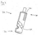
- Fig. 2 illustrates a first embodiment of the variable pitch cam according to the present invention
- Figs. 3A through 3C illustrate a second embodiment of the present invention in three mutually orthogonal views
- Fig. 4 illustrates yet another embodiment of the present invention having a linear, rather than rotating cam
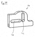
- Figs. 4A and 4B illustrate alternate configurations of the linear cam plate for use with the embodiment of Fig. 4;
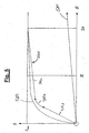
- Fig. 5 illustrates various displacement profiles for cams used in tension devices, including two according to the present invention
- Fig. 6 illustrates a two-stage embodiment of the present invention in an exploded assembly view
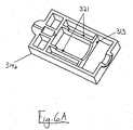
- Fig. 6A shows an underside of the upper portion of the embodiment illustrated in Fig. 6;
- Fig. 7 illustrates the dimensions of rotation of the human forearm taken into account in the design and practice of the present invention.
- a malleable shaft device 10 In this case, the device is attached to a rib retractor 12, also commonly used in thoracic surgeries.
- the malleable shaft device 10 has a base 14, which can include a slot 16 for attachment to another device such as retractor 12. Extending distally from the base 14 is a malleable shaft 18.
- the malleable shaft 18 will typically have an operative tool such as a stabilizer foot 19, alternately a retractor blade, or other attachment at a distal end thereof.
- a tension fiber (not shown) that may be a single- or multi-strand wire, braided cable, or other suitable element and material.
- the variable-pitch cam 22 is operatively connected to the tension fiber.
- a cylindrical cam 22 according to a first embodiment of the present invention.
- the cylindrical cam 22 has a cam slot 24 formed along its circumference.
- Cam 22 may also include a keyway 26 at a proximal end 30.
- the keyway can be provided for the attachment of a torque-applying element, such as handle 20 (See, Fig. I).
- the tension fiber (not shown) is operatively connected at a distal end 32 of the cam 22.
- the goal is to produce a constant actuating force regardless of the tension required.
- a further object of the present invention is to accomplish the full travel, S max , of the tension fiber in a much smaller angular displacement than currently required by the prior art.
- the full travel of the tension fiber is accomplished in less that one full turn of the cam (2 ⁇ ). More preferably, the cam will accomplish the full travel of the tension fiber in less than one half turn ( ⁇ ). Alternately, the cam will accomplish the full travel of the tension fiber within the typical range of motion of the longitudinal turning of a human forearm.
- a second embodiment 110 ofthe present invention is shown in three orthogonal views, respectively.
- the activation lever 34 is operatively connected along the length of cam 22, though it may also be positioned at a proximal end thereof, similar to the first embodiment, supra .
- This embodiment is particularly advantageous when used in combination with the cam profile described above, wherein the full travel ( S max ) of the tension fiber is accomplished in one-half full turn ( ⁇ ) of the cam 22.
- the cam can be designed to accomplish the full travel ( S max ) of the tension fiber within the range of motion of the longitudinal turning of a human forearm. It would be advantageous for a surgeon to be able to transition the malleable shaft to a rigid state in one motion.
- Data quoted from Human Factors Design Handbook , 2d Ed., Woodson, et al. (McGraw Hill, 1992) by the National Institute of Science and Technology indicates that among male Air Force personnel, the average range of forearm supination and pronation (See Fig. 7) are 113 and 77 degrees, respectively, with standard deviations of 22 and 24 degrees, respectively. Therefore, one can expect half the population to be able to accomplish at least 190 degrees of rotation about the long axis of the forearm in a single motion.
- Data such as that quoted can be used to design the cam so that the full travel ( S max ) of the tension fiber is accomplished within the range of motion of the longitudinal turning of a human forearm of some portion of the population. Some allowance can be made to accommodate the expected variance among the human population to accommodate a greater percentage of users. For example, from statistical principles, choosing to full travel to be one standard deviation below the mean, 144° in this case, will allow nearly 85% of users to accomplish the full deflection in a single motion.
- cam profile may easily be mapped to different activation modalities by a simply transforming the coordinates to the corresponding coordinate system, for example, cylindrical, polar, Cartesian, etc.
- Fig. 4 shown in partial cross-section.
- the displacement of the tension fiber is accomplished in the same plane as the fiber through a lever action, rather than by a rotating cylindrical cam.
- Lever 36 is pivotally attached to the base 14 at a pivot 38. Attached to lever 36 is a follower pin 40, which fits into a cam slot 42 of the cam plate 44. As handle 36 is rotated around pivot 38 in the direction of arrow 46, follower pin 40 moves proximally and downward in slot 42, moving the cam plate 44 proximally, in the direction of arrow 48. Cam plate 44 also has a clearance slot 50 to allow it to move proximally without interfering with pivot 38.
- cam slot 42 is a straight slot.
- the mechanical advantage applied will vary as L / lcos ⁇ , where L is the length of lever 36 measured from pivot 38 to its free end 54, l is the length 52 between pivot 38 and follower pin 40, and ⁇ is measured at angle 56 between line 58 perpendicular to length 52 and a vertical line 60.
- L is the length of lever 36 measured from pivot 38 to its free end 54
- l is the length 52 between pivot 38 and follower pin 40
- ⁇ is measured at angle 56 between line 58 perpendicular to length 52 and a vertical line 60.
- cam plates 144, 244 are shown as a further refinement of the embodiment 210.
- cam plate 144 cam slot 142 is cut on an angle, which alters the mechanical advantage only to the extent that the reference line 160 from which 8 is measured remains parallel to the long axis of the straight slot 144.
- cam slot 242 varies in angle along its length according to a geometric transformation of the constant force equations discussed above, in a manner apparent to those skilled in the art. Alternately, the profile of cam slot 242 can vary according to another force profile as deemed suitable.
- Fig. 5 illustrates the displacement profiles of the prior art, as compared to various embodiments of the present invention.
- profile 501 illustrates the known prior art, namely a simple lead screw. It will be seen that with on full turn (2 ⁇ ) of the lead screw, the cable displacement does not even approach S max , the required tension fiber displacement for full rigidity of the malleable shaft 18.
- profile 503 illustrates a profile that, like the constant force profile, is continuously variable.
- Profile 505 describes the further refinement. Profile 505 is divided into at least three areas. Area 505a represents a low advantage profile, which can quickly take up tensioning fiber length while forces are low. The cam then enters a transition area 505b, which smoothly transitions from area 505a to area 505c. Finally, area 505c is highly advantaged, to allow the user to comfortably apply the necessary force to complete the transition of the malleable shaft 18 to a rigid state.
- the profile 505 improves the ease of manufacturing because area 505a and 505c both exhibit constant screw angles ⁇ . Only transitional area 505b requires a change. Further, having the force to the user increase at the end of the range presents other advantages as well. For example, it simulates the traditional end-of-range feel that users of the prior art may be accustomed to when securing those devices.
- Fig. 6 yet another embodiment, generally 310, of the present invention is shown.
- full tensioning of the malleable shaft is accomplished with a two-stage carriage 320.
- the two-stage carriage 320 has first stage 322 with an exterior thread 324, preferably having a high mechanical advantage.
- the exterior thread 324 of the first stage 322 mates with a complementary interior thread (not shown) formed within the block 315.
- Block 315 is operatively connected to the tension fiber and with flanges 317 is constrained to move only axially by ribs 319 in the base 314, and complementary ribs 321 formed in an upper section 314a (See Fig. 6A).
- Ribs 321 are made shorter, and end at wall 313 to allow the flange 323 of first stage 322 to rotate when the appropriate displacement is achieved.
- first stage 322 Carried within the first stage 322 is a second stage 330.
- the second stage 330 is operatively connected with the tension fiber of the malleable shaft 18.
- Second stage 330 is formed with an exterior thread 332, preferably having a low mechanical advantage. Exterior thread 332 mates with a complementary interior thread (not shown) formed in the first stage 322.
- Each of the first stage 322 and second stage 330 are operatively connected to lever 350, respectively, for applying torque to the stages. Alternately, each stage may have an independent lever for actuation.
- the second stage 330 will be torqued with lever 350, whereby the low advantage thread will take up a relatively high portion of the tension fiber displacement quickly, while forces are relatively low.
- first stage 322 and block 315 are pulled axially.
- thread 332 of the second stage 330 reaches the end of its travel, preferably within approximately one-half rotation ( ⁇ ) of the second stage 330, torque will be applied to the first stage 322.
- the pin 360 carried within hole 362 of flange 323, will interface with the wall 313, and against the urging of spring 362, will press through to interface with hole 366 in the second stage 330 as the pin and the hole align. The two stages will then turn together to exercise the travel of the first stage 322.
- the respective threads can be chosen to accomplish the full travel of each stage within the range of motion of the longitudinal turning of a human forearm of some portion of the population. Some allowance can be made to accommodate the expected variance among the human population to accommodate a greater percentage of users. Alternately, the respective threads can be chosen to accomplish the full travel of each stage within the one-quarter full rotation ( ⁇ /2), or one half of the range of motion of the longitudinal turning of a human forearm of some portion of the population.
Landscapes
- Health & Medical Sciences (AREA)
- Life Sciences & Earth Sciences (AREA)
- Surgery (AREA)
- Heart & Thoracic Surgery (AREA)
- Engineering & Computer Science (AREA)
- Biomedical Technology (AREA)
- Nuclear Medicine, Radiotherapy & Molecular Imaging (AREA)
- Medical Informatics (AREA)
- Molecular Biology (AREA)
- Animal Behavior & Ethology (AREA)
- General Health & Medical Sciences (AREA)
- Public Health (AREA)
- Veterinary Medicine (AREA)
- Transmission Devices (AREA)
- Surgical Instruments (AREA)
Applications Claiming Priority (2)
| Application Number | Priority Date | Filing Date | Title |
|---|---|---|---|
| US609726 | 2003-06-30 | ||
| US10/609,726 US7241264B2 (en) | 2003-06-30 | 2003-06-30 | Variable-pitch cam mechanism for tension devices |
Publications (1)
| Publication Number | Publication Date |
|---|---|
| EP1493390A1 true EP1493390A1 (de) | 2005-01-05 |
Family
ID=33435367
Family Applications (1)
| Application Number | Title | Priority Date | Filing Date |
|---|---|---|---|
| EP04253850A Withdrawn EP1493390A1 (de) | 2003-06-30 | 2004-06-28 | Chirurgischer, verformbarer Schaft |
Country Status (2)
| Country | Link |
|---|---|
| US (1) | US7241264B2 (de) |
| EP (1) | EP1493390A1 (de) |
Cited By (1)
| Publication number | Priority date | Publication date | Assignee | Title |
|---|---|---|---|---|
| CN103476352A (zh) * | 2011-08-05 | 2013-12-25 | 奥林巴斯医疗株式会社 | 处理器具 |
Families Citing this family (8)
| Publication number | Priority date | Publication date | Assignee | Title |
|---|---|---|---|---|
| US6866628B2 (en) * | 2002-04-11 | 2005-03-15 | Medtronic, Inc. | Apparatus for temporarily engaging body tissue |
| US7794387B2 (en) | 2006-04-26 | 2010-09-14 | Medtronic, Inc. | Methods and devices for stabilizing tissue |
| US8486090B2 (en) * | 2006-11-29 | 2013-07-16 | Peter E. Fetzer | Surgical instrument support |
| US8753272B2 (en) * | 2009-01-21 | 2014-06-17 | Thompson Surgical Instruments, Inc. | Low profile surgical retractor |
| AU2011268433A1 (en) * | 2010-06-14 | 2013-01-10 | Maquet Cardiovascular Llc | Surgical instruments, systems and methods of use |
| US8460172B2 (en) | 2010-07-29 | 2013-06-11 | Medtronic, Inc. | Tissue stabilizing device and methods including a self-expandable head-link assembly |
| US8403458B2 (en) | 2011-05-06 | 2013-03-26 | Xerox Corporation | Latching assembly for a printhead |
| US8936477B1 (en) | 2013-08-30 | 2015-01-20 | Lenovo Enterprise Solutions (Singapore) Pte. Ltd. | Apparatus to interconnect orthogonal circuit boards for high data rate use |
Citations (4)
| Publication number | Priority date | Publication date | Assignee | Title |
|---|---|---|---|---|
| US3096962A (en) * | 1960-02-04 | 1963-07-09 | Meijs Pieter Johannes | Locking device for a measuring apparatus or the like |
| US5816471A (en) * | 1994-05-02 | 1998-10-06 | United States Surgical Corporation | Surgical stapler with mechanisms for reducing the firing force |
| US5899425A (en) * | 1997-05-02 | 1999-05-04 | Medtronic, Inc. | Adjustable supporting bracket having plural ball and socket joints |
| WO2001050946A2 (en) * | 2000-01-10 | 2001-07-19 | Medivas, Llc | Flexible stabilizer arm for forcibly holding an object against a surface |
Family Cites Families (10)
| Publication number | Priority date | Publication date | Assignee | Title |
|---|---|---|---|---|
| US2510198A (en) | 1947-10-17 | 1950-06-06 | Earl B Tesmer | Flexible positioner |
| GB1251833A (de) | 1968-02-26 | 1971-11-03 | ||
| US3858578A (en) | 1974-01-21 | 1975-01-07 | Pravel Wilson & Matthews | Surgical retaining device |
| US5364605A (en) * | 1991-06-05 | 1994-11-15 | Fmc Corporation | Recovery of cyanide from precious metal tailings |
| US5348259A (en) | 1992-02-10 | 1994-09-20 | Massachusetts Institute Of Technology | Flexible, articulable column |
| US5284130A (en) | 1992-06-03 | 1994-02-08 | Ratliff Jack L | Surgical instrument positioning and securing apparatus |
| US5513827A (en) | 1993-07-26 | 1996-05-07 | Karlin Technology, Inc. | Gooseneck surgical instrument holder |
| US5947896A (en) | 1996-04-26 | 1999-09-07 | United States Surgical Corporation | Heart stabilizer apparatus and method for use |
| US6254535B1 (en) | 1996-04-26 | 2001-07-03 | Genzyme Corporation | Ball and socket coronary stabilizer |
| AU2332699A (en) | 1998-01-23 | 1999-08-09 | United States Surgical Corporation | Surgical instrument |
-
2003
- 2003-06-30 US US10/609,726 patent/US7241264B2/en not_active Expired - Lifetime
-
2004
- 2004-06-28 EP EP04253850A patent/EP1493390A1/de not_active Withdrawn
Patent Citations (4)
| Publication number | Priority date | Publication date | Assignee | Title |
|---|---|---|---|---|
| US3096962A (en) * | 1960-02-04 | 1963-07-09 | Meijs Pieter Johannes | Locking device for a measuring apparatus or the like |
| US5816471A (en) * | 1994-05-02 | 1998-10-06 | United States Surgical Corporation | Surgical stapler with mechanisms for reducing the firing force |
| US5899425A (en) * | 1997-05-02 | 1999-05-04 | Medtronic, Inc. | Adjustable supporting bracket having plural ball and socket joints |
| WO2001050946A2 (en) * | 2000-01-10 | 2001-07-19 | Medivas, Llc | Flexible stabilizer arm for forcibly holding an object against a surface |
Cited By (3)
| Publication number | Priority date | Publication date | Assignee | Title |
|---|---|---|---|---|
| CN103476352A (zh) * | 2011-08-05 | 2013-12-25 | 奥林巴斯医疗株式会社 | 处理器具 |
| EP2740420A4 (de) * | 2011-08-05 | 2015-04-08 | Olympus Medical Systems Corp | Therapeutische vorrichtung |
| CN103476352B (zh) * | 2011-08-05 | 2016-03-09 | 奥林巴斯株式会社 | 处理器具 |
Also Published As
| Publication number | Publication date |
|---|---|
| US7241264B2 (en) | 2007-07-10 |
| US20040267097A1 (en) | 2004-12-30 |
Similar Documents
| Publication | Publication Date | Title |
|---|---|---|
| CN115444620B (zh) | 用于操纵导管的多向可操纵式手柄 | |
| US20240416081A1 (en) | Multi-direction steerable handles for steering catheters | |
| US10799677B2 (en) | Multi-direction steerable handles for steering catheters | |
| EP1493390A1 (de) | Chirurgischer, verformbarer Schaft | |
| US7147650B2 (en) | Surgical instrument | |
| US8308774B2 (en) | Spinal rod reducer and cap insertion apparatus | |
| EP2025293B1 (de) | Chirurgisches Instrument mit flexiblem Antriebsmechanismus | |
| US9526553B2 (en) | Screw insertion instrument | |
| EP2106751A1 (de) | Medizinisches Instrument mit arretierbarer Abwinkelsteuerung | |
| AU2006261098B2 (en) | Surgical bending forceps and bending forceps system | |
| US9655659B2 (en) | Anchor tower | |
| US12109688B2 (en) | Mechanical hand | |
| NZ518391A (en) | Device for distracting or compressing bones or bone parts | |
| US20180071489A1 (en) | Multi-direction steerable handles for steering catheters | |
| US10271830B2 (en) | Surgical navigation instrument | |
| US9655655B2 (en) | Two step locking screw assembly | |
| DE102021119528B4 (de) | Lagerungsanordnung einer Taumelscheibe in einem Lenkgetriebebauteil und chirurgisches Instrument | |
| JP2003530193A (ja) | 全駆動手持ち型外科用器具 | |
| US8128651B2 (en) | Medical instrument | |
| EP2784369B1 (de) | Gelenkarm | |
| US11627977B2 (en) | Wristed instrument with shared pitch and yaw axes existing at the jaw pivot | |
| US20020174736A1 (en) | Precision control joystick unit | |
| EP4590215B1 (de) | Chirurgisches minimalinvasive instrument | |
| EP3527150A1 (de) | Medizinisches instrument | |
| WO2025038993A1 (en) | Devices and methods for occluding the left atrial appendage |
Legal Events
| Date | Code | Title | Description |
|---|---|---|---|
| PUAI | Public reference made under article 153(3) epc to a published international application that has entered the european phase |
Free format text: ORIGINAL CODE: 0009012 |
|
| AK | Designated contracting states |
Kind code of ref document: A1 Designated state(s): AT BE BG CH CY CZ DE DK EE ES FI FR GB GR HU IE IT LI LU MC NL PL PT RO SE SI SK TR |
|
| AX | Request for extension of the european patent |
Extension state: AL HR LT LV MK |
|
| 17P | Request for examination filed |
Effective date: 20050613 |
|
| AKX | Designation fees paid |
Designated state(s): AT BE BG CH CY CZ DE DK EE ES FI FR GB GR HU IE IT LI LU MC NL PL PT RO SE SI SK TR |
|
| GRAP | Despatch of communication of intention to grant a patent |
Free format text: ORIGINAL CODE: EPIDOSNIGR1 |
|
| STAA | Information on the status of an ep patent application or granted ep patent |
Free format text: STATUS: THE APPLICATION IS DEEMED TO BE WITHDRAWN |
|
| 18D | Application deemed to be withdrawn |
Effective date: 20061208 |