EP1493449A1 - Testvorrichtung für Sterilizationsindikatoren - Google Patents
Testvorrichtung für Sterilizationsindikatoren Download PDFInfo
- Publication number
- EP1493449A1 EP1493449A1 EP04253886A EP04253886A EP1493449A1 EP 1493449 A1 EP1493449 A1 EP 1493449A1 EP 04253886 A EP04253886 A EP 04253886A EP 04253886 A EP04253886 A EP 04253886A EP 1493449 A1 EP1493449 A1 EP 1493449A1
- Authority
- EP
- European Patent Office
- Prior art keywords
- chamber
- volume
- compartment
- sterilant
- test device
- Prior art date
- Legal status (The legal status is an assumption and is not a legal conclusion. Google has not performed a legal analysis and makes no representation as to the accuracy of the status listed.)
- Withdrawn
Links
Images




Classifications
-
- A—HUMAN NECESSITIES
- A61—MEDICAL OR VETERINARY SCIENCE; HYGIENE
- A61L—METHODS OR APPARATUS FOR STERILISING MATERIALS OR OBJECTS IN GENERAL; DISINFECTION, STERILISATION OR DEODORISATION OF AIR; CHEMICAL ASPECTS OF BANDAGES, DRESSINGS, ABSORBENT PADS OR SURGICAL ARTICLES; MATERIALS FOR BANDAGES, DRESSINGS, ABSORBENT PADS OR SURGICAL ARTICLES
- A61L2/00—Disinfection or sterilisation of materials or objects, in general; Accessories therefor
- A61L2/16—Disinfection or sterilisation of materials or objects, in general; Accessories therefor using chemical substances
- A61L2/20—Gaseous substances, e.g. vapours
- A61L2/208—Hydrogen peroxide
-
- A—HUMAN NECESSITIES
- A61—MEDICAL OR VETERINARY SCIENCE; HYGIENE
- A61L—METHODS OR APPARATUS FOR STERILISING MATERIALS OR OBJECTS IN GENERAL; DISINFECTION, STERILISATION OR DEODORISATION OF AIR; CHEMICAL ASPECTS OF BANDAGES, DRESSINGS, ABSORBENT PADS OR SURGICAL ARTICLES; MATERIALS FOR BANDAGES, DRESSINGS, ABSORBENT PADS OR SURGICAL ARTICLES
- A61L2/00—Disinfection or sterilisation of materials or objects, in general; Accessories therefor
- A61L2/02—Disinfection or sterilisation of materials or objects, in general; Accessories therefor using physical processes
- A61L2/14—Plasma, i.e. ionised gases
-
- A—HUMAN NECESSITIES
- A61—MEDICAL OR VETERINARY SCIENCE; HYGIENE
- A61L—METHODS OR APPARATUS FOR STERILISING MATERIALS OR OBJECTS IN GENERAL; DISINFECTION, STERILISATION OR DEODORISATION OF AIR; CHEMICAL ASPECTS OF BANDAGES, DRESSINGS, ABSORBENT PADS OR SURGICAL ARTICLES; MATERIALS FOR BANDAGES, DRESSINGS, ABSORBENT PADS OR SURGICAL ARTICLES
- A61L2/00—Disinfection or sterilisation of materials or objects, in general; Accessories therefor
- A61L2/26—Accessories
- A61L2/28—Devices for testing the effectiveness or completeness of sterilisation or disinfection, e.g. indicators which change colour
-
- A—HUMAN NECESSITIES
- A61—MEDICAL OR VETERINARY SCIENCE; HYGIENE
- A61L—METHODS OR APPARATUS FOR STERILISING MATERIALS OR OBJECTS IN GENERAL; DISINFECTION, STERILISATION OR DEODORISATION OF AIR; CHEMICAL ASPECTS OF BANDAGES, DRESSINGS, ABSORBENT PADS OR SURGICAL ARTICLES; MATERIALS FOR BANDAGES, DRESSINGS, ABSORBENT PADS OR SURGICAL ARTICLES
- A61L2202/00—Aspects relating to methods or apparatus for disinfecting or sterilising materials or objects
- A61L2202/10—Apparatus features
- A61L2202/12—Apparatus for isolating biocidal substances from the environment
- A61L2202/122—Chambers for sterilisation
Definitions
- the present invention relates to a Biological Indicator Evaluator Resistometer (BIER) vessel system and related resistometers primarily for testing indicators, such as biological or chemical indicators, and process challenge devices in sterilization and disinfection systems.
- BIER Biological Indicator Evaluator Resistometer
- Biological indictors are used to confirm the efficacy of a sterilization procedure, such as a vapor phase chemical sterilization system.
- a sterilization procedure such as a vapor phase chemical sterilization system.
- One popular vapor phase chemical sterilization system employs vapor phase hydrogen peroxide, preferably with a plasma at some point during the exposure to hydrogen peroxide to enhance the cycle efficiency and eliminate hydrogen peroxide residuals.
- Other vapor phase systems include peracetic acid, ozone, chlorine dioxide, ethylene dioxide and others. Instruments to be sterilized in such a cycle are typically placed into a chamber and exposed to the vapor phase sterilizing agent. To insure that the procedure worked as intended one or more biological indicators are typically included with the load.
- a biological indicator typically comprises a quantity of a viable test microorganisms which if killed during the sterilization procedure indicate that it worked properly.
- Other indicators may also be included such as chemical exposure indicators which provide an indication of the exposure, or the level of exposure, of the load to the sterilizing agent.
- These indicator devices themselves must be tested to insure that they provide a standardized response which is accurate and reproducible. Such testing may include testing variations in the design or manufacturing of the indicator and production sample testing.
- a BIER vessel has a first chamber in which a sterilizing atmosphere can be created and a second chamber that is isolated from the first chamber while the sterilization atmosphere is created.
- the first and second chambers can be quickly placed into fluid communication with each other to quickly create a known sterilization environment in the second chamber without going through a protracted process of gradually adjusting the conditions therein.
- vaporizing and diffusing a vapor phase sterilent such has hydrogen peroxide throughout a chamber
- the vapor phase hydrogen peroxide in a first chamber will quickly establish itself within the second chamber thus creating a reliable starting time for evaluating the sterilization procedure and its effects upon a biological or chemical indicator being tested.
- a sterilization or disinfection test system comprises a first compartment having a first volume and a second compartment having a second volume.
- a vacuum source connects to the second chamber not through the first chamber.
- the vacuum source comprises a third volume which is at least five times as large as the second volume.
- test system has several uses including testing indicators such as biological or chemical exposure indicators or challenge packs (a pack having a diffusion restriction of some form leading to the indicator).
- the test system can also be helpful in evaluating sterilization cycles and in designing new sterilization cycles.
- the third volume is at least ten times as large as the second volume, and more preferably at least twenty times as large as the second volume.
- a plasma generator can be associated with one or both of the first and second chambers, preferably the first chamber.
- the first volume is at least ten times as large as the second volume.
- a vent valve is associated with the second compartment, and a control system associated with the vent valve wherein the vent valve can vent the system to a pressure lower than atmospheric pressure under the control of the control system.
- a monitor is associated with the second compartment capable of monitoring sterilant levels within the second compartment. It is also desirable to have a temperature sensor and a pressure sensor associated with the second compartment, and moreover a humidity sensor.
- a one or more additional compartments connect to the first compartment, each being separated therefrom by its own openable separation, and more preferably each having its own vent valve and including a control syetem capable of independently controlling each of the vent valves associated with the additional compartments.
- a method for providing a controlled sterilization or disinfection process suitable for collecting testing data comprises the steps of:
- the third volume is at least ten times as large as the second volume, and more preferably at least twenty times as large as the second volume.
- the step of quickly terminating the exposure of the comical sterilant to the test microorganism can comprise applying a plasma to the second chamber, preferably generated in the first chamber and then admitted into the second chamber.
- the second space can be vented to a pressure lower than atmospheric pressure.
- sterilant levels are monitored within the second compartment.
- the test device can comprise a biological indicator, a chemical indicator, a process challenge device, or instrumentation to record test data.
- a further sterilization or disinfection test system comprises a first compartment having a first volume, a second compartment having a second volume, and an openable separation between the first compartment and the second compartment.
- a first sterilant monitor is associated with the first compartment and a second sterilant monitor is associated with the second compartment.
- a further method for providing a controlled sterilization or disinfection process suitable for collecting testing data comprises the steps of:
- Fig 1. discloses in block diagram format an improved BIER vessel 10 according to the present invention.
- the BIER vessel 10 comprises a first chamber 12 typically employed as a vaporization chamber and a second chamber 14 typically employed as a test chamber.
- the chambers 12 and 14 are of similar size, however their sizes can be varied to accommodate individual needs.
- a plurality of test chambers 16 attach to the vaporization chamber 12. These test chambers 16 are much smaller in size then the vaporization chamber 12 whereby upon placing the test chamber 16 into communication with the vaporization chamber 12 the conditions of the vaporization chamber 12 are quickly established within the test chamber 16 to provide an accurate starting point for a test.
- a conduit 18 connects the first chamber 12 and second chamber 14 and incorporates an isolation valve 20 to separate the first chamber 12 from the second chamber 14. Similarly, each of the test chambers 16 are isolated from the first chamber 12 by an isolation valve 22.
- a separate pressure monitor 24, temperature sensor 26 and sterilant concentration monitor 28 is provided for each of the first chamber 12, second chamber 14 and test chambers 16.
- Sterilant monitors for hydrogen peroxide preferably employ light absorption techniques, such as described in the Prieve et al. U.S. Patent No. 6,269,680, incorporated herein by reference.
- a vacuum system 30 comprises vacuum pump 32 and vacuum lines 34 from the vacuum pump 32 to the first and second chambers 12 and 14 and vacuum lines 36 serving the smaller test chambers 16.
- Vacuum vent valves 38 and 40 on the first chamber and second chamber 12 and 14, respectively isolate these chambers from the vacuum line 34 and vacuum vent valves 42 isolate the smaller test chambers 16 from the vacuum lines 36.
- the volume of the vacuum lines 36 exceeds the volume of their associated test chamber 16 such that upon opening the vent valves 42 contents of the test chamber 16 are quickly evacuated. When this occurs at the end of an exposure period to a sterilant, the concentration of sterilant in the test chamber 16 is quickly diminished so as to provide a controllable end point the exposure period. Similar to the starting point, the most desirable end point would have the sterilant concentration drop from the desired testing concentration to zero instantaneously.
- a plasma generator 44 connects to electrodes 46 in the first and second chambers 12 and 14 provide the capability of driving the gases therein into the plasma state.
- the electrodes 46 are isolated from their respective chambers 12 and 14 and the plasma generator 44 applies an electrical potential between the electrode 46 and the respective test chamber 12 or 14. Examples of appropriate plasma generation systems are described in US Patents Nos. 4,801,421, 5,656,238 and 6,447,719, incorporated herein by reference.
- a control system 48 interconnects to the various sensors 24, 26, 28, valves 20, 22, 38, 40, 42, the plasma generator 44 and the vacuum system 30 and other equipment as may be needed or desired to affect control over the process of the BIER vessel 10.
- the control system includes data storage and networking capabilities for easy handling of the test data.
- Vent valves 50 are provided on each of the chambers, 12, 14 and 16 to allow venting of the chamber to atmospheric pressure or a target pressure below atmospheric. These vent valves 50 are also connected to, and are under the control of the control system 48. Preferably they comprise a dual valve couple, one being larger than the other to provide quick vending of large volumes and fine tuning of desired pressure. They are cycled open and closed until the target pressure is reached.
- a separate injector 52 is provided for first chamber 12 and second chamber 14, through which a premeasured quantity of liquid sterilant solution can be injected via a syringe through a septum and then vaporized into the chamber 12 or 14.
- FIG. 2 shows in perspective view the BIER vessel 10 depicted in block diagram form in FIG. 1.
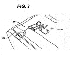
- Each of chambers 12 and 14 has a large door 60 having a floating hinge mechanism 62 and interlocking latch 64.
- the latch 64 is connected to the control system 48 and plasma generator 44 to extinguish the plasma if the door 60 is opened during the cycle when there is plasma present or when the concentration of sterilant is too high.
- a pneumatic piston 65 under control of the control system 48, extends over the latch 64 to prevent opening of the latch during unsafe conditions.
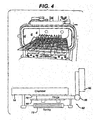
- FIG. 4 shows the hinge mechanism 62 which comprises a hinge 66 attached to the door 60 and slideably attached to the outer wall of the chamber 12 or 14.
- the hinge 66 is trapped between an outer plate 68 and an inner plate 70 while retaining freedom to slide therebetween.
- the plates 68 and 70 are formed out of or coated with a low friction substance such as polytetrafluoroethylene (PTFE).
- PTFE polytetrafluoroethylene
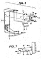
- FIGS. 5 to 7 show an alternative version hinge mechanism 74.
- a hinge mounting bracket 76 affixes to a chamber 78.
- Two mounting plates 80 connect to the bracket 76 via screws 82 passing through elongated slots 84 in the mounting plate 80 so as to provide a limited degree of lateral movement of the plate 80 relative to the bracket 76.
- the screws 82 comprise an unthreaded shoulder 85 between machine threads 86 and a head 88 to allow easy movement of the shoulder 85 within the slots 84.
- A.spring 90 biases the mounting plate 80 away from a door 92.
- TWO hinges 94 attach to the door 92 and have connectors 96 extending therefrom toward the mounting plates 80.
- a clip plate 98 attaches to each mounting plate 80 and has rear notches 100 and front notches 102 into which snap respectively a proximal pin 104 and distal catch 106 on the connectors 96 thus allowing easy attachment and detachment of the door 92.
- a latch 108 is provided on a side of the door 92 opposite the hinges 94.
- a seal 109 about an opening 111 into the chamber 78 and between the door 92 and the chamber 78 helps preserve a vacuum in the chamber 78.
- hinges 94 are shown slidably attached to the chamber 78, one of skill in the art would see that their design could be modified to slidably attach the hinges 94 to the door 92. Further, rather than allow movement at the hinges to normalize forces on the door seal 109, movement could instead be provided at the latch 108 or at both the latch 108 and the hinges 94.
- FIG. 8 shows a rack 110 suitable for holding twenty flat test packs (not shown), each containing a biological indicator, for use within the large test chamber 14.
- FIG. 9 shows a rack 112 suitable for holding four biological indicators within the cylindrical test chamber 16.
- An open circular ring 114 having evenly spaced holder 116 about its circumference fits snugly within the test chamber 16.
- Each holder 116 has a pair of end flanges 118 between which can be placed a biological indicator.
- a typical cycle in the BIER vessel 10 comprises the following.
- OPTIONALLY Heat the vaporizer chamber 12 to 65° C, the large test chamber 14 to 50° C, and the small test chambers or ports 16 to 45° C. The temperature differentials cause small pressure gradients in the gas which can be manipulated to help control gas flow.
- the vacuum and plasma both aid in eliminating any possible residuals, such as water or sterilant from a prior cycle, in the vessel.
- the 0.2 Torr pressure can be maintained with the throttling valves so that opens and closes to raise or lower pressure.
- Vent all chambers 12, 14 and 16 to atmospheric pressure and load samples. Samples are preferably positioned within all portions of the chamber 14 so that when sterilant is introduced into the portions, it exppses all samples equally.
- Plasma may be introduced to condition/heat the samples/load. Stop the plasma at the end of the conditioning time.
- sterilant such as 59% hydrogen peroxide solution
- sterilant monitor 28 therein. If too much is accidentally introduced, a small portion can be evacuated out.
- the addition and removal of sterilant can be manipulated until the desired sterilant concentration and pressure is achieved.
- the sterilant in the vaporizer chamber 12 will cause the pressure to rise higher than the other portions of the vessel that are currently at 0.2 Torr. Once the valves 20 or 22 isolating the other portions of the vessel are opened, the pressure (and temperature) differentials will immediately force the sterilant into the pother portions of the vessel. OPTIONALLY: The valves 22 do not have to be opened or closed simultaneously, allowing for different exposure times for different samples.
- evacuate the vessel portions to 0.2 Torr to remove the remaining sterilant before opening the doors to remote the samples.
- the evacuation time will be less than 30 seconds for the chambers and less than 5 seconds for the Ports.
- plasma may be introduced to enhance the removal of sterilant residual.
Landscapes
- Health & Medical Sciences (AREA)
- Animal Behavior & Ethology (AREA)
- Epidemiology (AREA)
- Life Sciences & Earth Sciences (AREA)
- General Health & Medical Sciences (AREA)
- Public Health (AREA)
- Veterinary Medicine (AREA)
- Plasma & Fusion (AREA)
- Engineering & Computer Science (AREA)
- Physics & Mathematics (AREA)
- Chemical & Material Sciences (AREA)
- Chemical Kinetics & Catalysis (AREA)
- General Chemical & Material Sciences (AREA)
- Apparatus For Disinfection Or Sterilisation (AREA)
Applications Claiming Priority (2)
| Application Number | Priority Date | Filing Date | Title |
|---|---|---|---|
| US10/609,771 US7357896B2 (en) | 2003-06-30 | 2003-06-30 | Resistometer |
| US609771 | 2003-06-30 |
Publications (1)
| Publication Number | Publication Date |
|---|---|
| EP1493449A1 true EP1493449A1 (de) | 2005-01-05 |
Family
ID=33435374
Family Applications (1)
| Application Number | Title | Priority Date | Filing Date |
|---|---|---|---|
| EP04253886A Withdrawn EP1493449A1 (de) | 2003-06-30 | 2004-06-29 | Testvorrichtung für Sterilizationsindikatoren |
Country Status (3)
| Country | Link |
|---|---|
| US (1) | US7357896B2 (de) |
| EP (1) | EP1493449A1 (de) |
| JP (1) | JP2005021686A (de) |
Cited By (4)
| Publication number | Priority date | Publication date | Assignee | Title |
|---|---|---|---|---|
| EP1704873A1 (de) * | 2005-03-24 | 2006-09-27 | Fedegari Autoclavi Spa | Methode und Vorrichtung zur Kennzeichnung von biologischen Indikatoren in Sterilisationsverfahren |
| WO2010144107A1 (en) | 2009-06-11 | 2010-12-16 | Sterilucent, Inc. | Improved apparatus and method for drying and then sterilizing objects in a load using a chemical sterilant |
| CN102160897A (zh) * | 2010-02-20 | 2011-08-24 | 中国石油化工集团公司 | 无菌制造过程中工艺设备及管道系统在线灭菌终点的监测方法 |
| CN103037906A (zh) * | 2011-06-30 | 2013-04-10 | 深圳市仁能达科技有限公司 | 等离子体灭菌设备及其灭菌方法 |
Families Citing this family (8)
| Publication number | Priority date | Publication date | Assignee | Title |
|---|---|---|---|---|
| US7544325B2 (en) * | 2003-11-25 | 2009-06-09 | American Sterilizer Company | BIER vessel high-speed biological indicator shuttling system |
| US20070098591A1 (en) * | 2005-10-31 | 2007-05-03 | Georg Frinke | Method and apparatus for low energy vaporization of liquid oxidizing agents or solutions |
| US10815516B2 (en) * | 2014-12-03 | 2020-10-27 | Tso3 Inc. | Method for establishing resistance characteristics of a biological indicator |
| JP6843761B2 (ja) * | 2015-04-09 | 2021-03-17 | スリーエム イノベイティブ プロパティズ カンパニー | 自動内視鏡洗浄装置用のプロセスチャレンジデバイス |
| US10864291B2 (en) | 2017-12-26 | 2020-12-15 | Asp Global Manufacturing Gmbh | Process and apparatus for cleaning, disinfection, sterilization, or combinations thereof |
| US12076458B2 (en) * | 2020-05-13 | 2024-09-03 | American Sterilizer Company | Disinfection process sampling device |
| CN113124928B (zh) * | 2021-04-08 | 2022-06-24 | 杭州滨昇科技有限公司 | 一种基于充电式的灭菌温湿度记录仪 |
| US20260083871A1 (en) * | 2024-09-24 | 2026-03-26 | Noxilizer, Inc. | Sterilization methods |
Citations (3)
| Publication number | Priority date | Publication date | Assignee | Title |
|---|---|---|---|---|
| US4973449A (en) * | 1986-03-10 | 1990-11-27 | Mdt Corporation | Sterilization method |
| US5482684A (en) * | 1994-05-03 | 1996-01-09 | Abtox, Inc. | Vessel useful for monitoring plasma sterilizing processes |
| US20030086820A1 (en) * | 2001-10-05 | 2003-05-08 | Steris Inc. | Decontamination of surfaces contaminated with prion-infected material with gaseous oxidixing agents |
Family Cites Families (9)
| Publication number | Priority date | Publication date | Assignee | Title |
|---|---|---|---|---|
| US4801421A (en) * | 1985-06-04 | 1989-01-31 | Westinghouse Electric Corp. | On-line monitoring and analysis of reactor vessel integrity |
| US5667753A (en) * | 1994-04-28 | 1997-09-16 | Advanced Sterilization Products | Vapor sterilization using inorganic hydrogen peroxide complexes |
| US5656238A (en) * | 1994-10-11 | 1997-08-12 | Johnson & Johnson Medical, Inc. | Plasma-enhanced vacuum drying |
| US6156267A (en) * | 1996-02-16 | 2000-12-05 | Steris Corporation | Apparatus and method for real-time monitoring and control of anti-microbial processing |
| AU753047B2 (en) * | 1997-11-14 | 2002-10-03 | Ethicon Inc. | Method for measuring the concentration of hydrogen peroxide vapor |
| US6537491B1 (en) * | 1999-07-26 | 2003-03-25 | Abbott Laboratories | Apparatus having sterilant monitoring system |
| US6447719B1 (en) * | 2000-10-02 | 2002-09-10 | Johnson & Johnson | Power system for sterilization systems employing low frequency plasma |
| US6852277B2 (en) * | 2000-10-02 | 2005-02-08 | Ethicon, Inc. | Sterilization system employing a switching module adapted to pulsate the low frequency power applied to a plasma |
| US6936434B2 (en) * | 2001-04-17 | 2005-08-30 | Steris Inc. | Vapor phase decontamination process biological indicator evaluator resistomer (BIER) vessel |
-
2003
- 2003-06-30 US US10/609,771 patent/US7357896B2/en not_active Expired - Lifetime
-
2004
- 2004-06-29 EP EP04253886A patent/EP1493449A1/de not_active Withdrawn
- 2004-06-29 JP JP2004191885A patent/JP2005021686A/ja active Pending
Patent Citations (3)
| Publication number | Priority date | Publication date | Assignee | Title |
|---|---|---|---|---|
| US4973449A (en) * | 1986-03-10 | 1990-11-27 | Mdt Corporation | Sterilization method |
| US5482684A (en) * | 1994-05-03 | 1996-01-09 | Abtox, Inc. | Vessel useful for monitoring plasma sterilizing processes |
| US20030086820A1 (en) * | 2001-10-05 | 2003-05-08 | Steris Inc. | Decontamination of surfaces contaminated with prion-infected material with gaseous oxidixing agents |
Cited By (6)
| Publication number | Priority date | Publication date | Assignee | Title |
|---|---|---|---|---|
| EP1704873A1 (de) * | 2005-03-24 | 2006-09-27 | Fedegari Autoclavi Spa | Methode und Vorrichtung zur Kennzeichnung von biologischen Indikatoren in Sterilisationsverfahren |
| US8163234B2 (en) | 2005-03-24 | 2012-04-24 | Fedegari Autoclavi Spa | Method for characterizing biological indicators in sterilization processes and apparatus for the implementation thereof |
| WO2010144107A1 (en) | 2009-06-11 | 2010-12-16 | Sterilucent, Inc. | Improved apparatus and method for drying and then sterilizing objects in a load using a chemical sterilant |
| EP2440256A4 (de) * | 2009-06-11 | 2015-05-06 | Sterilucent Inc | Verbesserte vorrichtung und verfahren zum trocknen und sterilisation von objekten in einer ladung mittels eines chemischen sterilisationsmittel |
| CN102160897A (zh) * | 2010-02-20 | 2011-08-24 | 中国石油化工集团公司 | 无菌制造过程中工艺设备及管道系统在线灭菌终点的监测方法 |
| CN103037906A (zh) * | 2011-06-30 | 2013-04-10 | 深圳市仁能达科技有限公司 | 等离子体灭菌设备及其灭菌方法 |
Also Published As
| Publication number | Publication date |
|---|---|
| JP2005021686A (ja) | 2005-01-27 |
| US7357896B2 (en) | 2008-04-15 |
| US20040265945A1 (en) | 2004-12-30 |
Similar Documents
| Publication | Publication Date | Title |
|---|---|---|
| EP1110557B1 (de) | Verfahren zum Sterilisieren von Geräten in einem Behälter | |
| US7357896B2 (en) | Resistometer | |
| AU758584B2 (en) | Sterilization process using small amount of sterilant to determime the load | |
| RU2392970C2 (ru) | Система стерилизации | |
| CN107050490B (zh) | 灭菌过程验证装置和方法 | |
| US20020160440A1 (en) | Vapor phase decontamination process biological indicator evaluator resistomer (BIER) vessel | |
| CA2225167C (en) | Two-step sterilization process using liquid sterilant | |
| EP0834324B1 (de) | Verfahren und Vorrichtung zur Detektion von eingeschlossenem Wasser in einer Vakuumkammer | |
| US11273231B2 (en) | Packaging for use in a decontamination system | |
| EP4483908A2 (de) | Vorrichtung und verfahren zur sterilisation eines artikels | |
| KR20170127364A (ko) | 진공 챔버 내의 수분을 검출하는 장치 및 방법 | |
| EP3570898B1 (de) | Verfahren zum nachweis und flüssigkeiten und trocknen | |
| EP1793869B1 (de) | Detektion des taupunkts eines sterilisationsdampfes | |
| EP1493450B1 (de) | Türschliessvorrictung für einen Vakuumsterilisator |
Legal Events
| Date | Code | Title | Description |
|---|---|---|---|
| PUAI | Public reference made under article 153(3) epc to a published international application that has entered the european phase |
Free format text: ORIGINAL CODE: 0009012 |
|
| AK | Designated contracting states |
Kind code of ref document: A1 Designated state(s): AT BE BG CH CY CZ DE DK EE ES FI FR GB GR HU IE IT LI LU MC NL PL PT RO SE SI SK TR |
|
| AX | Request for extension of the european patent |
Extension state: AL HR LT LV MK |
|
| 17P | Request for examination filed |
Effective date: 20050613 |
|
| AKX | Designation fees paid |
Designated state(s): DE ES FR GB IT |
|
| STAA | Information on the status of an ep patent application or granted ep patent |
Free format text: STATUS: THE APPLICATION IS DEEMED TO BE WITHDRAWN |
|
| 18D | Application deemed to be withdrawn |
Effective date: 20100105 |