EP1493485B1 - Mélangeur statique - Google Patents
Mélangeur statique Download PDFInfo
- Publication number
- EP1493485B1 EP1493485B1 EP04405218A EP04405218A EP1493485B1 EP 1493485 B1 EP1493485 B1 EP 1493485B1 EP 04405218 A EP04405218 A EP 04405218A EP 04405218 A EP04405218 A EP 04405218A EP 1493485 B1 EP1493485 B1 EP 1493485B1
- Authority
- EP
- European Patent Office
- Prior art keywords
- flow
- obstacles
- mixing
- static mixer
- accordance
- Prior art date
- Legal status (The legal status is an assumption and is not a legal conclusion. Google has not performed a legal analysis and makes no representation as to the accuracy of the status listed.)
- Expired - Lifetime
Links
Images
Classifications
-
- B—PERFORMING OPERATIONS; TRANSPORTING
- B01—PHYSICAL OR CHEMICAL PROCESSES OR APPARATUS IN GENERAL
- B01F—MIXING, e.g. DISSOLVING, EMULSIFYING OR DISPERSING
- B01F25/00—Flow mixers; Mixers for falling materials, e.g. solid particles
- B01F25/40—Static mixers
- B01F25/42—Static mixers in which the mixing is affected by moving the components jointly in changing directions, e.g. in tubes provided with baffles or obstructions
- B01F25/43—Mixing tubes, e.g. wherein the material is moved in a radial or partly reversed direction
- B01F25/431—Straight mixing tubes with baffles or obstructions that do not cause substantial pressure drop; Baffles therefor
- B01F25/4315—Straight mixing tubes with baffles or obstructions that do not cause substantial pressure drop; Baffles therefor the baffles being deformed flat pieces of material
-
- B—PERFORMING OPERATIONS; TRANSPORTING
- B01—PHYSICAL OR CHEMICAL PROCESSES OR APPARATUS IN GENERAL
- B01F—MIXING, e.g. DISSOLVING, EMULSIFYING OR DISPERSING
- B01F25/00—Flow mixers; Mixers for falling materials, e.g. solid particles
- B01F25/30—Injector mixers
- B01F25/31—Injector mixers in conduits or tubes through which the main component flows
- B01F25/314—Injector mixers in conduits or tubes through which the main component flows wherein additional components are introduced at the circumference of the conduit
- B01F25/3141—Injector mixers in conduits or tubes through which the main component flows wherein additional components are introduced at the circumference of the conduit with additional mixing means other than injector mixers
-
- B—PERFORMING OPERATIONS; TRANSPORTING
- B01—PHYSICAL OR CHEMICAL PROCESSES OR APPARATUS IN GENERAL
- B01F—MIXING, e.g. DISSOLVING, EMULSIFYING OR DISPERSING
- B01F25/00—Flow mixers; Mixers for falling materials, e.g. solid particles
- B01F25/40—Static mixers
- B01F25/42—Static mixers in which the mixing is affected by moving the components jointly in changing directions, e.g. in tubes provided with baffles or obstructions
- B01F25/43—Mixing tubes, e.g. wherein the material is moved in a radial or partly reversed direction
- B01F25/431—Straight mixing tubes with baffles or obstructions that do not cause substantial pressure drop; Baffles therefor
- B01F25/4316—Straight mixing tubes with baffles or obstructions that do not cause substantial pressure drop; Baffles therefor the baffles being flat pieces of material, e.g. intermeshing, fixed to the wall or fixed on a central rod
-
- B—PERFORMING OPERATIONS; TRANSPORTING
- B01—PHYSICAL OR CHEMICAL PROCESSES OR APPARATUS IN GENERAL
- B01F—MIXING, e.g. DISSOLVING, EMULSIFYING OR DISPERSING
- B01F25/00—Flow mixers; Mixers for falling materials, e.g. solid particles
- B01F25/40—Static mixers
- B01F25/42—Static mixers in which the mixing is affected by moving the components jointly in changing directions, e.g. in tubes provided with baffles or obstructions
- B01F25/43—Mixing tubes, e.g. wherein the material is moved in a radial or partly reversed direction
- B01F25/432—Mixing tubes, e.g. wherein the material is moved in a radial or partly reversed direction with means for dividing the material flow into separate sub-flows and for repositioning and recombining these sub-flows; Cross-mixing, e.g. conducting the outer layer of the material nearer to the axis of the tube or vice-versa
- B01F25/4322—Mixing tubes, e.g. wherein the material is moved in a radial or partly reversed direction with means for dividing the material flow into separate sub-flows and for repositioning and recombining these sub-flows; Cross-mixing, e.g. conducting the outer layer of the material nearer to the axis of the tube or vice-versa essentially composed of stacks of sheets, e.g. corrugated sheets
Definitions
- the invention relates to a static mixer for a low-viscosity fluid with mixed internals, which are arranged in a tube or a fluid-conducting container.
- the invention also relates to a method for mixing with the static mixer according to the invention.
- the quality of mixing of a static mixer is understood as a measure of the homogenization which relates to the radial concentration distribution: the smaller the inhomogeneities of this radial distribution, the better the mixing quality.
- the inhomogeneities given by the axial concentration gradients can have the same order of magnitude as the inhomogeneities with respect to the radial concentration distributions. This could be determined by a measurement procedure in which the mixing quality was recorded at a high frequency (20 measurements per second).
- these axial inhomogeneities or temporal variations may be of considerable importance: for example, in a rapid chemical reaction between the components to be mixed, or in a Control of the flow rate of an additive, which is made with respect to concentrations measured in the tube.
- the object of the invention is to provide a static mixer, which does not have the disadvantages in terms of axial inhomogeneities when using a single mixing element or a minimum number of structural elements of the internals and thus - despite low installation costs - ensures a high quality of the mixture.
- This object is achieved by the static mixer defined in claim 1.
- the static mixer for a low-viscosity fluid contains mixed internals, which are arranged in a tube or a fluid-conducting container.
- the geometry of the internals is largely that of a basic structure.
- the internals include structural elements in the form of flat, folded or curved sheet-like flow obstacles and bottlenecks therebetween.
- a flow of the first order can be achieved, which in the downstream mixing areas is a flow which mixes the pipe contents globally.
- the structural elements of the basic structure can be described as segments, webs, plates and / or wings.
- the structural elements - hereinafter referred to as "primary flow obstacles" - are geometrically modified on surfaces and / or on edges.
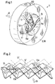
- a mixer 1 according to the invention which has a special configuration, is partially shown in FIG.
- This static mixer 1 with which a low-viscosity fluid 20 can be homogenized, consists of a section of a tube 3 and mixing-effective internals 10, which are arranged in the tube 3. Only one annular part 30 of the tube 3 is shown. This part 30 is mounted on a flange transition of the pipe 3, not shown.
- the mixing-active internals 10 of this embodiment can also be arranged in a tube 3 at a location which is not formed as a flange transition.
- the geometry of the internals 10 is largely that of a basic structure having structural elements 11, 11 'and 12 in the form of segmental or wing-like flow obstructions. Due to bottlenecks between the structural elements flows the fluid 20, whose flow is indicated by arrows 21.
- the structural elements of the basic structure which can be described as segments, webs, plates and / or wings, are hereinafter referred to as "primary flow obstacles”. These primary flow obstacles 11, 11 'and 12 are geometrically modified at the edges, namely by secondary flow obstacles 11a, 11a' and 12a, which are lamellar in the embodiment of FIG.
- the secondary flow obstacles 11 a, 11 a 'and 12 a increase the pressure loss.
- the pressure loss increase is smaller than if instead additional primary flow obstacles corresponding to the obstacles 11, 11 'and 12 - ie additional mixing elements - would be used. Such would be necessary if the secondary flow obstacles 11 a, 11 a 'and 12 a would be omitted.
- the secondary obstacles are too regarding the use of energy.
- the primary flow obstacles 11, 11 ', 12 are so geometrically modified on surfaces and / or edges by the secondary flow obstacles 11 a, 11 a and 12 a that local modifications of second order are inducible by these modifications, the first flow Overlay order and thus improve the quality of mixing.
- the mixing quality is improved by balancing radial and axial inhomogeneities in the fluid better than by the first-order flow, without at the same time increasing the pressure drop by more than about 100%.
- the secondary flow obstacles 11 a, 11 'a and 12 a are arranged on edge portions of the primary flow obstacles 11, 11' and 12. They thus form modifications of the primary flow obstacles 11, 11 'and 12 and locally intensify the turbulence and / or induce backflow of the fluid 20, whereby the mixing is improved.
- the secondary flow obstacles 11 a, 11 'a and 12 a lamellar or rib-shaped and arranged transversely to the local flow direction of the flow of first order on or on the primary flow obstacles.
- a main flow direction is defined perpendicular to the pipe cross-section.
- the tube cross section is largely completely covered by a normal projection of the primary flow obstructions 11, 11 'and 12 in the main flow direction.
- the pipe cross-section is not covered by the normal projections of the individual flow obstacles 11, 11 'and 12 multiple times; or the projection has only marginal overlap zones.
- the tube 3 is cylindrical and the primary flow obstacles 11, 11 'and 12 form a mirror-symmetrical arrangement, with a plane of symmetry in which the tube axis lies.
- the pair 11, 11 'of segmental, largely in one lying common plane structural elements form a bottleneck, within which the wing or web-shaped structural element 12, the plane of the two other structural elements 11, 11 'is arranged crossing.
- the basic structure is a cross-channel structure, in which a plurality of zigzag-folded sheets 13, 14 (and dash-dotted line indicated plates 13 ', 14') form the primary flow obstacles.
- Ribs 13a and / or wire-like elevations 13b are arranged on the sheet metal surfaces of the cross-channel structure.
- the ribs 13a are advantageously sharp-edged and serve as trailing edges on the overflowed folding edges.
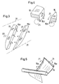
- FIG. 3 shows internals 10 of a mixer 1 according to the invention with two segment-like structural elements 15.
- the secondary flow obstacles 15a of the structural elements 15 are lamellar.
- the inside of the tube 3 is indicated by the dotted lines 31.
- a cross section through the structural elements 15 is shown in FIG. 4.
- the arrows 21 indicate how backflows form behind the structural elements 15.
- Fig. 5 shows a built-in with two vanes 15 as structural elements. In one of the vanes 15 secondary flow obstacles 15a are shown.
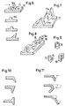
- FIG. 6 shows secondary flow obstacles 16a in four sub-images, in the first as a perspective view and in the other sub-images only as cross-sectional profiles. These obstacles 16 a are rib-shaped and arranged on an overflow surface of a primary flow obstacle 16.
- Figures 7 and 8 show secondary flow obstructions 17a and 18a, respectively, which form linear elements: one with toothed edge and one with separate teeth 19. Examples of further forms of teeth 19 are shown in three partial images of Figure 9.
- the linear element 17a may also have a wavy edge instead of a toothed edge.
- Such geometric modification at the edge of the primary flow obstruction results in an extension of the edge, which advantageously results in an increased formation of turbulence.
- Fig. 10 shows milled secondary flow obstructions (three sub-images) arranged in the form of linear elements on an edge of the primary flow obstruction.
- Fig. 11 shows secondary flow obstructions, each made at the primary flow obstruction by reshaping the rim thereof: slightly bent (first sub-image), heavily bent (second sub-image) and doubly curved (third sub-image) as indicated by arrows, respectively. Similar forms of flow obstructions can also be realized by welding metal strips to the primary flow obstructions.
- the embodiment of FIG. 1 contains a feed point 100 for additives in the pipe section 30.
- the feed point 100 opens with advantage in a zone of the mixing areas, in which the influence of the flow through the geometric modifications is particularly strong. It can also be provided a plurality of feed 100. But more advantageous is a single feed 100, which can be optimally arranged with respect to the fixtures 10. Experience has shown that a plurality of feed points 100 for a single additive are associated with problems that are eliminated at a single feed 100.
- the mixer 1 according to the invention is used to carry out a mixing process in which the fluid 50 to be mixed is transported through the mixer 1 in a preferred direction. With regard to this preferred direction, a better mixing quality than in the opposite direction is achieved.
- the mixing quality improves when the flow on the inlet side is turbulent. It may therefore also be advantageous for the mixing method according to the invention if the fluid 20, before it is passed into the mixing-active internals 10, into a hydrodynamic state in which it has turbulent flow components or increased turbulence.
Landscapes
- Chemical & Material Sciences (AREA)
- Chemical Kinetics & Catalysis (AREA)
- Dispersion Chemistry (AREA)
Claims (9)
- Mélangeur (1) statique pour un fluide (20) à faible viscosité, comprenant des inserts (10) efficaces au niveau du mélange, qui sont disposés dans un tuyau (3) ou un récipient véhiculant le fluide et dont la géométrie est largement celle d'une structure de base, lesquels inserts présentent des éléments de structure (11, 11', 12) sous la forme d'obstacles à l'écoulement de type tôle, plats, pliés ou incurvés et des goulots d'étranglement intercalés, un écoulement de premier ordre pouvant être obtenu par des inserts sous la forme de la structure de base, qui est un écoulement mélangeant globalement le contenu du tuyau dans des zones de mélange situées en aval, et les éléments de structure de la structure de base pouvant être décrits comme des segments, des nervures, des plaques et/ou des ailettes, les éléments de structure - appelés ci-dessous "obstacles à l'écoulement primaires" (11, 11', 12) - étant modifiés au plan géométrique sur des surfaces et/ou sur des bords de telle sorte que ces modifications peuvent induire des écoulements locaux de second ordre qui se superposent à l'écoulement de premier ordre et améliorent ainsi la qualité du mélange, c'est-à-dire de telle sorte que des manques d'homogénéité radiaux et axiaux dans le fluide peuvent être mieux compensés que par l'écoulement de premier ordre, une direction d'écoulement principale perpendiculairement à la section du tuyau étant définie par le tuyau (3), la section de tuyau étant largement complètement (11, 11', 12) recouverte par une projection normale des conditions d'écoulement primaires dans la direction d'écoulement principale et la section de tuyau n'étant pas couverte plusieurs fois par les projections normales des obstacles à l'écoulement individuels ou présentant seulement des zones de chevauchement marginales.
- Mélangeur statique selon la revendication 1, caractérisé en ce que des obstacles à l'écoulement (11a, 11a', 12a) secondaires forment les modifications par lesquelles la turbulence est intensifiée localement et/ou des reflux sont induits, des obstacles secondaires étant disposés avantageusement sur des parties de bordure des obstacles à l'écoulement (11, 11', 12) primaires.
- Mélangeur statique selon la revendication 2, caractérisé en ce que les obstacles à l'écoulement (11a, 11a', 12a) secondaires sont conçus en forme de lamelles et de nervures et sont disposés transversalement à la direction d'écoulement locale de l'écoulement de premier ordre sur les obstacles à l'écoulement (11, 11', 12) primaires.
- Mélangeur statique selon l'une quelconque des revendications 1 à 3, caractérisé en ce que ce qui suit est valable au moins approximativement, en ce que le tuyau (3) est cylindrique et les obstacles à l'écoulement (11, 11', 12) primaires forment un dispositif symétrique, avec un plan de symétrie dans lequel se trouve l'axe du tuyau et en ce qu'une paire d'éléments de structure (11, 11') en forme de segment et située dans un plan, forme un goulot d'étranglement, à l'intérieur duquel est disposé en particulier un élément de structure (12) en forme d'ailette ou de nervure en croisant le plan des deux autres éléments de structure.
- Mélangeur statique selon l'une quelconque des revendications 1 à 4, caractérisé en ce que la structure de base est une structure de canal en croix, sur laquelle une pluralité de tôles (13, 14) pliées en zigzag forment les obstacles à l'écoulement primaires et en ce que des nervures (13a) et/ou des élévations (13b) du type fil sont disposées sur les surfaces de tôle de la structure de canal en croix, les nervures étant réalisées avantageusement avec un bord tranchant et servant d'arêtes de déchirure sur des arêtes de pliage recouvertes.
- Mélangeur statique selon la revendication 1 ou 2, caractérisé en ce que, par les modifications géométriques, on obtient un prolongement des arêtes sur les obstacles à l'écoulement (11, 11', 12) primaires, par exemple par des obstacles à l'écoulement secondaires, qui présentent un bord ondulé ou dentelé, ou en ce que les obstacles à l'écoulement (17a) secondaires présentent un bord à forme ondulée ou denté et sont disposés sur une surface inondée d'un obstacle à l'écoulement (17) primaire.
- Mélangeur statique selon l'une quelconque des revendications 1 à 5, caractérisé en ce que le tuyau contient un point d'injection (100) pour des additifs et en ce que le point d'injection débouche dans une zone des secteurs de mélange dans laquelle l'influence de l'écoulement par les modifications géométriques est réalisée particulièrement fortement.
- Procédé pour le mélange avec un mélangeur (1) statique selon l'une quelconque des revendications 1 à 7, caractérisé en ce que le fluide (20) à mélanger est transporté dans une direction préférentielle par le mélangeur, une qualité de mélange meilleure que dans le sens inverse étant obtenue avec cette direction préférentielle.
- Procédé selon la revendication 8, caractérisé en ce que le fluide (20) est amené, avant qu'il soit guidé dans les inserts (10) efficaces au niveau du mélange, dans un état hydrodynamique dans lequel il présente des composants d'écoulement turbulents ou une turbulence renforcée.
Priority Applications (1)
| Application Number | Priority Date | Filing Date | Title |
|---|---|---|---|
| EP04405218A EP1493485B1 (fr) | 2003-05-08 | 2004-04-08 | Mélangeur statique |
Applications Claiming Priority (3)
| Application Number | Priority Date | Filing Date | Title |
|---|---|---|---|
| EP03405324 | 2003-05-08 | ||
| EP03405324 | 2003-05-08 | ||
| EP04405218A EP1493485B1 (fr) | 2003-05-08 | 2004-04-08 | Mélangeur statique |
Publications (2)
| Publication Number | Publication Date |
|---|---|
| EP1493485A1 EP1493485A1 (fr) | 2005-01-05 |
| EP1493485B1 true EP1493485B1 (fr) | 2006-05-31 |
Family
ID=33436137
Family Applications (1)
| Application Number | Title | Priority Date | Filing Date |
|---|---|---|---|
| EP04405218A Expired - Lifetime EP1493485B1 (fr) | 2003-05-08 | 2004-04-08 | Mélangeur statique |
Country Status (1)
| Country | Link |
|---|---|
| EP (1) | EP1493485B1 (fr) |
Families Citing this family (4)
| Publication number | Priority date | Publication date | Assignee | Title |
|---|---|---|---|---|
| DE102006011890A1 (de) * | 2006-03-15 | 2007-09-20 | Robert Bosch Gmbh | Verfahren zur Herstellung einer Mischvorrichtung für eine Abgasnachbehandlungsvorrichtung, Mischvorrichtung für eine Abgasnachbehandlungsvorrichtung sowie Anordnung mit einer solchen Mischvorrichtung |
| GB201100673D0 (en) | 2011-01-15 | 2011-03-02 | Statiflo Internat Ltd | Static mixer assembly |
| CN109701410B (zh) * | 2019-02-21 | 2024-03-29 | 中南大学 | 一种管道静态混合矿化装置 |
| CN113083056B (zh) * | 2021-05-13 | 2025-05-13 | 洛阳德明石化设备有限公司 | 一种蝶式静态混合器 |
Family Cites Families (4)
| Publication number | Priority date | Publication date | Assignee | Title |
|---|---|---|---|---|
| US4123178A (en) * | 1977-03-21 | 1978-10-31 | General Signal Corporation | In-line blender |
| FR2438498A1 (fr) * | 1978-10-13 | 1980-05-09 | Degremont | Appareil pour le melange de fluides sous faible gradient de vitesse |
| US4710326A (en) * | 1986-08-29 | 1987-12-01 | Seah Alexander M | Corrugated packing and methods of use |
| US4899812A (en) * | 1988-09-06 | 1990-02-13 | Westinghouse Electric Corp. | Self-securing turbulence promoter to enhance heat transfer |
-
2004
- 2004-04-08 EP EP04405218A patent/EP1493485B1/fr not_active Expired - Lifetime
Also Published As
| Publication number | Publication date |
|---|---|
| EP1493485A1 (fr) | 2005-01-05 |
Similar Documents
| Publication | Publication Date | Title |
|---|---|---|
| EP2277620B1 (fr) | Elément de mélange statique | |
| EP1967806B1 (fr) | Dispositif destiné au traitement par échange thermique et mélange de fluides | |
| EP2851118B1 (fr) | Dispositif de mélange et d'échange thermique et procédé pour sa fabrication | |
| DE102005037026B4 (de) | Kavitationsmischer | |
| EP0526393B1 (fr) | dispositif d'immixtion | |
| EP2286904B1 (fr) | Dispositif de mélange statique pour matières pouvant s'écouler | |
| EP2625144B1 (fr) | Redresseur d'écoulement pour canalisations fermées | |
| DE3043239A1 (de) | Verfahren und vorrichtung zum mischen mindestens zweier teilstraeme mit unterschiedlichen zustandsgroessen | |
| EP1681090A1 (fr) | Dispositif et procédé de mélange d'un courant de fluide dans un conduit | |
| DE2205371A1 (de) | Mischeinrichtung | |
| DE60110602T2 (de) | Statisches mischelement und verfahren zum mischen zweier fluide | |
| WO2008141472A1 (fr) | Canal d'écoulement pour un échangeur de chaleur mélangeur | |
| EP3408013A1 (fr) | Mélangeur-échangeur de chaleur en feuille de trèfle | |
| DE4016673C2 (fr) | ||
| AT502016B1 (de) | Wirbelkammer | |
| DE1675501A1 (de) | Einrichtung zum Verteilen von Stroemungsmedien auf mehrere Durchtrittsoeffnungen | |
| EP2185884B1 (fr) | Ailette pour un échangeur de chaleur | |
| EP1493485A1 (fr) | Mélangeur statique | |
| WO2014127964A1 (fr) | Élément de transfert thermique | |
| DE3214143C2 (fr) | ||
| EP3625511A1 (fr) | Dispositif de refroidissement, chauffage ou transfert thermique | |
| DE102006047526A1 (de) | Strömungsgleichrichter | |
| CH693560A5 (de) | Statische Mischvorrichtung für fliessfähige Stoffe. | |
| EP3081285B1 (fr) | Dispositif de mélange statique pour des matières pouvant s'écouler | |
| DE19539923C1 (de) | Vorrichtung in einem ein Primärfluid führenden Kanal |
Legal Events
| Date | Code | Title | Description |
|---|---|---|---|
| PUAI | Public reference made under article 153(3) epc to a published international application that has entered the european phase |
Free format text: ORIGINAL CODE: 0009012 |
|
| AK | Designated contracting states |
Kind code of ref document: A1 Designated state(s): AT BE BG CH CY CZ DE DK EE ES FI FR GB GR HU IE IT LI LU MC NL PL PT RO SE SI SK TR |
|
| AX | Request for extension of the european patent |
Extension state: AL HR LT LV MK |
|
| 17P | Request for examination filed |
Effective date: 20050608 |
|
| AKX | Designation fees paid |
Designated state(s): AT BE BG CH CY CZ DE DK EE ES FI FR GB GR HU IE IT LI LU MC NL PL PT RO SE SI SK TR |
|
| GRAP | Despatch of communication of intention to grant a patent |
Free format text: ORIGINAL CODE: EPIDOSNIGR1 |
|
| GRAS | Grant fee paid |
Free format text: ORIGINAL CODE: EPIDOSNIGR3 |
|
| GRAA | (expected) grant |
Free format text: ORIGINAL CODE: 0009210 |
|
| AK | Designated contracting states |
Kind code of ref document: B1 Designated state(s): AT BE BG CH CY CZ DE DK EE ES FI FR GB GR HU IE IT LI LU MC NL PL PT RO SE SI SK TR |
|
| PG25 | Lapsed in a contracting state [announced via postgrant information from national office to epo] |
Ref country code: RO Free format text: LAPSE BECAUSE OF FAILURE TO SUBMIT A TRANSLATION OF THE DESCRIPTION OR TO PAY THE FEE WITHIN THE PRESCRIBED TIME-LIMIT Effective date: 20060531 Ref country code: IT Free format text: LAPSE BECAUSE OF FAILURE TO SUBMIT A TRANSLATION OF THE DESCRIPTION OR TO PAY THE FEE WITHIN THE PRESCRIBED TIME-LIMIT;WARNING: LAPSES OF ITALIAN PATENTS WITH EFFECTIVE DATE BEFORE 2007 MAY HAVE OCCURRED AT ANY TIME BEFORE 2007. THE CORRECT EFFECTIVE DATE MAY BE DIFFERENT FROM THE ONE RECORDED. Effective date: 20060531 Ref country code: SI Free format text: LAPSE BECAUSE OF FAILURE TO SUBMIT A TRANSLATION OF THE DESCRIPTION OR TO PAY THE FEE WITHIN THE PRESCRIBED TIME-LIMIT Effective date: 20060531 Ref country code: FI Free format text: LAPSE BECAUSE OF FAILURE TO SUBMIT A TRANSLATION OF THE DESCRIPTION OR TO PAY THE FEE WITHIN THE PRESCRIBED TIME-LIMIT Effective date: 20060531 Ref country code: PL Free format text: LAPSE BECAUSE OF FAILURE TO SUBMIT A TRANSLATION OF THE DESCRIPTION OR TO PAY THE FEE WITHIN THE PRESCRIBED TIME-LIMIT Effective date: 20060531 Ref country code: SK Free format text: LAPSE BECAUSE OF FAILURE TO SUBMIT A TRANSLATION OF THE DESCRIPTION OR TO PAY THE FEE WITHIN THE PRESCRIBED TIME-LIMIT Effective date: 20060531 Ref country code: IE Free format text: LAPSE BECAUSE OF FAILURE TO SUBMIT A TRANSLATION OF THE DESCRIPTION OR TO PAY THE FEE WITHIN THE PRESCRIBED TIME-LIMIT Effective date: 20060531 Ref country code: CZ Free format text: LAPSE BECAUSE OF FAILURE TO SUBMIT A TRANSLATION OF THE DESCRIPTION OR TO PAY THE FEE WITHIN THE PRESCRIBED TIME-LIMIT Effective date: 20060531 |
|
| REG | Reference to a national code |
Ref country code: GB Ref legal event code: FG4D Free format text: NOT ENGLISH Ref country code: CH Ref legal event code: EP |
|
| GBT | Gb: translation of ep patent filed (gb section 77(6)(a)/1977) |
Effective date: 20060531 |
|
| REG | Reference to a national code |
Ref country code: IE Ref legal event code: FG4D Free format text: LANGUAGE OF EP DOCUMENT: GERMAN |
|
| REG | Reference to a national code |
Ref country code: CH Ref legal event code: NV Representative=s name: SULZER MANAGEMENT AG PATENTABTEILUNG/0067 |
|
| REF | Corresponds to: |
Ref document number: 502004000650 Country of ref document: DE Date of ref document: 20060706 Kind code of ref document: P |
|
| PG25 | Lapsed in a contracting state [announced via postgrant information from national office to epo] |
Ref country code: DK Free format text: LAPSE BECAUSE OF FAILURE TO SUBMIT A TRANSLATION OF THE DESCRIPTION OR TO PAY THE FEE WITHIN THE PRESCRIBED TIME-LIMIT Effective date: 20060831 Ref country code: SE Free format text: LAPSE BECAUSE OF FAILURE TO SUBMIT A TRANSLATION OF THE DESCRIPTION OR TO PAY THE FEE WITHIN THE PRESCRIBED TIME-LIMIT Effective date: 20060831 |
|
| PG25 | Lapsed in a contracting state [announced via postgrant information from national office to epo] |
Ref country code: ES Free format text: LAPSE BECAUSE OF FAILURE TO SUBMIT A TRANSLATION OF THE DESCRIPTION OR TO PAY THE FEE WITHIN THE PRESCRIBED TIME-LIMIT Effective date: 20060911 |
|
| PG25 | Lapsed in a contracting state [announced via postgrant information from national office to epo] |
Ref country code: PT Free format text: LAPSE BECAUSE OF FAILURE TO SUBMIT A TRANSLATION OF THE DESCRIPTION OR TO PAY THE FEE WITHIN THE PRESCRIBED TIME-LIMIT Effective date: 20061031 |
|
| ET | Fr: translation filed | ||
| REG | Reference to a national code |
Ref country code: IE Ref legal event code: FD4D |
|
| PLBE | No opposition filed within time limit |
Free format text: ORIGINAL CODE: 0009261 |
|
| STAA | Information on the status of an ep patent application or granted ep patent |
Free format text: STATUS: NO OPPOSITION FILED WITHIN TIME LIMIT |
|
| 26N | No opposition filed |
Effective date: 20070301 |
|
| BERE | Be: lapsed |
Owner name: SULZER CHEMTECH A.G. Effective date: 20070430 |
|
| PG25 | Lapsed in a contracting state [announced via postgrant information from national office to epo] |
Ref country code: BE Free format text: LAPSE BECAUSE OF NON-PAYMENT OF DUE FEES Effective date: 20070430 |
|
| PG25 | Lapsed in a contracting state [announced via postgrant information from national office to epo] |
Ref country code: GR Free format text: LAPSE BECAUSE OF FAILURE TO SUBMIT A TRANSLATION OF THE DESCRIPTION OR TO PAY THE FEE WITHIN THE PRESCRIBED TIME-LIMIT Effective date: 20060901 |
|
| PG25 | Lapsed in a contracting state [announced via postgrant information from national office to epo] |
Ref country code: BG Free format text: LAPSE BECAUSE OF FAILURE TO SUBMIT A TRANSLATION OF THE DESCRIPTION OR TO PAY THE FEE WITHIN THE PRESCRIBED TIME-LIMIT Effective date: 20060831 |
|
| PG25 | Lapsed in a contracting state [announced via postgrant information from national office to epo] |
Ref country code: EE Free format text: LAPSE BECAUSE OF FAILURE TO SUBMIT A TRANSLATION OF THE DESCRIPTION OR TO PAY THE FEE WITHIN THE PRESCRIBED TIME-LIMIT Effective date: 20060531 |
|
| PG25 | Lapsed in a contracting state [announced via postgrant information from national office to epo] |
Ref country code: AT Free format text: LAPSE BECAUSE OF NON-PAYMENT OF DUE FEES Effective date: 20070408 |
|
| PGRI | Patent reinstated in contracting state [announced from national office to epo] |
Ref country code: IT Effective date: 20080601 |
|
| PG25 | Lapsed in a contracting state [announced via postgrant information from national office to epo] |
Ref country code: MC Free format text: LAPSE BECAUSE OF NON-PAYMENT OF DUE FEES Effective date: 20070430 |
|
| PG25 | Lapsed in a contracting state [announced via postgrant information from national office to epo] |
Ref country code: CY Free format text: LAPSE BECAUSE OF FAILURE TO SUBMIT A TRANSLATION OF THE DESCRIPTION OR TO PAY THE FEE WITHIN THE PRESCRIBED TIME-LIMIT Effective date: 20060531 Ref country code: LU Free format text: LAPSE BECAUSE OF NON-PAYMENT OF DUE FEES Effective date: 20070408 |
|
| PG25 | Lapsed in a contracting state [announced via postgrant information from national office to epo] |
Ref country code: TR Free format text: LAPSE BECAUSE OF FAILURE TO SUBMIT A TRANSLATION OF THE DESCRIPTION OR TO PAY THE FEE WITHIN THE PRESCRIBED TIME-LIMIT Effective date: 20060531 Ref country code: HU Free format text: LAPSE BECAUSE OF FAILURE TO SUBMIT A TRANSLATION OF THE DESCRIPTION OR TO PAY THE FEE WITHIN THE PRESCRIBED TIME-LIMIT Effective date: 20061201 |
|
| REG | Reference to a national code |
Ref country code: CH Ref legal event code: PCOW Free format text: NEW ADDRESS: SULZERALLEE 48, 8404 WINTERTHUR (CH) Ref country code: CH Ref legal event code: NV Representative=s name: DR. GRAF AND PARTNER AG INTELLECTUAL PROPERTY, CH |
|
| REG | Reference to a national code |
Ref country code: FR Ref legal event code: PLFP Year of fee payment: 13 |
|
| REG | Reference to a national code |
Ref country code: FR Ref legal event code: PLFP Year of fee payment: 14 |
|
| REG | Reference to a national code |
Ref country code: DE Ref legal event code: R082 Ref document number: 502004000650 Country of ref document: DE Representative=s name: PATENTANWAELTE HENKEL, BREUER & PARTNER MBB, DE Ref country code: DE Ref legal event code: R082 Ref document number: 502004000650 Country of ref document: DE Representative=s name: HENKEL & PARTNER MBB PATENTANWALTSKANZLEI, REC, DE Ref country code: DE Ref legal event code: R082 Ref document number: 502004000650 Country of ref document: DE Representative=s name: PATENTANWAELTE HENKEL, BREUER & PARTNER, DE Ref country code: DE Ref legal event code: R082 Ref document number: 502004000650 Country of ref document: DE Representative=s name: HENKEL, BREUER & PARTNER, DE |
|
| REG | Reference to a national code |
Ref country code: DE Ref legal event code: R082 Ref document number: 502004000650 Country of ref document: DE Representative=s name: PATENTANWAELTE HENKEL, BREUER & PARTNER MBB, DE Ref country code: DE Ref legal event code: R082 Ref document number: 502004000650 Country of ref document: DE Representative=s name: HENKEL & PARTNER MBB PATENTANWALTSKANZLEI, REC, DE Ref country code: DE Ref legal event code: R082 Ref document number: 502004000650 Country of ref document: DE Representative=s name: HENKEL, BREUER & PARTNER, DE |
|
| REG | Reference to a national code |
Ref country code: FR Ref legal event code: PLFP Year of fee payment: 15 |
|
| REG | Reference to a national code |
Ref country code: DE Ref legal event code: R082 Ref document number: 502004000650 Country of ref document: DE Representative=s name: PATENTANWAELTE HENKEL, BREUER & PARTNER MBB, DE Ref country code: DE Ref legal event code: R082 Ref document number: 502004000650 Country of ref document: DE Representative=s name: HENKEL & PARTNER MBB PATENTANWALTSKANZLEI, REC, DE |
|
| REG | Reference to a national code |
Ref country code: DE Ref legal event code: R082 Ref document number: 502004000650 Country of ref document: DE Representative=s name: HENKEL & PARTNER MBB PATENTANWALTSKANZLEI, REC, DE Ref country code: DE Ref legal event code: R081 Ref document number: 502004000650 Country of ref document: DE Owner name: SULZER MANAGEMENT AG, CH Free format text: FORMER OWNER: SULZER CHEMTECH AG, WINTERTHUR, CH |
|
| REG | Reference to a national code |
Ref country code: CH Ref legal event code: PUE Owner name: SULZER MANAGEMENT AG, CH Free format text: FORMER OWNER: SULZER CHEMTECH AG, CH |
|
| REG | Reference to a national code |
Ref country code: GB Ref legal event code: 732E Free format text: REGISTERED BETWEEN 20200723 AND 20200729 |
|
| REG | Reference to a national code |
Ref country code: CH Ref legal event code: NV Representative=s name: DR. GRAF AND PARTNER AG INTELLECTUAL PROPERTY, CH |
|
| REG | Reference to a national code |
Ref country code: NL Ref legal event code: PD Owner name: SULZER MANAGEMENT AG; CH Free format text: DETAILS ASSIGNMENT: CHANGE OF OWNER(S), ASSIGNMENT; FORMER OWNER NAME: SULZER CHEMTECH AG Effective date: 20210805 |
|
| REG | Reference to a national code |
Ref country code: DE Ref legal event code: R079 Ref document number: 502004000650 Country of ref document: DE Free format text: PREVIOUS MAIN CLASS: B01F0005060000 Ipc: B01F0025400000 |
|
| PGFP | Annual fee paid to national office [announced via postgrant information from national office to epo] |
Ref country code: NL Payment date: 20220420 Year of fee payment: 19 |
|
| PGFP | Annual fee paid to national office [announced via postgrant information from national office to epo] |
Ref country code: IT Payment date: 20220420 Year of fee payment: 19 Ref country code: GB Payment date: 20220420 Year of fee payment: 19 Ref country code: FR Payment date: 20220420 Year of fee payment: 19 Ref country code: DE Payment date: 20220420 Year of fee payment: 19 |
|
| PGFP | Annual fee paid to national office [announced via postgrant information from national office to epo] |
Ref country code: CH Payment date: 20220421 Year of fee payment: 19 |
|
| REG | Reference to a national code |
Ref country code: DE Ref legal event code: R119 Ref document number: 502004000650 Country of ref document: DE |
|
| REG | Reference to a national code |
Ref country code: CH Ref legal event code: PL |
|
| REG | Reference to a national code |
Ref country code: NL Ref legal event code: MM Effective date: 20230501 |
|
| GBPC | Gb: european patent ceased through non-payment of renewal fee |
Effective date: 20230408 |
|
| PG25 | Lapsed in a contracting state [announced via postgrant information from national office to epo] |
Ref country code: GB Free format text: LAPSE BECAUSE OF NON-PAYMENT OF DUE FEES Effective date: 20230408 |
|
| PG25 | Lapsed in a contracting state [announced via postgrant information from national office to epo] |
Ref country code: NL Free format text: LAPSE BECAUSE OF NON-PAYMENT OF DUE FEES Effective date: 20230501 Ref country code: LI Free format text: LAPSE BECAUSE OF NON-PAYMENT OF DUE FEES Effective date: 20230430 Ref country code: GB Free format text: LAPSE BECAUSE OF NON-PAYMENT OF DUE FEES Effective date: 20230408 Ref country code: FR Free format text: LAPSE BECAUSE OF NON-PAYMENT OF DUE FEES Effective date: 20230430 Ref country code: DE Free format text: LAPSE BECAUSE OF NON-PAYMENT OF DUE FEES Effective date: 20231103 Ref country code: CH Free format text: LAPSE BECAUSE OF NON-PAYMENT OF DUE FEES Effective date: 20230430 |
|
| PG25 | Lapsed in a contracting state [announced via postgrant information from national office to epo] |
Ref country code: IT Free format text: LAPSE BECAUSE OF FAILURE TO SUBMIT A TRANSLATION OF THE DESCRIPTION OR TO PAY THE FEE WITHIN THE PRESCRIBED TIME-LIMIT Effective date: 20230408 |