EP1493507B1 - Vorrichtung zur Herstellung eines endlosen Metallriemens - Google Patents
Vorrichtung zur Herstellung eines endlosen Metallriemens Download PDFInfo
- Publication number
- EP1493507B1 EP1493507B1 EP04014542A EP04014542A EP1493507B1 EP 1493507 B1 EP1493507 B1 EP 1493507B1 EP 04014542 A EP04014542 A EP 04014542A EP 04014542 A EP04014542 A EP 04014542A EP 1493507 B1 EP1493507 B1 EP 1493507B1
- Authority
- EP
- European Patent Office
- Prior art keywords
- belt
- rolls
- shaping
- pair
- rolling
- Prior art date
- Legal status (The legal status is an assumption and is not a legal conclusion. Google has not performed a legal analysis and makes no representation as to the accuracy of the status listed.)
- Expired - Lifetime
Links
- 238000007493 shaping process Methods 0.000 title claims abstract description 46
- 239000002184 metal Substances 0.000 title claims abstract description 12
- 238000005096 rolling process Methods 0.000 claims abstract description 41
- 230000007704 transition Effects 0.000 claims abstract description 9
- 230000004913 activation Effects 0.000 claims description 6
- 230000001154 acute effect Effects 0.000 claims description 3
- 238000000034 method Methods 0.000 abstract description 9
- 230000008569 process Effects 0.000 description 6
- 239000000463 material Substances 0.000 description 3
- 238000010276 construction Methods 0.000 description 2
- 230000000694 effects Effects 0.000 description 2
- 230000009471 action Effects 0.000 description 1
- 239000008186 active pharmaceutical agent Substances 0.000 description 1
- 230000002411 adverse Effects 0.000 description 1
- 230000008901 benefit Effects 0.000 description 1
- 239000002826 coolant Substances 0.000 description 1
- 238000010438 heat treatment Methods 0.000 description 1
- 238000005259 measurement Methods 0.000 description 1
- 230000003287 optical effect Effects 0.000 description 1
- 230000009467 reduction Effects 0.000 description 1
Images

Classifications
-
- B—PERFORMING OPERATIONS; TRANSPORTING
- B21—MECHANICAL METAL-WORKING WITHOUT ESSENTIALLY REMOVING MATERIAL; PUNCHING METAL
- B21D—WORKING OR PROCESSING OF SHEET METAL OR METAL TUBES, RODS OR PROFILES WITHOUT ESSENTIALLY REMOVING MATERIAL; PUNCHING METAL
- B21D53/00—Making other particular articles
- B21D53/14—Making other particular articles belts, e.g. machine-gun belts
-
- B—PERFORMING OPERATIONS; TRANSPORTING
- B21—MECHANICAL METAL-WORKING WITHOUT ESSENTIALLY REMOVING MATERIAL; PUNCHING METAL
- B21D—WORKING OR PROCESSING OF SHEET METAL OR METAL TUBES, RODS OR PROFILES WITHOUT ESSENTIALLY REMOVING MATERIAL; PUNCHING METAL
- B21D19/00—Flanging or other edge treatment, e.g. of tubes
- B21D19/005—Edge deburring or smoothing
Definitions
- the present invention relates to a device for shaping a continuous metal belt and also to a push belt in which the metal belt is used, as described, inter alia, in the preamble of Claim 1.
- a device for shaping a continuous metal belt and also to a push belt in which the metal belt is used, as described, inter alia, in the preamble of Claim 1.
- Such a device is known from JP-A-2002 248522 .
- a push belt and also the continuous metal belt used therein is generally known, for example from European Patent Publication EP-A 0 181 670 and from Dutch Patent Application No. 1022043 , which was not published before the priority date of the present application, both in the name of the present applicant.
- the latter document also describes a rolling process and device for shaping a belt of this type.
- the metal belt is generally incorporated in the push belt in the form of one or two sets comprising a number of nested metal belts.
- a metal belt of this type is formed by cutting off a ring from a metal tube formed from a material in sheet form and then deforming this ring to produce a desired radial thickness and tangential or circumferential length with the aid of a rolling process, optionally preceded and/or followed by a heat treatment of the belt. Up until the belt undergoes the rolling treatment, it is also referred to as the ring.
- the ring Before the ring is rolled, it is subjected to a tumbling process which is known per se and in which the ring is held for a certain time in a receptacle containing suitable moving tumbling blocks. This serves to remove burrs formed when the ring was being cut from the tube from the axially oriented side faces of the ring. In the process, at least the edges between the said side faces and radially oriented main surfaces of the ring are also rounded slightly.
- the object of the present invention is to improve the quality or at least the appearance of the axially oriented side faces of the belt considerably and to provide a further development of the known shaping process. According to the invention, this object is achieved by a device comprising at least the features of Claim 1. Claims 2-4 describe preferred embodiments of the device.
- the device according to the invention comprises two pairs of shaping rolls of this type positioned opposite one another, with the substantially V-shaped groove of a first pair being provided with a more acute vertex angle than that of the second pair.
- at least a centre part of the V-shaped groove of the second pair is rounded in shape, with the abovementioned vertex angle being defined by an imaginary lengthening of the sides of the contour of the V-shaped groove, at least as seen in the said tangential direction.
- Figure 1 diagrammatically depicts an existing rolling device for rolling metal rings to form belts, which device is illustrated in such a manner that it also provides an insight into the shaping method and shaping device 25 according to the invention.
- the rolling device is described in Dutch Patent Application No. 1022043 , which was not published before the priority date of the present application, and comprises three modules. In this respect, the figure shows, from the right to the left, a first measuring module 1, a rolling module 2 and a second measuring module 3.
- the rolling device is controlled by an electronic control unit, which is not shown in more detail in the figure.
- the measuring modules 1 and 3 comprise measuring rolls 4, 5 around which the belt 10 can be arranged, in such a manner that the thickness of the belt 10 can be measured both before and after the rolling process has been carried out, with the aid of the proximity sensors DS. It is preferable for the said measuring rolls 4, 5 to be moved away from one another, with the belt 10 being subjected to a tensile stress, and for the measurement to be carried out at a number of positions over the circumference of the belt 10, which is of benefit to the accuracy.
- the rolling module 2 comprises two rotatable guide rolls 6, 7, of which a first roll 7 is positioned centrally in the rolling module 2 and around which the belt 10 to be rolled can be arranged.
- a second roll 6 of the guide rolls 6, 7 is held within the rolling module 2 in such a manner that it can be displaced so as to apply a tensile force, for example under the control of first activation means 21.
- the rolling module 2 furthermore comprises a pair of support rolls 12 which act on the first guide roll 7, a rolling roll 11, and a pressure roll 13 acting on the support rolls 12.
- the support rolls 12 are each provided over their circumference with a recess, by means of which they each act on the first guide roll 7 on either side adjacent to the belt 10.
- the pressure roll 13 is accommodated in such a manner that it can be displaced, under the influence of second activation means 22, in the rolling module 2, in such a manner that a pushing force or rolling force can be exerted on the support rolls 12.
- the support rolls 12 transmit the rolling force to the first guide roll 7, which is then supported on the rolling roll 11 via part of the belt 10.
- the belt 10 is held rotating between the first guide roll 7 and the rolling roll 11.
- the rotating movement of the belt 10, the direction of rotation of which is indicated by arrows D, is in this case achieved by driving at least one of the said rolls 6, 7, 11, 12 and 13, with the direction of rotation of the rolls 6, 7, 11, 12 and 13 being indicated by the arrows illustrated therein.
- a tensile force is applied to the belt 10 between the guide rolls 6, 7, and a pushing force is applied to the belt 10 between the rolling roll 11 and the first guide roll 7.
- Figure 1 also diagrammatically depicts the shaping device 25 according to the present invention and the way in which it can be held in the known rolling module 2 in order to process side faces 15 of the belt which are oriented in the width direction, i.e. axially oriented, at the same time as the belt 10 is being rolled.
- the shaping device 25 is preferably coupled to a frame to which one of the rolling rolls is secured, in this case the bearing frame for the pressure roll 13, in such a manner that a correct orientation of the latter with respect to the belt 10 is obtained automatically.
- a bearing arm 31 is provided for this purpose in Figure 1 .
- the shaping device 25 is provided with two pairs of shaping rolls 26, 27, the respective rolls 26, 27 of which are moved towards one another, or at least a pushing force is exerted between them, so that they act on the side faces 15 on either side of the belt 10.
- the shaping rolls 26, 27 are provided over their outer circumference with a concave profile, i.e. a groove, in which the belt 10 is partially accommodated.
- the shaping rolls 26, 27 simultaneously act on the belt 10 in the axial direction, with the side faces 15, and in particular the transition edges 16 (cf. Figures 5 and 6 ) between these side faces and the radially oriented main surfaces 14 of the belt 10 being provided with a desired shape.
- the shaping device 25 should furthermore be provided with means which enable it to be opened and closed, i.e. with means which are responsible for moving the rolls 26, 27 away from one another with a movement component in the axial direction and then bringing them into contact with the belt 10, which can advantageously be achieved in the construction shown by the said means being mechanically coupled to the rolling module 2, it being possible for the latter to follow an opening and closing movement thereof for the purpose of applying and removing the belt 10 to and from the guide rolls 6, 7.
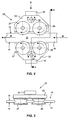
- Figures 2, 3 and 4 diagrammatically depict the arrangement of an embodiment of the shaping device 25 for processing, i.e. shaping, the side faces 15 of the belt 10.
- Figure 2 shows a view transversely onto the circumferential direction of the belt 10, as seen in a direction perpendicular to the main surface 14 thereof
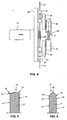
- Figures 3 and 4 each show a view of the shaping device 25, respectively as indicated by arrows A and arrow B in Figure 2 .
- a carrier 30 which is coupled to the bearing arm 31 is provided, in accordance with a preferred embodiment, with two subframes 33 which are each held moveably, i.e. linearly displaceably, with respect to the carrier 30 and with respect to one another.
- the subframes 33 are provided with two processing rolls 26 and 27, which are arranged rotatably thereon.
- an intermediate frame 32 is also provided between the subframes 33 and the carrier 30.
- the intermediate frames 32 are arranged on the carrier 30 in such a manner that they can be displaced linearly with respect to the latter, for example with the aid of a rectilinear guide which is oriented transversely with respect to the said direction of rotation D, and the subframes 33 are arranged on the respective intermediate frame 32 with the aid of an axle 34, so that they can execute an oscillating or rotary motion with respect to the intermediate frame 32 and therefore also with respect to the belt 10 which is to be shaped.
- each of the subframes 33 directly with one processing roll 26, 27 and not using the said intermediate frame 32, or by the two rolls 26, 27 each being separately secured to the carrier 30 in a linearly displaceable manner.
- two activation elements 36 are required in order to move the two pairs of shaping rolls 26 and 27 towards one another, at least in order to exert a pushing force F on the side faces 15 of the belt 10 on either side thereof.
- only one activation element 36 is required (cf. also Figure 4 ).
- the activation element 36 may, for example, realize a controlled force F, but according to the invention may also be realized, in a surprisingly simple way, as a more or less constant spring force F produced by a tension spring 36 arranged between the subframes 33.
- FIGS 2-4 illustrate the processing a side face 15 using two pairs of shaping rolls 26 and 27.
- the shaping rolls 26, 27 are provided over their outer circumference with a concave profile, i.e. a groove, in which the belt 10 is partially accommodated and via which groove the shaping rolls 26, 27 each act on the side faces 15 of the belt from the axial sides thereof, and in particular act on the transition edges 16 between the side faces 15 and the radially oriented main surfaces 14, shaping them during the known rolling process.
- the grooves in the two pairs of shaping rolls 26, 27 are of different shapes, at least as seen in the tangential direction in a cross section thereof.
- the two groove shapes are in this case substantially V-shaped, but in a first pair of shaping rolls 26 the V-shaped groove ends in a discrete, acute vertex angle, while in the other, or second, pair of shaping rolls 26 it ends in an evenly rounded transition, at least at the location of a centre part of the groove, which therefore forms a rounded transition between the side faces of the groove on either side of the centre part.
- This centre part is preferably substantially parabolic in shape.
- the V-shaped groove of the first pair of shaping rolls 26 is preferably narrower than that of the second pair of shaping rolls 27.
- a configuration and shaping of the device 25 of this type also ensures that the first pair of rolls 26 is at least substantially aimed at processing and shaping the said transition edges 16, and that the second pair of rolls 27 is at least substantially aimed at processing and shaping the side face 15 itself (cf. also Figures 5 and 6 ).
- the second pair of shaping rolls 27 it is preferable for the second pair of shaping rolls 27 to be positioned behind the first pair of shaping rolls 26, at least as seen in the direction of rotation D of the belt 10.
- Figures 5 and 6 illustrate the effect of a processing operation in accordance with a more detailed refinement of the present invention of this nature.
- Figure 5 shows a cross section through a part 17 of a belt 10 which is yet to be rolled, i.e. a ring, as is typically obtained after the belt 10 has been cut off a tube, i.e. including a burr 18 which is generally present at the location of a transition edge 16.
- Figure 6 shows the same cross section 17 through the belt 10, but after it has been rolled and, at the same time, processed or shaped in accordance with the invention. It can be seen that the thickness of the belt 10 - i.e.
- the centre part 20 of the side face 15 has clearly been shaped in particular by the second pair of rolls 27 and therefore has a convex profile, at least as seen in cross section 17.
- the side parts 19 of the side face 15 located on either side of the said centre part 20 have clearly been shaped in particular by the first pair of rolls 26 and consequently have a flat profile, at least as seen in cross section 17.
Landscapes
- Engineering & Computer Science (AREA)
- Mechanical Engineering (AREA)
- Press Drives And Press Lines (AREA)
- Casting Or Compression Moulding Of Plastics Or The Like (AREA)
- Laminated Bodies (AREA)
- Belt Conveyors (AREA)
- Devices For Conveying Motion By Means Of Endless Flexible Members (AREA)
- Metal Rolling (AREA)
Claims (4)
- Vorrichtung (2, 25) zum Walzen eines ununterbrochenen Metallbandes (10) mit zwei radial orientierten Hauptoberflächen (14) und zwei axial orientierten Seitenflächen (15), die mit einem Rollmodul (2) mit zwei Rollen (6, 7) zum Spannen des in Drehung befindlichen Bandes (10) und wenigstens einer weiteren Walzrolle (11) zum Einwirken auf die Hauptoberflächen (14) des Bandes (10) mit einer darauf ausgeübten Druckkraft versehen ist und mit einer Formungsvorrichtung (25) mit wenigstens einer Formungswalze (26, 27) für die Bearbeitung einer Seitenfläche (15) des Bandes (10) oder mit wenigstens einer Übergangskante (16) zwischen der Seitenfläche und einer Hauptoberfläche (14) versehen ist, wobei die Formungsvorrichtung (25) mit zwei Paaren (26, 27) jeweils identischer Formungswalzen (26, 27) versehen ist, die in Bezug auf eine Umfangsrichtung des Bandes (10) auf beiden Seiten des Letzteren einander gegenüber positioniert sind, dadurch gekennzeichnet, dass ein erstes Paar Walzen (26) mit einer Nut mit V-förmigem Verlauf versehen ist, die mit einem diskreten, spitzen Scheitelwinkel versehen ist, während ein zweites Paar Walzen (27) mit einer Nut mit V-förmigem Verlauf versehen ist, die mit einem mehr oder weniger abgerundeten Profil versehen ist, wobei die Nut des ersten Paars von Formungswalzen (26) schmäler als jene des zweiten Paars von Formungswalzen (27) ist.
- Vorrichtung (2, 25) nach Anspruch 1, dadurch gekennzeichnet, dass in jedem Fall eine Walze (26; 27) der beiden Paare von Formungswalzen (26, 27) an einem von zwei Unterrahmen (33) drehbar aufgenommen ist.
- Vorrichtung (2, 25) nach Anspruch 2, dadurch gekennzeichnet, dass die Unterrahmen (33) jeweils so unterstützt sind, dass sich eine Drehachse (34) an einem getrennten Zwischenrahmen (32) befindet, wobei der Zwischenrahmen (32) in einer geradlinig verlagerbaren Weise auf einem gemeinsamen Träger (30) aufgenommen ist.
- Vorrichtung (2, 25) nach Anspruch 3, dadurch gekennzeichnet, dass die Formungsvorrichtung (25) mit einem Aktivierungselement (36) versehen ist, um die Walzen (26; 27) eines Paars von Walzen (26, 27) gegeneinander zu drängen, insbesondere mit einer Zugfeder (36), die zwischen den zwischenrahmen (32) befestigt ist.
Applications Claiming Priority (2)
| Application Number | Priority Date | Filing Date | Title |
|---|---|---|---|
| NL1023771 | 2003-06-30 | ||
| NL1023771A NL1023771C2 (nl) | 2003-06-30 | 2003-06-30 | Werkwijze en inrichting voor het vormen van een in zichzelf gesloten metalen riem, metalen riem en duwband waarin zulks is toegepast. |
Publications (2)
| Publication Number | Publication Date |
|---|---|
| EP1493507A1 EP1493507A1 (de) | 2005-01-05 |
| EP1493507B1 true EP1493507B1 (de) | 2008-03-19 |
Family
ID=33432531
Family Applications (1)
| Application Number | Title | Priority Date | Filing Date |
|---|---|---|---|
| EP04014542A Expired - Lifetime EP1493507B1 (de) | 2003-06-30 | 2004-06-22 | Vorrichtung zur Herstellung eines endlosen Metallriemens |
Country Status (5)
| Country | Link |
|---|---|
| EP (1) | EP1493507B1 (de) |
| JP (1) | JP4528368B2 (de) |
| AT (1) | ATE389475T1 (de) |
| DE (1) | DE602004012486T2 (de) |
| NL (1) | NL1023771C2 (de) |
Families Citing this family (2)
| Publication number | Priority date | Publication date | Assignee | Title |
|---|---|---|---|---|
| CN109731971B (zh) * | 2019-03-05 | 2024-10-29 | 江苏九天光电科技有限公司 | 一种钢带边部毛刺去除装置 |
| CN114227469B (zh) * | 2021-11-05 | 2023-12-01 | 浙江天惠钮扣股份有限公司 | 一种服装纽扣生产加工用后处理设备 |
Citations (1)
| Publication number | Priority date | Publication date | Assignee | Title |
|---|---|---|---|---|
| JP2002248522A (ja) * | 2001-02-22 | 2002-09-03 | Nisshin Steel Co Ltd | 無段変速機用金属ベルトの製造方法 |
Family Cites Families (9)
| Publication number | Priority date | Publication date | Assignee | Title |
|---|---|---|---|---|
| US2353289A (en) * | 1940-08-03 | 1944-07-11 | Crucible Steel Co America | Method and apparatus for rolling strip metal |
| US3400566A (en) * | 1966-12-13 | 1968-09-10 | Gauer Walter | Sheet metal edging apparatus |
| US3507135A (en) * | 1968-03-14 | 1970-04-21 | Natalis H Polakowski | Method and apparatus for forming thin metal belts |
| US3690139A (en) * | 1969-11-13 | 1972-09-12 | Francis P Brennan | Edge conditioning mechanism |
| JPS5856001Y2 (ja) * | 1980-12-09 | 1983-12-23 | 石橋鉄工株式会社 | エンドレスベルト圧延加工機 |
| JPS5850139A (ja) * | 1981-09-17 | 1983-03-24 | Toyota Motor Corp | 無段変速機用駆動ベルトの無端金属帯の成形方法及び装置 |
| NL8403388A (nl) * | 1984-11-07 | 1986-06-02 | Gayliene Investments Ltd | Eindloze metalen band. |
| JP3441964B2 (ja) * | 1998-04-14 | 2003-09-02 | 本田技研工業株式会社 | 金属ベルトの圧延加工装置 |
| JP2003033803A (ja) * | 2001-04-17 | 2003-02-04 | Nisshin Steel Co Ltd | 準安定オーステナイト系ステンレス鋼製無段変速機用ベルトの製造方法 |
-
2003
- 2003-06-30 NL NL1023771A patent/NL1023771C2/nl not_active IP Right Cessation
-
2004
- 2004-06-22 DE DE602004012486T patent/DE602004012486T2/de not_active Expired - Lifetime
- 2004-06-22 EP EP04014542A patent/EP1493507B1/de not_active Expired - Lifetime
- 2004-06-22 AT AT04014542T patent/ATE389475T1/de not_active IP Right Cessation
- 2004-06-24 JP JP2004187025A patent/JP4528368B2/ja not_active Expired - Fee Related
Patent Citations (1)
| Publication number | Priority date | Publication date | Assignee | Title |
|---|---|---|---|---|
| JP2002248522A (ja) * | 2001-02-22 | 2002-09-03 | Nisshin Steel Co Ltd | 無段変速機用金属ベルトの製造方法 |
Also Published As
| Publication number | Publication date |
|---|---|
| JP4528368B2 (ja) | 2010-08-18 |
| JP2005021985A (ja) | 2005-01-27 |
| EP1493507A1 (de) | 2005-01-05 |
| DE602004012486T2 (de) | 2009-04-09 |
| ATE389475T1 (de) | 2008-04-15 |
| DE602004012486D1 (de) | 2008-04-30 |
| NL1023771C2 (nl) | 2005-01-03 |
Similar Documents
| Publication | Publication Date | Title |
|---|---|---|
| JP5167459B2 (ja) | 金属バンドを圧延するための工程 | |
| JPH08224607A (ja) | 棒状体又は管状体の圧延ユニット | |
| CN103277457A (zh) | 用于处理金属条带的方法、连续金属条带和使用了该金属条带的推带 | |
| EP1493507A1 (de) | Verfahren und Vorrichtung zur Herstellung eines endlosen Metallriemens | |
| EP1336454B1 (de) | Verfahren und Vorrichtung zur Feinstbearbeitung der Lagerfläche eines Werkstücks, insbesondere für die Feinstbearbeitung der Nockenfläche einer Nockenwelle | |
| JP4359343B2 (ja) | 金属バンドを圧延するための装置 | |
| US20100162784A1 (en) | Flattening device | |
| JP3655399B2 (ja) | 帯刃の曲げ加工装置 | |
| JP4611508B2 (ja) | 連続帯状材の切断装置及び切断方法 | |
| JPH0355266B2 (de) | ||
| RU2859232C1 (ru) | Правильная рама для правки проволоки малого диаметра | |
| RU220184U1 (ru) | Устройство для формирования микрорельефа поверхности трения | |
| KR20080016331A (ko) | 압연날을 구비한 냉매관 절단장치 | |
| JPS63157723A (ja) | ロ−ル曲げ装置 | |
| SU1745528A1 (ru) | Устройство дл ленточного шлифовани валов | |
| SU589484A1 (ru) | Способ изготовлени свертной втулки из ленты | |
| CA2579357C (en) | Expanded metal machine and method of producing expanded metal | |
| RU2056225C1 (ru) | Устройство для обработки продольных кромок движущейся полосы | |
| RU2108224C1 (ru) | Устройство для двустороннего шлифования абразивной бесконечной лентой | |
| JP3886637B2 (ja) | ベルト研磨装置用駆動ロールの平行度調整方法 | |
| CN120984681A (zh) | 一种热连轧生产线轧制超薄钢卷的工艺 | |
| JP2003205415A (ja) | リングの切断方法および切断装置 | |
| JP2004106120A (ja) | 帯鋸の歪取り装置 | |
| JP2002307250A (ja) | ローレットエッジフラットバー製造方法及びその装置 | |
| JPH11347604A (ja) | 異形断面条材製造装置及び異形断面条材の製造方法 |
Legal Events
| Date | Code | Title | Description |
|---|---|---|---|
| PUAI | Public reference made under article 153(3) epc to a published international application that has entered the european phase |
Free format text: ORIGINAL CODE: 0009012 |
|
| AK | Designated contracting states |
Kind code of ref document: A1 Designated state(s): AT BE BG CH CY CZ DE DK EE ES FI FR GB GR HU IE IT LI LU MC NL PL PT RO SE SI SK TR |
|
| AX | Request for extension of the european patent |
Extension state: AL HR LT LV MK |
|
| 17P | Request for examination filed |
Effective date: 20050705 |
|
| AKX | Designation fees paid |
Designated state(s): AT BE BG CH CY CZ DE DK EE ES FI FR GB GR HU IE IT LI LU MC NL PL PT RO SE SI SK TR |
|
| 17Q | First examination report despatched |
Effective date: 20070205 |
|
| RTI1 | Title (correction) |
Free format text: DEVICE FOR SHAPING A CONTINUOUS METAL BELT |
|
| GRAP | Despatch of communication of intention to grant a patent |
Free format text: ORIGINAL CODE: EPIDOSNIGR1 |
|
| GRAS | Grant fee paid |
Free format text: ORIGINAL CODE: EPIDOSNIGR3 |
|
| GRAA | (expected) grant |
Free format text: ORIGINAL CODE: 0009210 |
|
| AK | Designated contracting states |
Kind code of ref document: B1 Designated state(s): AT BE BG CH CY CZ DE DK EE ES FI FR GB GR HU IE IT LI LU MC NL PL PT RO SE SI SK TR |
|
| REG | Reference to a national code |
Ref country code: GB Ref legal event code: FG4D |
|
| REG | Reference to a national code |
Ref country code: CH Ref legal event code: EP |
|
| REF | Corresponds to: |
Ref document number: 602004012486 Country of ref document: DE Date of ref document: 20080430 Kind code of ref document: P |
|
| REG | Reference to a national code |
Ref country code: IE Ref legal event code: FG4D |
|
| PG25 | Lapsed in a contracting state [announced via postgrant information from national office to epo] |
Ref country code: FI Free format text: LAPSE BECAUSE OF FAILURE TO SUBMIT A TRANSLATION OF THE DESCRIPTION OR TO PAY THE FEE WITHIN THE PRESCRIBED TIME-LIMIT Effective date: 20080319 |
|
| PG25 | Lapsed in a contracting state [announced via postgrant information from national office to epo] |
Ref country code: AT Free format text: LAPSE BECAUSE OF FAILURE TO SUBMIT A TRANSLATION OF THE DESCRIPTION OR TO PAY THE FEE WITHIN THE PRESCRIBED TIME-LIMIT Effective date: 20080319 |
|
| PG25 | Lapsed in a contracting state [announced via postgrant information from national office to epo] |
Ref country code: BE Free format text: LAPSE BECAUSE OF FAILURE TO SUBMIT A TRANSLATION OF THE DESCRIPTION OR TO PAY THE FEE WITHIN THE PRESCRIBED TIME-LIMIT Effective date: 20080319 Ref country code: SI Free format text: LAPSE BECAUSE OF FAILURE TO SUBMIT A TRANSLATION OF THE DESCRIPTION OR TO PAY THE FEE WITHIN THE PRESCRIBED TIME-LIMIT Effective date: 20080319 Ref country code: PL Free format text: LAPSE BECAUSE OF FAILURE TO SUBMIT A TRANSLATION OF THE DESCRIPTION OR TO PAY THE FEE WITHIN THE PRESCRIBED TIME-LIMIT Effective date: 20080319 |
|
| PG25 | Lapsed in a contracting state [announced via postgrant information from national office to epo] |
Ref country code: PT Free format text: LAPSE BECAUSE OF FAILURE TO SUBMIT A TRANSLATION OF THE DESCRIPTION OR TO PAY THE FEE WITHIN THE PRESCRIBED TIME-LIMIT Effective date: 20080826 Ref country code: SE Free format text: LAPSE BECAUSE OF FAILURE TO SUBMIT A TRANSLATION OF THE DESCRIPTION OR TO PAY THE FEE WITHIN THE PRESCRIBED TIME-LIMIT Effective date: 20080619 Ref country code: CZ Free format text: LAPSE BECAUSE OF FAILURE TO SUBMIT A TRANSLATION OF THE DESCRIPTION OR TO PAY THE FEE WITHIN THE PRESCRIBED TIME-LIMIT Effective date: 20080319 Ref country code: ES Free format text: LAPSE BECAUSE OF FAILURE TO SUBMIT A TRANSLATION OF THE DESCRIPTION OR TO PAY THE FEE WITHIN THE PRESCRIBED TIME-LIMIT Effective date: 20080630 Ref country code: SK Free format text: LAPSE BECAUSE OF FAILURE TO SUBMIT A TRANSLATION OF THE DESCRIPTION OR TO PAY THE FEE WITHIN THE PRESCRIBED TIME-LIMIT Effective date: 20080319 |
|
| PG25 | Lapsed in a contracting state [announced via postgrant information from national office to epo] |
Ref country code: RO Free format text: LAPSE BECAUSE OF FAILURE TO SUBMIT A TRANSLATION OF THE DESCRIPTION OR TO PAY THE FEE WITHIN THE PRESCRIBED TIME-LIMIT Effective date: 20080319 |
|
| EN | Fr: translation not filed | ||
| PLBE | No opposition filed within time limit |
Free format text: ORIGINAL CODE: 0009261 |
|
| STAA | Information on the status of an ep patent application or granted ep patent |
Free format text: STATUS: NO OPPOSITION FILED WITHIN TIME LIMIT |
|
| PG25 | Lapsed in a contracting state [announced via postgrant information from national office to epo] |
Ref country code: MC Free format text: LAPSE BECAUSE OF NON-PAYMENT OF DUE FEES Effective date: 20080630 Ref country code: DK Free format text: LAPSE BECAUSE OF FAILURE TO SUBMIT A TRANSLATION OF THE DESCRIPTION OR TO PAY THE FEE WITHIN THE PRESCRIBED TIME-LIMIT Effective date: 20080319 |
|
| REG | Reference to a national code |
Ref country code: CH Ref legal event code: PL |
|
| 26N | No opposition filed |
Effective date: 20081222 |
|
| GBPC | Gb: european patent ceased through non-payment of renewal fee |
Effective date: 20080622 |
|
| PG25 | Lapsed in a contracting state [announced via postgrant information from national office to epo] |
Ref country code: IE Free format text: LAPSE BECAUSE OF NON-PAYMENT OF DUE FEES Effective date: 20080623 Ref country code: BG Free format text: LAPSE BECAUSE OF FAILURE TO SUBMIT A TRANSLATION OF THE DESCRIPTION OR TO PAY THE FEE WITHIN THE PRESCRIBED TIME-LIMIT Effective date: 20080619 Ref country code: EE Free format text: LAPSE BECAUSE OF FAILURE TO SUBMIT A TRANSLATION OF THE DESCRIPTION OR TO PAY THE FEE WITHIN THE PRESCRIBED TIME-LIMIT Effective date: 20080319 |
|
| PG25 | Lapsed in a contracting state [announced via postgrant information from national office to epo] |
Ref country code: LI Free format text: LAPSE BECAUSE OF NON-PAYMENT OF DUE FEES Effective date: 20080630 Ref country code: GB Free format text: LAPSE BECAUSE OF NON-PAYMENT OF DUE FEES Effective date: 20080622 Ref country code: CH Free format text: LAPSE BECAUSE OF NON-PAYMENT OF DUE FEES Effective date: 20080630 |
|
| PG25 | Lapsed in a contracting state [announced via postgrant information from national office to epo] |
Ref country code: IT Free format text: LAPSE BECAUSE OF FAILURE TO SUBMIT A TRANSLATION OF THE DESCRIPTION OR TO PAY THE FEE WITHIN THE PRESCRIBED TIME-LIMIT Effective date: 20080319 |
|
| PG25 | Lapsed in a contracting state [announced via postgrant information from national office to epo] |
Ref country code: CY Free format text: LAPSE BECAUSE OF FAILURE TO SUBMIT A TRANSLATION OF THE DESCRIPTION OR TO PAY THE FEE WITHIN THE PRESCRIBED TIME-LIMIT Effective date: 20080319 |
|
| PG25 | Lapsed in a contracting state [announced via postgrant information from national office to epo] |
Ref country code: HU Free format text: LAPSE BECAUSE OF FAILURE TO SUBMIT A TRANSLATION OF THE DESCRIPTION OR TO PAY THE FEE WITHIN THE PRESCRIBED TIME-LIMIT Effective date: 20080920 Ref country code: LU Free format text: LAPSE BECAUSE OF NON-PAYMENT OF DUE FEES Effective date: 20080622 |
|
| PG25 | Lapsed in a contracting state [announced via postgrant information from national office to epo] |
Ref country code: TR Free format text: LAPSE BECAUSE OF FAILURE TO SUBMIT A TRANSLATION OF THE DESCRIPTION OR TO PAY THE FEE WITHIN THE PRESCRIBED TIME-LIMIT Effective date: 20080319 |
|
| PG25 | Lapsed in a contracting state [announced via postgrant information from national office to epo] |
Ref country code: GR Free format text: LAPSE BECAUSE OF FAILURE TO SUBMIT A TRANSLATION OF THE DESCRIPTION OR TO PAY THE FEE WITHIN THE PRESCRIBED TIME-LIMIT Effective date: 20080620 |
|
| PG25 | Lapsed in a contracting state [announced via postgrant information from national office to epo] |
Ref country code: FR Free format text: LAPSE BECAUSE OF FAILURE TO SUBMIT A TRANSLATION OF THE DESCRIPTION OR TO PAY THE FEE WITHIN THE PRESCRIBED TIME-LIMIT Effective date: 20090109 |
|
| PGFP | Annual fee paid to national office [announced via postgrant information from national office to epo] |
Ref country code: NL Payment date: 20150623 Year of fee payment: 12 |
|
| PGFP | Annual fee paid to national office [announced via postgrant information from national office to epo] |
Ref country code: DE Payment date: 20150804 Year of fee payment: 12 |
|
| REG | Reference to a national code |
Ref country code: DE Ref legal event code: R119 Ref document number: 602004012486 Country of ref document: DE |
|
| REG | Reference to a national code |
Ref country code: NL Ref legal event code: MM Effective date: 20160701 |
|
| PG25 | Lapsed in a contracting state [announced via postgrant information from national office to epo] |
Ref country code: DE Free format text: LAPSE BECAUSE OF NON-PAYMENT OF DUE FEES Effective date: 20170103 |
|
| PG25 | Lapsed in a contracting state [announced via postgrant information from national office to epo] |
Ref country code: NL Free format text: LAPSE BECAUSE OF NON-PAYMENT OF DUE FEES Effective date: 20160701 |