EP1493536A2 - Kombination aus Schraube und Schraubenzieherklinge - Google Patents
Kombination aus Schraube und Schraubenzieherklinge Download PDFInfo
- Publication number
- EP1493536A2 EP1493536A2 EP04023163A EP04023163A EP1493536A2 EP 1493536 A2 EP1493536 A2 EP 1493536A2 EP 04023163 A EP04023163 A EP 04023163A EP 04023163 A EP04023163 A EP 04023163A EP 1493536 A2 EP1493536 A2 EP 1493536A2
- Authority
- EP
- European Patent Office
- Prior art keywords
- portions
- screw
- flutes
- bit
- driver bit
- Prior art date
- Legal status (The legal status is an assumption and is not a legal conclusion. Google has not performed a legal analysis and makes no representation as to the accuracy of the status listed.)
- Granted
Links
Images







Classifications
-
- F—MECHANICAL ENGINEERING; LIGHTING; HEATING; WEAPONS; BLASTING
- F16—ENGINEERING ELEMENTS AND UNITS; GENERAL MEASURES FOR PRODUCING AND MAINTAINING EFFECTIVE FUNCTIONING OF MACHINES OR INSTALLATIONS; THERMAL INSULATION IN GENERAL
- F16B—DEVICES FOR FASTENING OR SECURING CONSTRUCTIONAL ELEMENTS OR MACHINE PARTS TOGETHER, e.g. NAILS, BOLTS, CIRCLIPS, CLAMPS, CLIPS OR WEDGES; JOINTS OR JOINTING
- F16B23/00—Specially shaped nuts or heads of bolts or screws for rotations by a tool
- F16B23/0092—Specially shaped nuts or heads of bolts or screws for rotations by a tool with a head engageable by two or more different tools
-
- B—PERFORMING OPERATIONS; TRANSPORTING
- B25—HAND TOOLS; PORTABLE POWER-DRIVEN TOOLS; MANIPULATORS
- B25B—TOOLS OR BENCH DEVICES NOT OTHERWISE PROVIDED FOR, FOR FASTENING, CONNECTING, DISENGAGING, OR HOLDING
- B25B15/00—Screwdrivers
- B25B15/001—Screwdrivers characterised by material or shape of the tool bit
- B25B15/004—Screwdrivers characterised by material or shape of the tool bit characterised by cross-section
- B25B15/005—Screwdrivers characterised by material or shape of the tool bit characterised by cross-section with cross- or star-shaped cross-section
-
- F—MECHANICAL ENGINEERING; LIGHTING; HEATING; WEAPONS; BLASTING
- F16—ENGINEERING ELEMENTS AND UNITS; GENERAL MEASURES FOR PRODUCING AND MAINTAINING EFFECTIVE FUNCTIONING OF MACHINES OR INSTALLATIONS; THERMAL INSULATION IN GENERAL
- F16B—DEVICES FOR FASTENING OR SECURING CONSTRUCTIONAL ELEMENTS OR MACHINE PARTS TOGETHER, e.g. NAILS, BOLTS, CIRCLIPS, CLAMPS, CLIPS OR WEDGES; JOINTS OR JOINTING
- F16B23/00—Specially shaped nuts or heads of bolts or screws for rotations by a tool
- F16B23/0007—Specially shaped nuts or heads of bolts or screws for rotations by a tool characterised by the shape of the recess or the protrusion engaging the tool
- F16B23/0023—Specially shaped nuts or heads of bolts or screws for rotations by a tool characterised by the shape of the recess or the protrusion engaging the tool substantially cross-shaped
Definitions
- the present invention relates to a driver bit and a screw for use therewith. More particularly, it relates to a combination of a driver bit and a screw fitting the driver bit which combination effects tight mating of crossed flutes or bit mate flutes formed on the screw head portion and the driver bit fitting the flutes and always enables quick positive screwing and unscrewing by transmission of appropriate torque.
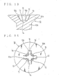
- a prior art screw 10 shown in Fig.13 is provided, on a screw head portion 10a thereof, with crossed flutes 12.
- the crossed flutes 12 are provided with constantly inclined flute portions 12a, each extending from the end portion towards the central portion of a screw neck portion 10b.
- the crossed flutes 12 are also provided, on a bottom portion thereof, with a substantially conical bottom surface 14 inclined gradually.
- reference numeral 13 designates tapered sidewall portions formed between adjacent crossed flutes 12. That is, the tapered sidewall portions 13 engageably contact with the blade portions of a driver bit, which is described later.
- a prior art driver bit 20 shown in Fig. 15 is provided with blade portions 22 to fit the crossed flutes 12 of the aforementioned screw 10.
- the driver bit 20 is also provided with extended blade portions 22a each extended so as to fit the shape of the inclined flute portions 12a that are formed to orient towards the central portion of the screw neck portion 10b from the end portions of the aforementioned crossed flutes 12.
- reference numeral 23 designates tapered sidewall portions that are formed on the both sides of the aforementioned respective blade portions 22 or extended blade portions 22a. That is, the tapered sidewall portions 23 engageably contact with the tapered sidewall portions 13 formed in the crossed flutes 12 of the aforementioned screw 10.
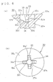
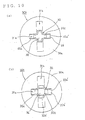
- the horizontal stepped portions 32b or non-planar bottom portions 32b are formed at the bit mate flutes 32 of the screw 30.
- the contact area of the sidewall portions 33 of the bit mate flutes 32 which is brought into contact with the wing portions 42 of the driver bit 40 or the sidewall portions 43 of the flat blade portions 42 can thereby be increased.
- the tapered contact area in which the inclined flute portions 32c of the bit mate flutes 32 of the screw 30 are brought into contact with the extended wing portions 42b or the projections 42b of the driver bit 40 is only partial and small. Accordingly, the come-out phenomenon that occurs in the combination of a prior art screw and a driver bit can be positively prevented.
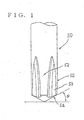
- the driver bit according to the present invention is a driver bit fit for a screw with substantially vertical end wall portions of a predetermined depth, the wall portions being formed at end portions of bit mate flutes of a screw head portion, with substantially planar bottom portions formed to orient towards a central portion of a screw neck portion from lower rim portions of the vertical end wall portions, and with a conical bottom surface formed at the central portion thereof, the aforementioned driver bit characterized by comprising flat blade portions having substantially vertical end portions for fitting a distal end portion thereof into the bit mate flutes of the screw head portion along the vertical end wall portions, wherein a distal end face of the flat blade portions is formed as a conical projected portion inclined at an angle of from 1° to 45° relative to the horizontal.
- the wall portions formed at the end portions of the bit mate flutes can be recessed substantially in the shape of " ⁇ " in cross section.
- the present invention is characterized by combining the driver bit and a plus/minus screw in which a screw head portion is provided with bit mate flutes composed of crossed flutes; one of straight flutes of the crossed bit mate flutes is so formed as to allow blade portions of a plus driver bit to fit therein; the other straight flute is so formed as to allow blade portions of a minus driver bit to fit therein; and substantially vertical end wall portions of a predetermined depth are formed at end portions of the aforementioned one of the straight flutes.
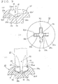
- reference numeral 53 designates sidewall portions formed on the both side faces of the aforementioned flat blade portion 52 substantially vertically and permitted to be slightly tapered. Accordingly, the sidewall portions 53 are engageably brought into contact with sidewall portions 33 formed in the bit mate flutes 32 of the aforementioned screw 30. Accordingly, these driving faces will be provided with a sufficiently wide engagement area, thus preventing effectively the come-out phenomenon caused by the combination of a conventional screw and driver bit.
- the aforementioned driver bit 50 when a typical plus driver bit is used to damage the opening portion side of the bit mate flutes 32 in screwing or unscrewing, the aforementioned driver bit 50 can be used to remove the cut particles stacked in the bit mate flutes 32 by pushing them into the gap portion G. At the same time, the aforementioned driver bit 50 achieves appropriate mating between the bottom portion side of the bit mate flutes 32 and the distal end of the blade portion of the driver bit 50, thus allowing screwing or unscrewing to be completed.
Landscapes
- Engineering & Computer Science (AREA)
- General Engineering & Computer Science (AREA)
- Mechanical Engineering (AREA)
- Details Of Spanners, Wrenches, And Screw Drivers And Accessories (AREA)
- Dowels (AREA)
- Earth Drilling (AREA)
- Connection Of Plates (AREA)
- Joining Of Building Structures In Genera (AREA)
- Hand Tools For Fitting Together And Separating, Or Other Hand Tools (AREA)
- Gripping Jigs, Holding Jigs, And Positioning Jigs (AREA)
- Perforating, Stamping-Out Or Severing By Means Other Than Cutting (AREA)
- Surgical Instruments (AREA)
Applications Claiming Priority (7)
| Application Number | Priority Date | Filing Date | Title |
|---|---|---|---|
| JP04225098A JP4197546B2 (ja) | 1998-02-24 | 1998-02-24 | ねじ及びドライバービットとの組合せ |
| JP4225098 | 1998-02-24 | ||
| JP11573998 | 1998-04-24 | ||
| JP11573998A JPH11311226A (ja) | 1998-04-24 | 1998-04-24 | ねじ及びドライバービットとの組合せ |
| JP27624898 | 1998-09-29 | ||
| JP27624898A JP4394184B2 (ja) | 1998-09-29 | 1998-09-29 | ドライバービット及びねじとの組合せ |
| EP99903935A EP1080846B1 (de) | 1998-02-24 | 1999-02-23 | Schraubenziehereinsatz und dessen kombination mit einer schraube |
Related Parent Applications (1)
| Application Number | Title | Priority Date | Filing Date |
|---|---|---|---|
| EP99903935A Division EP1080846B1 (de) | 1998-02-24 | 1999-02-23 | Schraubenziehereinsatz und dessen kombination mit einer schraube |
Publications (3)
| Publication Number | Publication Date |
|---|---|
| EP1493536A2 true EP1493536A2 (de) | 2005-01-05 |
| EP1493536A3 EP1493536A3 (de) | 2005-07-13 |
| EP1493536B1 EP1493536B1 (de) | 2006-11-15 |
Family
ID=27291133
Family Applications (2)
| Application Number | Title | Priority Date | Filing Date |
|---|---|---|---|
| EP04023163A Expired - Lifetime EP1493536B1 (de) | 1998-02-24 | 1999-02-23 | Kombination aus Schraube und Schraubenzieherklinge |
| EP99903935A Expired - Lifetime EP1080846B1 (de) | 1998-02-24 | 1999-02-23 | Schraubenziehereinsatz und dessen kombination mit einer schraube |
Family Applications After (1)
| Application Number | Title | Priority Date | Filing Date |
|---|---|---|---|
| EP99903935A Expired - Lifetime EP1080846B1 (de) | 1998-02-24 | 1999-02-23 | Schraubenziehereinsatz und dessen kombination mit einer schraube |
Country Status (10)
| Country | Link |
|---|---|
| US (1) | US6378406B1 (de) |
| EP (2) | EP1493536B1 (de) |
| KR (1) | KR100563626B1 (de) |
| CN (1) | CN1130276C (de) |
| AT (2) | ATE314904T1 (de) |
| AU (1) | AU752248B2 (de) |
| CA (1) | CA2321711C (de) |
| DE (2) | DE69934032T2 (de) |
| TW (1) | TW399126B (de) |
| WO (1) | WO1999043472A1 (de) |
Families Citing this family (30)
| Publication number | Priority date | Publication date | Assignee | Title |
|---|---|---|---|---|
| JP4493135B2 (ja) * | 2000-01-06 | 2010-06-30 | 勝行 戸津 | ねじとドライバービットの組合せ |
| JP4731054B2 (ja) * | 2001-06-29 | 2011-07-20 | 勝行 戸津 | ねじ及びドライバービットとの組合せ並びにねじ製造用ヘッダーパンチ |
| JP4197599B2 (ja) | 2002-03-12 | 2008-12-17 | 勝行 戸津 | いじり防止ねじ及びドライバービットとの組合せ並びにいじり防止ねじ製造用ヘッダーパンチ |
| JP4280457B2 (ja) * | 2002-04-18 | 2009-06-17 | 勝行 戸津 | ねじ保持形ドライバービット及びねじとの組合せ |
| JP2005106269A (ja) * | 2003-01-20 | 2005-04-21 | Syouei Screw Co Ltd | ねじ及びドライバビット並びにねじ頭部形成用パンチ |
| US20050249573A1 (en) * | 2003-01-21 | 2005-11-10 | Bernard Tanner | Screw and corresponding driver |
| US20070082526A1 (en) * | 2003-01-21 | 2007-04-12 | Bernard Tanner | Screwdriver Bit and Mating Socket |
| DE10310410A1 (de) * | 2003-03-07 | 2004-09-23 | Robert Schröder GmbH & Co. KG | Schraubendreherwerkzeug |
| JP4823692B2 (ja) * | 2003-11-14 | 2011-11-24 | 勝行 戸津 | 強度安定型ねじ及びドライバービットとの組合せ |
| FR2866084B1 (fr) * | 2004-02-11 | 2007-11-02 | Legrand Sa | Vis de fixation comprenant une tete a empreinte mixte pour outils de manoeuvre plat et cruciforme |
| US7322265B2 (en) * | 2006-01-09 | 2008-01-29 | Chen Hang-Hui | Compound screwdriver head |
| US7311026B2 (en) * | 2006-02-21 | 2007-12-25 | Joshua Robert Melton | Strip resistant screw head and screwdriver tip in combination |
| US20070207009A1 (en) * | 2006-03-06 | 2007-09-06 | Teng-Hung Lin | Screw with a recess in the head of the screw |
| JP5303080B2 (ja) * | 2007-06-27 | 2013-10-02 | 輝文 野地川 | ねじおよびドライバビット |
| JP5021599B2 (ja) | 2008-10-10 | 2012-09-12 | クラウン精密工業株式会社 | 螺子におけるドライバービット嵌合用十字溝の構造 |
| WO2010091281A1 (en) * | 2009-02-05 | 2010-08-12 | Milwaukee Electric Tool Corporation | Screwdriver |
| US8621961B2 (en) * | 2009-04-28 | 2014-01-07 | Milwaukee Electric Tool Corporation | Multi-purpose tool |
| USD754513S1 (en) | 2010-02-05 | 2016-04-26 | Milwaukee Electric Tool Corporation | Screwdriver head |
| JP5060582B2 (ja) * | 2010-04-16 | 2012-10-31 | 日東精工株式会社 | ねじ部品の駆動穴 |
| CA2804390C (en) | 2010-07-07 | 2019-01-08 | Infastech Intellectual Properties Pte. Ltd. | Torque transmission driver |
| US10968939B2 (en) | 2011-08-25 | 2021-04-06 | Infastech Intellectual Properties Pte. Ltd. | Tapered lobular driver and fastener |
| CA3104143C (en) | 2011-08-25 | 2023-08-22 | Infastech Intellectual Properties Pte. Ltd. | Tapered lobular driver and fastener |
| EP2932929B1 (de) * | 2014-04-15 | 2017-02-08 | Biedermann Technologies GmbH & Co. KG | Schraubelement zur Verwendung in der spinalen, orthopädischen oder traumatologischen Chirurgie und System mit solch einem Schraubelement und daran angepassten Schraubendreher |
| US9044843B1 (en) | 2014-05-07 | 2015-06-02 | David Mokhtee | Strip resistant screw and rescue driver |
| CN107000176B (zh) * | 2014-09-11 | 2020-11-06 | 英法斯泰克知识产权私人有限公司 | 锥形带凸角驱动器及紧固件 |
| TWI807482B (zh) * | 2017-03-23 | 2023-07-01 | 美商葛利普控股公司 | 多夾持點套筒起子頭 |
| US10941491B2 (en) * | 2017-09-25 | 2021-03-09 | Raytheon Technologies Corporation | Continuous multiple tow coating reactor |
| USD897806S1 (en) * | 2018-04-30 | 2020-10-06 | William Norton | Driver |
| TWI704982B (zh) * | 2019-12-03 | 2020-09-21 | 鴻安國際興業有限公司 | 具有防滑功能的驅動工具 |
| US20220297270A1 (en) * | 2021-03-18 | 2022-09-22 | William Norton | Driver Having Helical Toothed Blades |
Family Cites Families (25)
| Publication number | Priority date | Publication date | Assignee | Title |
|---|---|---|---|---|
| US2216382A (en) * | 1939-11-01 | 1940-10-01 | W H Holmes | Screw |
| FR1308935A (fr) * | 1961-12-27 | 1962-11-09 | Tournevis cruciforme | |
| US3234982A (en) * | 1963-06-24 | 1966-02-15 | Gardner Denver Co | Driver for recessed head fasteners |
| US3575080A (en) * | 1968-12-02 | 1971-04-13 | Patrick M Hannay | Fastener wrenching means |
| SE362817B (de) * | 1971-03-25 | 1973-12-27 | T L Hill | |
| US3894450A (en) * | 1971-03-25 | 1975-07-15 | Tore L Hill | Combined screw driving and screw gripping tool |
| JPS4958955U (de) * | 1972-09-08 | 1974-05-24 | ||
| JPS4958955A (de) | 1972-10-13 | 1974-06-07 | ||
| JPS49150998U (de) * | 1973-04-26 | 1974-12-27 | ||
| US4151621A (en) * | 1974-09-12 | 1979-05-01 | Phillips Screw Company | Tools for punching fastener heads |
| DE8114236U1 (de) * | 1980-05-20 | 1981-09-24 | Julius Blum Gesellschaft mbH, 6973 Höchst | Drehelement, insbesondere Schraube |
| GB2188389A (en) * | 1985-11-30 | 1987-09-30 | Clive Alan Newbould | Screw driving formations |
| JPH0799523B2 (ja) | 1986-11-05 | 1995-10-25 | 株式会社日立製作所 | 伝票・通帳印字処理方法 |
| JPS63116272U (de) * | 1987-01-26 | 1988-07-27 | ||
| JPH0714999B2 (ja) | 1987-11-27 | 1995-02-22 | 三ツ星ベルト株式会社 | ポリアミド樹脂成形体の製造方法 |
| JPH01141914U (de) * | 1988-03-24 | 1989-09-28 | ||
| JP3063093B2 (ja) | 1989-07-20 | 2000-07-12 | 日本電気株式会社 | 無限移相器 |
| JPH0353611U (de) * | 1989-10-02 | 1991-05-23 | ||
| AT398231B (de) * | 1991-06-04 | 1994-10-25 | Cvetkovic Mirko | Schraubenkopf mit schlitzen |
| DE4300446C2 (de) * | 1992-12-22 | 2002-12-19 | Werner Hermann Wera Werke | Schraubwerkzeug, insbesondere Schraubendrehereinsatz |
| US5370021A (en) * | 1993-05-13 | 1994-12-06 | Eight Co., Ltd. | Polygon headed wrench |
| JP3863924B2 (ja) * | 1994-11-16 | 2006-12-27 | 勝行 戸津 | ねじとドライバービットの組合せ |
| JP3671080B2 (ja) | 1995-12-22 | 2005-07-13 | 勝行 戸津 | ねじ及びドライバービット並にねじ製造用ヘッダーパンチ |
| US5660091A (en) * | 1996-02-06 | 1997-08-26 | Walter Lorenz Surgical, Inc. | Blunt-nosed, self-retaining screwdriver |
| US6223634B1 (en) * | 1997-10-03 | 2001-05-01 | Phillips Screw Company | Recessed head fastener and driver systems |
-
1999
- 1999-02-23 AT AT99903935T patent/ATE314904T1/de not_active IP Right Cessation
- 1999-02-23 WO PCT/JP1999/000817 patent/WO1999043472A1/ja not_active Ceased
- 1999-02-23 CN CN99803241A patent/CN1130276C/zh not_active Expired - Lifetime
- 1999-02-23 AU AU24412/99A patent/AU752248B2/en not_active Ceased
- 1999-02-23 EP EP04023163A patent/EP1493536B1/de not_active Expired - Lifetime
- 1999-02-23 CA CA002321711A patent/CA2321711C/en not_active Expired - Fee Related
- 1999-02-23 US US09/622,865 patent/US6378406B1/en not_active Expired - Lifetime
- 1999-02-23 EP EP99903935A patent/EP1080846B1/de not_active Expired - Lifetime
- 1999-02-23 AT AT04023163T patent/ATE345197T1/de not_active IP Right Cessation
- 1999-02-23 DE DE69934032T patent/DE69934032T2/de not_active Expired - Lifetime
- 1999-02-23 KR KR1020007009158A patent/KR100563626B1/ko not_active Expired - Lifetime
- 1999-02-23 DE DE69929304T patent/DE69929304T2/de not_active Expired - Lifetime
- 1999-04-23 TW TW088106482A patent/TW399126B/zh active
Also Published As
| Publication number | Publication date |
|---|---|
| CA2321711C (en) | 2007-12-11 |
| TW399126B (en) | 2000-07-21 |
| CN1291931A (zh) | 2001-04-18 |
| AU752248B2 (en) | 2002-09-12 |
| ATE345197T1 (de) | 2006-12-15 |
| WO1999043472A1 (en) | 1999-09-02 |
| ATE314904T1 (de) | 2006-02-15 |
| DE69934032T2 (de) | 2007-06-06 |
| DE69929304T2 (de) | 2006-08-31 |
| EP1080846A4 (de) | 2002-05-15 |
| DE69929304D1 (de) | 2006-03-30 |
| CA2321711A1 (en) | 1999-09-02 |
| AU2441299A (en) | 1999-09-15 |
| KR20010041117A (ko) | 2001-05-15 |
| EP1493536A3 (de) | 2005-07-13 |
| EP1080846A1 (de) | 2001-03-07 |
| US6378406B1 (en) | 2002-04-30 |
| EP1080846B1 (de) | 2006-01-04 |
| EP1493536B1 (de) | 2006-11-15 |
| CN1130276C (zh) | 2003-12-10 |
| KR100563626B1 (ko) | 2006-03-22 |
| DE69934032D1 (de) | 2006-12-28 |
| HK1036245A1 (en) | 2001-12-28 |
Similar Documents
| Publication | Publication Date | Title |
|---|---|---|
| EP1080846B1 (de) | Schraubenziehereinsatz und dessen kombination mit einer schraube | |
| US6341546B1 (en) | Screw, driver bit and header punch for manufacture of screw | |
| KR100774095B1 (ko) | 나사와 드라이버 비트의 조합 및 그 제조용 헤더펀치 | |
| EP1010900B1 (de) | Schraube mit Vertiefung und Schraubenziehereinsatz hierfür | |
| US6843729B2 (en) | Fastener having recess useable with multiple drivers and method of manufacture | |
| US7077038B2 (en) | Screw having non-strip drive recess and driver bit for use with the screw | |
| JP4731054B2 (ja) | ねじ及びドライバービットとの組合せ並びにねじ製造用ヘッダーパンチ | |
| KR101234369B1 (ko) | 강도 안정형 나사와 드라이버 비트의 조합체 | |
| JP3863924B2 (ja) | ねじとドライバービットの組合せ | |
| JP4394184B2 (ja) | ドライバービット及びねじとの組合せ | |
| JP3671080B2 (ja) | ねじ及びドライバービット並にねじ製造用ヘッダーパンチ | |
| JPH10131930A (ja) | プラマイねじ及びドライバービットとの組合せ | |
| JPH11311226A (ja) | ねじ及びドライバービットとの組合せ | |
| JP4197546B2 (ja) | ねじ及びドライバービットとの組合せ | |
| JPH10202545A (ja) | プラマイねじ用ドライバービット | |
| HK1036245B (en) | Combination of driver bit and screw |
Legal Events
| Date | Code | Title | Description |
|---|---|---|---|
| PUAI | Public reference made under article 153(3) epc to a published international application that has entered the european phase |
Free format text: ORIGINAL CODE: 0009012 |
|
| AC | Divisional application: reference to earlier application |
Ref document number: 1080846 Country of ref document: EP Kind code of ref document: P |
|
| AK | Designated contracting states |
Kind code of ref document: A2 Designated state(s): AT BE CH CY DE DK ES FI FR GB GR IE IT LI LU MC NL PT SE |
|
| PUAL | Search report despatched |
Free format text: ORIGINAL CODE: 0009013 |
|
| AK | Designated contracting states |
Kind code of ref document: A3 Designated state(s): AT BE CH CY DE DK ES FI FR GB GR IE IT LI LU MC NL PT SE |
|
| 17P | Request for examination filed |
Effective date: 20050726 |
|
| AKX | Designation fees paid |
Designated state(s): AT BE CH CY DE DK ES FI FR GB GR IE IT LI LU MC NL PT SE |
|
| GRAP | Despatch of communication of intention to grant a patent |
Free format text: ORIGINAL CODE: EPIDOSNIGR1 |
|
| GRAS | Grant fee paid |
Free format text: ORIGINAL CODE: EPIDOSNIGR3 |
|
| GRAA | (expected) grant |
Free format text: ORIGINAL CODE: 0009210 |
|
| AC | Divisional application: reference to earlier application |
Ref document number: 1080846 Country of ref document: EP Kind code of ref document: P |
|
| AK | Designated contracting states |
Kind code of ref document: B1 Designated state(s): AT BE CH CY DE DK ES FI FR GB GR IE IT LI LU MC NL PT SE |
|
| PG25 | Lapsed in a contracting state [announced via postgrant information from national office to epo] |
Ref country code: AT Free format text: LAPSE BECAUSE OF FAILURE TO SUBMIT A TRANSLATION OF THE DESCRIPTION OR TO PAY THE FEE WITHIN THE PRESCRIBED TIME-LIMIT Effective date: 20061115 Ref country code: BE Free format text: LAPSE BECAUSE OF FAILURE TO SUBMIT A TRANSLATION OF THE DESCRIPTION OR TO PAY THE FEE WITHIN THE PRESCRIBED TIME-LIMIT Effective date: 20061115 Ref country code: NL Free format text: LAPSE BECAUSE OF FAILURE TO SUBMIT A TRANSLATION OF THE DESCRIPTION OR TO PAY THE FEE WITHIN THE PRESCRIBED TIME-LIMIT Effective date: 20061115 |
|
| REG | Reference to a national code |
Ref country code: GB Ref legal event code: FG4D |
|
| REG | Reference to a national code |
Ref country code: CH Ref legal event code: EP |
|
| REF | Corresponds to: |
Ref document number: 69934032 Country of ref document: DE Date of ref document: 20061228 Kind code of ref document: P |
|
| REG | Reference to a national code |
Ref country code: IE Ref legal event code: FG4D |
|
| REG | Reference to a national code |
Ref country code: SE Ref legal event code: TRGR |
|
| PG25 | Lapsed in a contracting state [announced via postgrant information from national office to epo] |
Ref country code: DK Free format text: LAPSE BECAUSE OF FAILURE TO SUBMIT A TRANSLATION OF THE DESCRIPTION OR TO PAY THE FEE WITHIN THE PRESCRIBED TIME-LIMIT Effective date: 20070215 |
|
| REG | Reference to a national code |
Ref country code: CH Ref legal event code: NV Representative=s name: NOVAGRAAF INTERNATIONAL SA |
|
| PG25 | Lapsed in a contracting state [announced via postgrant information from national office to epo] |
Ref country code: ES Free format text: LAPSE BECAUSE OF FAILURE TO SUBMIT A TRANSLATION OF THE DESCRIPTION OR TO PAY THE FEE WITHIN THE PRESCRIBED TIME-LIMIT Effective date: 20070226 |
|
| PG25 | Lapsed in a contracting state [announced via postgrant information from national office to epo] |
Ref country code: MC Free format text: LAPSE BECAUSE OF NON-PAYMENT OF DUE FEES Effective date: 20070228 |
|
| PG25 | Lapsed in a contracting state [announced via postgrant information from national office to epo] |
Ref country code: PT Free format text: LAPSE BECAUSE OF FAILURE TO SUBMIT A TRANSLATION OF THE DESCRIPTION OR TO PAY THE FEE WITHIN THE PRESCRIBED TIME-LIMIT Effective date: 20070416 |
|
| NLV1 | Nl: lapsed or annulled due to failure to fulfill the requirements of art. 29p and 29m of the patents act | ||
| ET | Fr: translation filed | ||
| PLBE | No opposition filed within time limit |
Free format text: ORIGINAL CODE: 0009261 |
|
| STAA | Information on the status of an ep patent application or granted ep patent |
Free format text: STATUS: NO OPPOSITION FILED WITHIN TIME LIMIT |
|
| 26N | No opposition filed |
Effective date: 20070817 |
|
| PG25 | Lapsed in a contracting state [announced via postgrant information from national office to epo] |
Ref country code: IE Free format text: LAPSE BECAUSE OF NON-PAYMENT OF DUE FEES Effective date: 20070223 |
|
| PG25 | Lapsed in a contracting state [announced via postgrant information from national office to epo] |
Ref country code: GR Free format text: LAPSE BECAUSE OF FAILURE TO SUBMIT A TRANSLATION OF THE DESCRIPTION OR TO PAY THE FEE WITHIN THE PRESCRIBED TIME-LIMIT Effective date: 20070216 |
|
| PG25 | Lapsed in a contracting state [announced via postgrant information from national office to epo] |
Ref country code: LU Free format text: LAPSE BECAUSE OF NON-PAYMENT OF DUE FEES Effective date: 20070223 Ref country code: CY Free format text: LAPSE BECAUSE OF FAILURE TO SUBMIT A TRANSLATION OF THE DESCRIPTION OR TO PAY THE FEE WITHIN THE PRESCRIBED TIME-LIMIT Effective date: 20061115 |
|
| PGFP | Annual fee paid to national office [announced via postgrant information from national office to epo] |
Ref country code: CH Payment date: 20100122 Year of fee payment: 12 |
|
| PGFP | Annual fee paid to national office [announced via postgrant information from national office to epo] |
Ref country code: IT Payment date: 20100128 Year of fee payment: 12 Ref country code: FR Payment date: 20100311 Year of fee payment: 12 Ref country code: FI Payment date: 20100219 Year of fee payment: 12 |
|
| PGFP | Annual fee paid to national office [announced via postgrant information from national office to epo] |
Ref country code: GB Payment date: 20100201 Year of fee payment: 12 |
|
| PGFP | Annual fee paid to national office [announced via postgrant information from national office to epo] |
Ref country code: SE Payment date: 20100216 Year of fee payment: 12 |
|
| REG | Reference to a national code |
Ref country code: CH Ref legal event code: PFA Owner name: TOTSU, KATSUYUKI Free format text: TOTSU, KATSUYUKI#32-13, OSHIAGE 1-CHOME, SUMIDA-KU#TOKYO 131-0045 (JP) -TRANSFER TO- TOTSU, KATSUYUKI#32-13, OSHIAGE 1-CHOME, SUMIDA-KU#TOKYO 131-0045 (JP) |
|
| REG | Reference to a national code |
Ref country code: CH Ref legal event code: PL |
|
| REG | Reference to a national code |
Ref country code: SE Ref legal event code: EUG |
|
| GBPC | Gb: european patent ceased through non-payment of renewal fee |
Effective date: 20110223 |
|
| PG25 | Lapsed in a contracting state [announced via postgrant information from national office to epo] |
Ref country code: CH Free format text: LAPSE BECAUSE OF NON-PAYMENT OF DUE FEES Effective date: 20110228 Ref country code: LI Free format text: LAPSE BECAUSE OF NON-PAYMENT OF DUE FEES Effective date: 20110228 |
|
| REG | Reference to a national code |
Ref country code: FR Ref legal event code: ST Effective date: 20111102 |
|
| PG25 | Lapsed in a contracting state [announced via postgrant information from national office to epo] |
Ref country code: FI Free format text: LAPSE BECAUSE OF NON-PAYMENT OF DUE FEES Effective date: 20110223 |
|
| PG25 | Lapsed in a contracting state [announced via postgrant information from national office to epo] |
Ref country code: IT Free format text: LAPSE BECAUSE OF NON-PAYMENT OF DUE FEES Effective date: 20110223 |
|
| PG25 | Lapsed in a contracting state [announced via postgrant information from national office to epo] |
Ref country code: FR Free format text: LAPSE BECAUSE OF NON-PAYMENT OF DUE FEES Effective date: 20110228 |
|
| PG25 | Lapsed in a contracting state [announced via postgrant information from national office to epo] |
Ref country code: GB Free format text: LAPSE BECAUSE OF NON-PAYMENT OF DUE FEES Effective date: 20110223 |
|
| PG25 | Lapsed in a contracting state [announced via postgrant information from national office to epo] |
Ref country code: SE Free format text: LAPSE BECAUSE OF NON-PAYMENT OF DUE FEES Effective date: 20110224 |
|
| PGFP | Annual fee paid to national office [announced via postgrant information from national office to epo] |
Ref country code: DE Payment date: 20180222 Year of fee payment: 20 |
|
| REG | Reference to a national code |
Ref country code: DE Ref legal event code: R071 Ref document number: 69934032 Country of ref document: DE |