EP1493601B1 - Toit de véhicule - Google Patents
Toit de véhicule Download PDFInfo
- Publication number
- EP1493601B1 EP1493601B1 EP04014922A EP04014922A EP1493601B1 EP 1493601 B1 EP1493601 B1 EP 1493601B1 EP 04014922 A EP04014922 A EP 04014922A EP 04014922 A EP04014922 A EP 04014922A EP 1493601 B1 EP1493601 B1 EP 1493601B1
- Authority
- EP
- European Patent Office
- Prior art keywords
- sliding element
- cover
- vehicle roof
- slotted guide
- slide
- Prior art date
- Legal status (The legal status is an assumption and is not a legal conclusion. Google has not performed a legal analysis and makes no representation as to the accuracy of the status listed.)
- Expired - Lifetime
Links
- 238000006073 displacement reaction Methods 0.000 claims description 10
- 230000008093 supporting effect Effects 0.000 claims description 4
- 230000003993 interaction Effects 0.000 claims description 3
- 230000000630 rising effect Effects 0.000 description 6
- 230000007246 mechanism Effects 0.000 description 4
- 230000007704 transition Effects 0.000 description 3
- 239000007787 solid Substances 0.000 description 2
- 230000000977 initiatory effect Effects 0.000 description 1
- 239000002991 molded plastic Substances 0.000 description 1
- 239000004033 plastic Substances 0.000 description 1
- 238000007789 sealing Methods 0.000 description 1
Images


Classifications
-
- B—PERFORMING OPERATIONS; TRANSPORTING
- B60—VEHICLES IN GENERAL
- B60J—WINDOWS, WINDSCREENS, NON-FIXED ROOFS, DOORS, OR SIMILAR DEVICES FOR VEHICLES; REMOVABLE EXTERNAL PROTECTIVE COVERINGS SPECIALLY ADAPTED FOR VEHICLES
- B60J7/00—Non-fixed roofs; Roofs with movable panels, e.g. rotary sunroofs
- B60J7/02—Non-fixed roofs; Roofs with movable panels, e.g. rotary sunroofs of sliding type, e.g. comprising guide shoes
- B60J7/024—Non-fixed roofs; Roofs with movable panels, e.g. rotary sunroofs of sliding type, e.g. comprising guide shoes characterised by the height regulating mechanism of the sliding panel
-
- B—PERFORMING OPERATIONS; TRANSPORTING
- B60—VEHICLES IN GENERAL
- B60J—WINDOWS, WINDSCREENS, NON-FIXED ROOFS, DOORS, OR SIMILAR DEVICES FOR VEHICLES; REMOVABLE EXTERNAL PROTECTIVE COVERINGS SPECIALLY ADAPTED FOR VEHICLES
- B60J7/00—Non-fixed roofs; Roofs with movable panels, e.g. rotary sunroofs
- B60J7/02—Non-fixed roofs; Roofs with movable panels, e.g. rotary sunroofs of sliding type, e.g. comprising guide shoes
- B60J7/04—Non-fixed roofs; Roofs with movable panels, e.g. rotary sunroofs of sliding type, e.g. comprising guide shoes with rigid plate-like element or elements, e.g. open roofs with harmonica-type folding rigid panels
- B60J7/043—Sunroofs e.g. sliding above the roof
- B60J7/0435—Sunroofs e.g. sliding above the roof pivoting upwardly to vent mode and moving at the outside of the roof to fully open mode
Definitions
- the invention relates to a vehicle roof according to the preamble of patent claim 1.
- Such a vehicle roof with an externally guided lid is from the DE 197 13 347 A1 known.
- a movable by means of a drive cable carriage moves a lower pivot point of a deployment lever, which is guided in the middle with a sliding element in a stationary slide track and the upper end is slidably guided with a further sliding element in a slide track on a cover carrier.
- the support of the lid trailing edge during a displacement of the lid is taken over by a support lever, which is provided independently of the release lever.
- Such a mechanism requires because of the required transfer from the release lever to the support lever a very accurate production and assembly of all components involved and a large footprint in the width of the vehicle (Y-direction) seen.
- a similar generic vehicle roof is from the DE 101 40 389 A1 known.
- FIG. 1 Another vehicle roof, in which a first slide track for a front sliding element and a third slide track for a rear sliding element are arranged on a carriage and a second slide track on the guide rail, is from the EP 1 314 600 A1 known.
- the support in the front area takes place there by a single sliding element, which is in engagement with the first and second slide track.
- the support in the rear area is effected by a pivotable lever, which is in engagement with a sliding element with the third slide track.
- a vehicle roof in which a front pivot mechanism of a lid of two adjacent to each other formed on a carriage slide tracks and two engaging therein, arranged on a cover inner plate pins is formed.
- the object of the invention is to provide a vehicle roof, which ensures a narrow-building, simple and safe support of the lid in all phases of movement.
- the first and the second sliding element are arranged in the front region of the lid carrier.
- the movement of the lid leading edge can be controlled so that it lifts slightly when opening and is slightly displaced to the rear, so that no collision with the front seal occurs.
- the gate assembly comprises a third sliding element, which is guided in a third slide track.
- the third sliding element is arranged in the rear region of the lid carrier.
- the slide track for the first sliding element and the second sliding element cross in a preferred variant.
- the first sliding element and the second sliding element are formed in a particularly space-saving embodiment on different sides of the component carrying them.
- the lid can be both part of a solid vehicle roof and part of a convertible top, which is preferably constructed exclusively of solid elements.
- a fixed-element convertible is generally from the DE 197 13 347 C1 known.
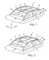
- FIG. 1 illustrated vehicle roof 1 is then placed on the upper edge of a windscreen 21 from a Windabweislamelle 2, a cover 3, a rear adjoining rear roof part 4, and from the Windabweislamelle 2 and the lid 3 laterally bounding side rails 6 and a rear roof cassette 19 together, which surrounds the rear roof part 4.
- the vehicle roof 1 is formed in this example as a fixed-element convertible, in which the cover 3 can be moved over the rear roof part 4 and in the after pivoting of the side rails 6, the package of cover 3, rear roof part 4, roof cassette 19 and C-pillars 18 can be stored in a storage space, not shown in the rear of the vehicle.
- the invention is also suitable for an externally guided lid 3 in a fixed vehicle roof.
- the optionally provided Windabweislamelle 2 is preferably independent of the position of the lid 3 in a fan position according to Fig. 2 issuable.
- the lid 3 is connected on both sides with a lid carrier 7, which is connected to the inside of the lid 3 and extends approximately at right angles vertically downwards near the lateral outer edges of the lid 3 (see Fig. 6 ).
- the lid carrier 7 is preferably used simultaneously with flared lid trailing edge as a side panel to cover the triangular side gap S (see Fig. 2 ).
- the cover 3 has at its outer edge a seal 16 for sealing engagement with the edge of the roof opening 5.
- the seal 16 can also, as shown, be attached to the edge of the roof opening 5, so that a molded-plastic edge 20 rests against the lid 3 on the seal 16.
- the cover carrier 7 On the cover carrier 7 a total of three sliding elements 8, 9, 10 are arranged.
- the three sliding elements 8, 9, 10 are each mounted rotatably by means of a pivot axis on the cover carrier 7. They are about the same height, d. H. arranged at the same distance from the lid 3 near the lower edge of the lid carrier 7.
- the first sliding element 8 is arranged behind a second sliding element 9 at a slight distance from it, while the third sliding element 10 is located approximately in the rear third of the cover 3.
- a carriage 11 is slidably guided in each case.
- the guide rail 15 has a guide channel 15 C.
- the carriage 11 is in a known manner by means of a him attached drive cable moves by means of an electric motor, not shown.
- the drive cable itself is not shown; it will be in the in 6 and 7 shown cable duct 15D tension and pressure rigid guided.
- a first slide track 12 is formed in the front region, in which the first sliding element 8 engages.
- the slide track 12 has a first approximately vertically disposed track section 12A, a downwardly adjoining curved track section 12B, an adjoining this rearwardly approximately horizontal track section 12C, an adjoining rearwardly sloping track section 12D and a lower approximately horizontal Track section 12E.
- a second slide track 13 is formed on the outer profile part 15B.
- the slide track 13 is composed of a front, steeply rising rearward rail portion 13A, a weaker rising rearward rail portion 13B and a rearwardly extending approximately horizontal track section 13C.
- a third slide track 14 is formed on this side facing the outer profile part 15B. This is composed from the back to the front of a lower, approximately horizontal track section 14A, a sloping forward sloping track section 14B and a front, approximately horizontal track section 14C together.
- the third sliding member 10 engages. When moving the Slider 11 backwards it passes through the track sections 14A, 14B and 14C.
- FIGS. 3 to 5 is the movement of the lid 3, starting from the closed position of the lid 3 in Fig. 3 , about the display position according to Fig. 4 up to the shift position according to Fig. 5 shown.
- the interaction of the sliding elements 8, 9 and 10 with the slide tracks 12, 13 and 14 becomes clear.
- the sliding elements 8, 9 and 10 are each guided so closely in their slide tracks 12, 13 and 14, that a curvature of a slide track forces the respective sliding element during a displacement of the carriage 11 a rotation.
- the first sliding member 8 is located at the rear end of the horizontal track section 12E of the first slide track 12.
- the second slide member 9 is at the lower end of the front track section 13A of the second slide track 13.
- the third slide member 10 is located at the rear end of the the rear track portion 14A of the third slide track 14.
- the cover 3 is supported in this position by the horizontally oriented by the web sections 12E and 14A sliding elements 8 and 10 in the vertical direction. It is simultaneously prevented by the due to the strong vertical course of the web portion 13 A of the second slide track 13 approximately vertically aligned second slider 9 to a rearward displacement.
- the first sliding element 8 passes through the slightly rising track section 12D and the approximately horizontally extending central track section 12C.
- the third slider 10 passes through the high-pitched track portion 14B and the initial portion of the approximately horizontal track portion 14C.
- the lid 3 is greatly raised with its trailing edge 3B, while the front edge 3A of the lid 3 is slightly raised, to avoid that the lid leading edge 3A immersed too much forward or down, with a seal in the region of the front edge of the roof opening 5 collided.
- the movements of the sliding elements are rather coordinated so that the cover leading edge 3A always remains in contact with this seal without compressing too much.
- the second sliding member 9 migrates in the front track section 13 A upwards, however, retains its predominantly vertical orientation, so that the cover 3 experiences only one of the Ausstellterrorism superimposed slight displacement to the rear, which is made possible by the inclination of the track section 13 A, the rest However, it is still blocked against displacement to the rear.
- the first sliding element 8 passes through the curved path section 12B, while the second sliding element 9 simultaneously passes through the rising path section 13B.
- the first sliding member 8 is thereby rotated from its horizontal position in which it supports the lid 3 in the vertical direction, in a vertical position in which it prevents a relative movement between the carriage 11 and the lid carrier 7 in the horizontal direction.
- the second sliding element 9 the more it is rotated from a predominantly vertical position to a more horizontal position, blocks the displacement of the cover carrier 7 towards the rear and at the same time more and more takes over the support of the cover 3 in the front region in the vertical direction.
- the first sliding member 8 is vertically at the upper end of the track portion 12A.
- the third slider 10 is located almost at the front end of the front track portion 14C.
- the second sliding member 9 slides in the horizontal path section 13C along the guide rail 15 to the rear.
- the two sliding elements 8 and 9 Due to the interaction of the two sliding elements 8 and 9 with the slide tracks 12 and 13 of the lid 3 in the closed position according to Fig. 3 and in the display position according to Fig. 4 secured by the sliding member 9 against displacement to the rear and simultaneously supported by the sliding member 8 in the vertical direction.
- the two sliding elements 8 and 9 change their role.
- the sliding element 9 takes over the vertical support of the lid 3 in the front region and the sliding element 8 locks the lid carrier 7 with the carriage 11, so that a forced entrainment of the lid 3 takes place to the rear.
Landscapes
- Engineering & Computer Science (AREA)
- Mechanical Engineering (AREA)
- Body Structure For Vehicles (AREA)
- Fittings On The Vehicle Exterior For Carrying Loads, And Devices For Holding Or Mounting Articles (AREA)
Claims (6)
- Toit de véhicule comprenant un couvercle (3), qui peut être sorti et coulissé avec son arête arrière (3B) dans la position sortie par un chariot (11) pouvant coulisser le long de rails de guidage (15) et coopérant avec un support de couvercle (7) connecté au couvercle (3) par le biais d'un agencement de coulisse, qui présente au moins une piste à coulisse (12, 13, 14) et un coulisseau (8, 9, 10) venant en prise dans celle-ci, l'agencement de coulisse présentant deux pistes à coulisse (12, 13) et deux coulisseaux (8, 9) venant en prise dans celles-ci, qui sont disposés dans la région avant du support de couvercle (7) et qui sont formés et disposés de telle sorte que dans le cas d'un déplacement du chariot (11), d'abord un premier coulisseau (8) assure un support du couvercle (3) dans la direction de la hauteur du toit du véhicule (direction Z), tandis qu'un deuxième coulisseau (9) exerce essentiellement un support dans la direction longitudinale du véhicule (direction X), et de telle sorte que lors du coulissement poursuivi du chariot (11), il se produise une inversion de l'effet de support des deux coulisseaux (8 et 9), la piste à coulisse (12) pour le premier coulisseau (8) étant réalisée sur le chariot (11) et la piste à coulisse (13) pour le deuxième coulisseau (9) étant réalisée sur le rail de guidage (15), et l'agencement de coulisse comprenant un troisième coulisseau (10), qui est guidé dans une troisième piste à coulisse (14), caractérisé en ce que la troisième piste à coulisse (14) est réalisée sur le chariot (11) et en ce que les trois coulisseaux (8, 9, 10) sont montés de manière rotative sur le support de couvercle (7).
- Toit de véhicule selon l'une quelconque des revendications précédentes, caractérisé en ce que les pistes à coulisse (12 et 13) pour le premier coulisseau (8) et le deuxième coulisseau (9) se croisent dans une projection dans la direction Y, c'est-à-dire dans la direction transversale du véhicule.
- Toit de véhicule selon la revendication 1 ou 2, caractérisé en ce que le troisième coulisseau (10) est disposé dans la région arrière du support de couvercle (7).
- Toit de véhicule selon l'une quelconque des revendications 1 à 3, caractérisé en ce que le premier coulisseau (8) et le deuxième coulisseau (9) sont réalisés sur des côtés différents du composant (7) qui les porte.
- Toit de véhicule selon l'une quelconque des revendications 1 à 4, caractérisé en ce que les rails de guidage (15) sont disposés sur des longerons latéraux déplaçables (6) d'une capote de cabriolet, et le couvercle (3) peut être abaissé après un coulissement complet vers l'arrière en tant que partie d'un module de capote complet (3, 4, 6, 18) .
- Toit de véhicule selon l'une quelconque des revendications précédentes, caractérisé en ce que le support de couvercle (7) est formé de telle sorte qu'il ferme au moins essentiellement, en tant que bandeau latéral, la fente triangulaire (S) produite lorsque le couvercle (3) est sorti.
Applications Claiming Priority (2)
| Application Number | Priority Date | Filing Date | Title |
|---|---|---|---|
| DE10329536A DE10329536B4 (de) | 2003-06-30 | 2003-06-30 | Fahrzeugdach |
| DE10329536 | 2003-06-30 |
Publications (3)
| Publication Number | Publication Date |
|---|---|
| EP1493601A2 EP1493601A2 (fr) | 2005-01-05 |
| EP1493601A3 EP1493601A3 (fr) | 2006-07-26 |
| EP1493601B1 true EP1493601B1 (fr) | 2009-09-23 |
Family
ID=33426801
Family Applications (1)
| Application Number | Title | Priority Date | Filing Date |
|---|---|---|---|
| EP04014922A Expired - Lifetime EP1493601B1 (fr) | 2003-06-30 | 2004-06-25 | Toit de véhicule |
Country Status (3)
| Country | Link |
|---|---|
| US (1) | US7044539B2 (fr) |
| EP (1) | EP1493601B1 (fr) |
| DE (2) | DE10329536B4 (fr) |
Families Citing this family (15)
| Publication number | Priority date | Publication date | Assignee | Title |
|---|---|---|---|---|
| US20060202007A1 (en) * | 2003-08-12 | 2006-09-14 | Jeremy Cohen | Foldable box or tray |
| DE10354832A1 (de) * | 2003-11-24 | 2005-06-23 | Arvinmeritor Gmbh | Verstellmechanik für ein Schiebe-/Hub-Dach |
| DE102004034463A1 (de) * | 2004-07-16 | 2006-02-16 | Arvinmeritor Gmbh | Schiebedachsystem für ein Kraftfahrzeug |
| DE102005051768B3 (de) * | 2005-10-27 | 2007-03-15 | Webasto Ag | Fahrzeug mit einem öffnungsfähigen Fahrzeugdach |
| EP1834820A1 (fr) * | 2006-03-13 | 2007-09-19 | ArvinMeritor GmbH | Toit panoramique |
| CA2652818A1 (fr) * | 2006-05-24 | 2007-12-06 | The Dial Corporation | Composition et methode destinees a lutter contre la transmission de norovirus |
| DE102008024948B4 (de) * | 2008-05-23 | 2010-04-08 | Webasto Ag | Bauraumoptimierte Antriebsmechanik für Deckelelement |
| FR2967942B1 (fr) * | 2010-11-26 | 2013-03-22 | Acs France Sas | Pavillon vitre a panneau mobile coulissant et entrebaillant |
| EP2457756B1 (fr) * | 2010-11-26 | 2015-08-12 | Advanced Comfort Systems France SAS - ACS France | Pavillon vitré à panneau mobile coulissant et entrebâillant |
| US20140005273A1 (en) | 2012-06-29 | 2014-01-02 | Ecolab Usa Inc. | Glycerin ether ethoxylate solfactants |
| JP5631944B2 (ja) * | 2012-08-22 | 2014-11-26 | 八千代工業株式会社 | サンルーフ装置 |
| JP6103196B2 (ja) * | 2013-01-23 | 2017-03-29 | アイシン精機株式会社 | ルーフ装置 |
| DE102014111539B4 (de) * | 2014-05-14 | 2015-12-31 | Webasto SE | Anordnung mit einem Deckel für ein Fahrzeugdach |
| DE102014110234A1 (de) * | 2014-05-14 | 2015-11-19 | Webasto SE | Anordnung mit einem Deckel für ein Fahrzeugdach |
| DE102024115823A1 (de) * | 2024-06-06 | 2025-12-11 | Webasto SE | Anordnung für ein Fahrzeugdach und Fahrzeugdach |
Family Cites Families (13)
| Publication number | Priority date | Publication date | Assignee | Title |
|---|---|---|---|---|
| DE3442616A1 (de) * | 1984-11-22 | 1986-05-28 | Daimler-Benz Ag, 7000 Stuttgart | Schiebehebedach |
| DE3920372C1 (fr) * | 1989-06-22 | 1990-08-02 | Webasto Ag Fahrzeugtechnik, 8035 Stockdorf, De | |
| DE4203229C2 (de) * | 1992-02-05 | 1994-07-21 | Webasto Karosseriesysteme | Fahrzeugdach |
| US5558388A (en) * | 1992-02-05 | 1996-09-24 | Webasto Karosseriesysteme Gmbh | Vehicle roof |
| EP0863817B1 (fr) * | 1996-10-01 | 2003-07-30 | WEBASTO KAROSSERIESYSTEME GmbH | Toit de vehicule avec au moins un couvercle |
| DE19713347C5 (de) * | 1997-03-29 | 2005-12-22 | Webasto Ag | Fahrzeugdach mit wenigstens einem oberhalb des festen Fahrzeugdachs verschiebbaren Deckel |
| FR2797225B1 (fr) * | 1999-08-02 | 2002-06-07 | Webasto Systemes Carrosserie | Dispositif pour ouvrir ou fermer un panneau exterieur mobile de toit ouvrant entrebaillant et coulissant |
| DE10046129C2 (de) * | 2000-09-15 | 2002-10-24 | Webasto Vehicle Sys Int Gmbh | Öffnungsfähiges Fahrzeugdach |
| DE10296880T5 (de) | 2001-05-29 | 2004-07-01 | Asc Inc., Southgate | Dachsystem für ein Kraftfahrzeug |
| DE10140389C2 (de) | 2001-08-23 | 2003-11-27 | Webasto Vehicle Sys Int Gmbh | Fahrzeugdach |
| DE10141845A1 (de) * | 2001-08-27 | 2003-04-10 | Arvinmeritor Gmbh | Schiebedachsystem |
| DE60128242T2 (de) | 2001-11-22 | 2008-01-10 | Inalfa Roof Systems Group B.V. | Öffnungsfähige Fahrzeugdachkonstruktion |
| DE10237092B4 (de) * | 2002-08-13 | 2004-09-16 | Webasto Vehicle Systems International Gmbh | Gleitbackenführung für öffnungsfähige Fahrzeugdächer oder Fahrzeugklappen |
-
2003
- 2003-06-30 DE DE10329536A patent/DE10329536B4/de not_active Expired - Fee Related
-
2004
- 2004-06-25 EP EP04014922A patent/EP1493601B1/fr not_active Expired - Lifetime
- 2004-06-25 DE DE502004010095T patent/DE502004010095D1/de not_active Expired - Lifetime
- 2004-06-30 US US10/880,434 patent/US7044539B2/en not_active Expired - Lifetime
Also Published As
| Publication number | Publication date |
|---|---|
| US7044539B2 (en) | 2006-05-16 |
| EP1493601A2 (fr) | 2005-01-05 |
| DE502004010095D1 (de) | 2009-11-05 |
| US20050023868A1 (en) | 2005-02-03 |
| EP1493601A3 (fr) | 2006-07-26 |
| DE10329536A1 (de) | 2005-02-17 |
| DE10329536B4 (de) | 2007-07-19 |
Similar Documents
| Publication | Publication Date | Title |
|---|---|---|
| DE3908645C1 (fr) | ||
| EP1493601B1 (fr) | Toit de véhicule | |
| DE3733892C2 (fr) | ||
| DE19520348C1 (de) | Windabweiser | |
| DE3347963C2 (fr) | ||
| EP1915269B1 (fr) | Toit de vehicule comportant une partie de toit coulissant au-dessus du toit | |
| DE19700165C2 (de) | Schiebehebedach | |
| EP1851079A1 (fr) | Toit de vehicule comprenant une partie de toit qui peut se deplacer au-dessus du toit | |
| EP1129880B1 (fr) | Toit ouvrant pour véhicule | |
| WO2008017294A1 (fr) | Toit ouvrant de véhicule avec dispositif modulaire de déplacement et de guidage | |
| DE10121431C2 (de) | Öffnungsfähiges Fahrzeugdach | |
| EP0720927B1 (fr) | Toit de véhicule pourvu d'une ouverture pivotante du panneau de toit | |
| WO2008049409A1 (fr) | Toit de véhicule comprenant un élément de toit mobile | |
| EP0967099A2 (fr) | Dispositif d'actionnemment pour toit basculant et coulissant | |
| EP1851080A1 (fr) | Toit de vehicule comprenant une partie de toit pouvant etre deplacee au-dessus du toit | |
| EP1834820A1 (fr) | Toit panoramique | |
| DE10158174A1 (de) | Schiebehebedach für Fahrzeuge | |
| DE19809943C5 (de) | Fahrzeug-Windabweiser mit abhängig von der Fahrzeuggeschwindigkeit einstellbarem Aufstellgrad | |
| EP1922220B1 (fr) | Toit pour vehicule comprenant au moins deux elements de recouvrement | |
| DE3301533C2 (fr) | ||
| DE3438360C2 (fr) | ||
| DE4200724C1 (fr) | ||
| EP1403113B1 (fr) | Toit ouvrant pour un véhicule automobile | |
| EP1207068B1 (fr) | Toit de véhicule avec au moins deux panneaus installés l'un derrière l'autre | |
| DE19713360C1 (de) | Vorrichtung zum Ausstellen eines verschwenkbaren Fahrzeug-Dachelements |
Legal Events
| Date | Code | Title | Description |
|---|---|---|---|
| PUAI | Public reference made under article 153(3) epc to a published international application that has entered the european phase |
Free format text: ORIGINAL CODE: 0009012 |
|
| AK | Designated contracting states |
Kind code of ref document: A2 Designated state(s): AT BE BG CH CY CZ DE DK EE ES FI FR GB GR HU IE IT LI LU MC NL PL PT RO SE SI SK TR |
|
| AX | Request for extension of the european patent |
Extension state: AL HR LT LV MK |
|
| PUAL | Search report despatched |
Free format text: ORIGINAL CODE: 0009013 |
|
| AK | Designated contracting states |
Kind code of ref document: A3 Designated state(s): AT BE BG CH CY CZ DE DK EE ES FI FR GB GR HU IE IT LI LU MC NL PL PT RO SE SI SK TR |
|
| AX | Request for extension of the european patent |
Extension state: AL HR LT LV MK |
|
| RAP1 | Party data changed (applicant data changed or rights of an application transferred) |
Owner name: WEBASTO AG |
|
| 17P | Request for examination filed |
Effective date: 20070119 |
|
| 17Q | First examination report despatched |
Effective date: 20070227 |
|
| AKX | Designation fees paid |
Designated state(s): DE FR GB IT |
|
| GRAP | Despatch of communication of intention to grant a patent |
Free format text: ORIGINAL CODE: EPIDOSNIGR1 |
|
| GRAS | Grant fee paid |
Free format text: ORIGINAL CODE: EPIDOSNIGR3 |
|
| GRAA | (expected) grant |
Free format text: ORIGINAL CODE: 0009210 |
|
| AK | Designated contracting states |
Kind code of ref document: B1 Designated state(s): DE FR GB IT |
|
| REG | Reference to a national code |
Ref country code: GB Ref legal event code: FG4D Free format text: NOT ENGLISH |
|
| REF | Corresponds to: |
Ref document number: 502004010095 Country of ref document: DE Date of ref document: 20091105 Kind code of ref document: P |
|
| PLBE | No opposition filed within time limit |
Free format text: ORIGINAL CODE: 0009261 |
|
| STAA | Information on the status of an ep patent application or granted ep patent |
Free format text: STATUS: NO OPPOSITION FILED WITHIN TIME LIMIT |
|
| 26N | No opposition filed |
Effective date: 20100624 |
|
| REG | Reference to a national code |
Ref country code: DE Ref legal event code: R081 Ref document number: 502004010095 Country of ref document: DE Owner name: WEBASTO SE, DE Free format text: FORMER OWNER: WEBASTO AG, 82131 GAUTING, DE Effective date: 20140318 |
|
| REG | Reference to a national code |
Ref country code: FR Ref legal event code: CD Owner name: WEBASTO SE, DE Effective date: 20140623 |
|
| REG | Reference to a national code |
Ref country code: FR Ref legal event code: PLFP Year of fee payment: 12 |
|
| REG | Reference to a national code |
Ref country code: FR Ref legal event code: PLFP Year of fee payment: 13 |
|
| REG | Reference to a national code |
Ref country code: FR Ref legal event code: PLFP Year of fee payment: 14 |
|
| REG | Reference to a national code |
Ref country code: FR Ref legal event code: PLFP Year of fee payment: 15 |
|
| PGFP | Annual fee paid to national office [announced via postgrant information from national office to epo] |
Ref country code: IT Payment date: 20210630 Year of fee payment: 18 Ref country code: DE Payment date: 20210621 Year of fee payment: 18 Ref country code: FR Payment date: 20210621 Year of fee payment: 18 |
|
| PGFP | Annual fee paid to national office [announced via postgrant information from national office to epo] |
Ref country code: GB Payment date: 20210623 Year of fee payment: 18 |
|
| REG | Reference to a national code |
Ref country code: DE Ref legal event code: R119 Ref document number: 502004010095 Country of ref document: DE |
|
| REG | Reference to a national code |
Ref country code: DE Ref legal event code: R082 Ref document number: 502004010095 Country of ref document: DE Representative=s name: KILIAN KILIAN & PARTNER MBB PATENTANWAELTE, DE |
|
| GBPC | Gb: european patent ceased through non-payment of renewal fee |
Effective date: 20220625 |
|
| PG25 | Lapsed in a contracting state [announced via postgrant information from national office to epo] |
Ref country code: FR Free format text: LAPSE BECAUSE OF NON-PAYMENT OF DUE FEES Effective date: 20220630 |
|
| PG25 | Lapsed in a contracting state [announced via postgrant information from national office to epo] |
Ref country code: GB Free format text: LAPSE BECAUSE OF NON-PAYMENT OF DUE FEES Effective date: 20220625 Ref country code: DE Free format text: LAPSE BECAUSE OF NON-PAYMENT OF DUE FEES Effective date: 20230103 |
|
| PG25 | Lapsed in a contracting state [announced via postgrant information from national office to epo] |
Ref country code: IT Free format text: LAPSE BECAUSE OF NON-PAYMENT OF DUE FEES Effective date: 20220625 |