EP1493660B2 - Wirksame Flügelspitzenvorrichtung und Verfahren zum Einbau solcher Vorrichtungen in existierende Tragflächen - Google Patents
Wirksame Flügelspitzenvorrichtung und Verfahren zum Einbau solcher Vorrichtungen in existierende Tragflächen Download PDFInfo
- Publication number
- EP1493660B2 EP1493660B2 EP04076872A EP04076872A EP1493660B2 EP 1493660 B2 EP1493660 B2 EP 1493660B2 EP 04076872 A EP04076872 A EP 04076872A EP 04076872 A EP04076872 A EP 04076872A EP 1493660 B2 EP1493660 B2 EP 1493660B2
- Authority
- EP
- European Patent Office
- Prior art keywords
- winglet
- wing
- chord
- root
- tip
- Prior art date
- Legal status (The legal status is an assumption and is not a legal conclusion. Google has not performed a legal analysis and makes no representation as to the accuracy of the status listed.)
- Expired - Lifetime
Links
- 238000000034 method Methods 0.000 title claims description 9
- 238000013461 design Methods 0.000 title description 9
- 241000272517 Anseriformes Species 0.000 claims description 9
- 238000004519 manufacturing process Methods 0.000 claims description 2
- 230000009467 reduction Effects 0.000 description 17
- 230000008901 benefit Effects 0.000 description 7
- 238000009826 distribution Methods 0.000 description 5
- 238000005452 bending Methods 0.000 description 3
- 230000001010 compromised effect Effects 0.000 description 3
- 230000003993 interaction Effects 0.000 description 3
- 238000004458 analytical method Methods 0.000 description 2
- 230000008859 change Effects 0.000 description 2
- 206010016256 fatigue Diseases 0.000 description 2
- 239000011888 foil Substances 0.000 description 2
- 230000006872 improvement Effects 0.000 description 2
- 230000035939 shock Effects 0.000 description 2
- 230000009286 beneficial effect Effects 0.000 description 1
- 230000001627 detrimental effect Effects 0.000 description 1
- 238000011161 development Methods 0.000 description 1
- 239000000446 fuel Substances 0.000 description 1
- 230000000116 mitigating effect Effects 0.000 description 1
- 238000012986 modification Methods 0.000 description 1
- 230000004048 modification Effects 0.000 description 1
- 238000005457 optimization Methods 0.000 description 1
- 239000003381 stabilizer Substances 0.000 description 1
- 238000010408 sweeping Methods 0.000 description 1
- 238000005406 washing Methods 0.000 description 1
Images


Classifications
-
- B—PERFORMING OPERATIONS; TRANSPORTING
- B64—AIRCRAFT; AVIATION; COSMONAUTICS
- B64C—AEROPLANES; HELICOPTERS
- B64C23/00—Influencing air flow over aircraft surfaces, not otherwise provided for
- B64C23/06—Influencing air flow over aircraft surfaces, not otherwise provided for by generating vortices
- B64C23/065—Influencing air flow over aircraft surfaces, not otherwise provided for by generating vortices at the wing tips
- B64C23/069—Influencing air flow over aircraft surfaces, not otherwise provided for by generating vortices at the wing tips using one or more wing tip airfoil devices, e.g. winglets, splines, wing tip fences or raked wingtips
-
- B—PERFORMING OPERATIONS; TRANSPORTING
- B64—AIRCRAFT; AVIATION; COSMONAUTICS
- B64C—AEROPLANES; HELICOPTERS
- B64C3/00—Wings
- B64C3/10—Shape of wings
-
- B—PERFORMING OPERATIONS; TRANSPORTING
- B64—AIRCRAFT; AVIATION; COSMONAUTICS
- B64C—AEROPLANES; HELICOPTERS
- B64C5/00—Stabilising surfaces
- B64C5/04—Noseplanes
-
- Y—GENERAL TAGGING OF NEW TECHNOLOGICAL DEVELOPMENTS; GENERAL TAGGING OF CROSS-SECTIONAL TECHNOLOGIES SPANNING OVER SEVERAL SECTIONS OF THE IPC; TECHNICAL SUBJECTS COVERED BY FORMER USPC CROSS-REFERENCE ART COLLECTIONS [XRACs] AND DIGESTS
- Y02—TECHNOLOGIES OR APPLICATIONS FOR MITIGATION OR ADAPTATION AGAINST CLIMATE CHANGE
- Y02T—CLIMATE CHANGE MITIGATION TECHNOLOGIES RELATED TO TRANSPORTATION
- Y02T50/00—Aeronautics or air transport
- Y02T50/10—Drag reduction
Definitions
- the following disclosure relates generally to wing tip devices such as winglets and, more particularly, to wing tip devices for use with existing aircraft wing designs.
- winglets to reduce induced drag on aircraft wings were studied by Richard Whitcomb of NASA and others in the 1970s. Since then, a number of variations on this idea have been patented (see, for example, U.S. Patent No. 4,205,810 to Ishimitsu and U.S. Patent No. 5,275,358 to Goldhammer, et al.).
- winglet variations are currently in service.
- Such winglets include horizontal span extensions, like those of the Boeing 767-400 and 777-400 aircraft, and aft-swept span extensions canted upward or downward at various angles. These devices can be added to a new wing during the initial design phase of an all-new aircraft, or they can be added to an existing wing as a retrofit or during development of a derivative model.
- the induced drag of a wing or a wing/winglet combination can be calculated with reasonable accuracy using the classic "Trefftz plane theory.” According to this theory, the induced drag of an aircraft wing depends only on the trailing edge trace of the "lifting system” (i.e., the wing plus tip device), as viewed directly from the front or rear of the wing, and the “spanload.”
- the spanload is the distribution of aerodynamic load perpendicular to the trailing edge trace of the wing.
- the ideal spanload For a given Trefftz-plane geometry and a given total vertical lift, there is generally one spanload that gives the lowest possible induced drag. This is the “ideal spanload,” and the induced drag that results from the ideal spanload is the “ideal induced drag.”
- the ideal spanload For a flat wing where the Trefftz-plane geometry is a horizontal line, the ideal spanload is elliptical.
- Conventional aircraft wings without winglets are close enough to being flat in the Trefftz-plane that their ideal spanloads are very close to elliptical.
- the ideal spanload is generally not elliptical, but the ideal spanload can be easily calculated from conventional wing theory.
- Conventional aircraft wings are generally not designed with ideal or elliptical spanloads. Instead, they are designed with compromised "triangular" spanloads that reduce structural bending loads at the wing root. Such designs trade a slight increase in induced drag for a reduction in airframe weight. The degree of compromise varies considerably from one aircraft model to another.
- the wing tip is typically twisted to produce "wash-out.” Wash-out refers to a wing tip that is twisted so that the leading edge moves downward and the trailing edge moves upward relative to the wing root. Washing out the wing tip in this manner lowers the angle of attack of the wing tip with respect to the wing root, thereby reducing the lift distribution toward the wing tip.
- Conventional winglets are typically swept aft to avoid detrimental shock wave interaction between the wing and the winglet.
- the resulting spanload differs from the ideal spanload because the baseline wing was originally designed to operate efficiently without a winglet. This difference is accentuated by the compromised triangular lift distribution generally associated with conventional wings. As a result, the benefit of adding the winglet often falls far short of the benefit theoretically available from the ideal spanload.
- EP-A-0094064 discloses an airfoil winglet combination comprising an airfoil having an airfoil root portion and an airfoil tip portion spaced from the airfoil root portion and two winglets extending outwardly from the airfoil tip portion of the airfoil each winglet being swept aft in comparison to the airfoil wherein the winglets are attached to the airfoil tip portion through an aerodynamically shaped body.
- one winglet extending upward is swept aft and another winglet extending downward is swept forward.
- US-A-5,634,613 discloses a method for generating a substantially streamwise beneficial vortex near the outboard end of a foil.
- a twist along the span of a foil is disclosed as well as wingtips swept backwardly for creating, using and controlling these vortex patterns.
- US 6142 738 describes a blade for a rotary wing aircraft that includes a blade tip winglet that is continuous and planar with the blade to reduce blade-vortex interaction noise during descending flight.
- the present invention according to claim 1 is directed toward wing tip devices for use with aircraft wings, and methods for incorporating such devices into existing wing designs.
- a method for manufacturing an aircraft wing/winglet combination in accordance with one aspect of the invention is as defined in claim 11.
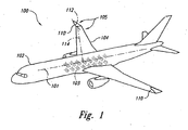
- Figure 1 is a top isometric view of an aircraft having a wing/winglet combination.
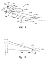
- Figure 2 is an enlarged exploded isometric view of the wing/winglet combination of Figure 1 .
- Figure 3 is an unfolded top plan view of the wing/winglet combination of Figure 2 illustrating relative sweep angles of the wing quarter-chord line and the winglet quarter-chord line.
- Figure 4 is an enlarged rear elevation view of the winglet of Figure 2 configured.
- Figure 5A is a side elevation view of a partial-chord winglet configured in accordance with an embodiment of the invention.
- Figure 5B is a side elevation view of a partial-chord winglet not falling within the scope of the claims.
- Figure 6 illustrates a graph showing a reduction in induced drag that can be achieved with a forward-swept winglet.
- Figure 7 illustrates a table comparing a drag reduction of an aft-swept winglet to a drag reduction of a forward-swept winglet.
- tip devices for use with airfoils such as aircraft wings, and methods for incorporating such tip devices into existing wing designs. Certain specific details are set forth in the following description and in Figures 1-7 . Other details describing well-known structures and systems often associated with aircraft and aircraft wings are not set forth in the following description to avoid unnecessarily obscuring the description of the various embodiments of the invention.
- Figure 1 is a top isometric view of an aircraft 100 having a wing/winglet combination 105.
- the aircraft 100 includes an airfoil such as a wing 104 extending outwardly from a fuselage 102.
- the fuselage 102 can be aligned along a longitudinal axis 101 and can include a passenger compartment 103 configured to carry a plurality of passengers (not shown).
- the passenger compartment 103 can be configured to carry at least 50 passengers.
- the passenger compartment 103 can be configured to carry at least 150 passengers.
- the passenger compartment 103 can be configured to carry other numbers of passengers.
- the passenger compartment 103 can be omitted.
- the wing 104 can be an existing wing configuration to which forward-swept winglets 110 have been added to form the wing/winglet combination 105.
- the phrase "existing wing configuration" in this context means an existing or "baseline" wing configuration that was originally designed to operate without wing tip devices.
- the forward-swept winglets 110 (“winglets 110") can be retrofitted to an existing wing to reduce the induced drag and increase fuel efficiency.
- the winglets 110 can be incorporated into the design of a new derivative aircraft that utilizes an existing wing configuration.
- the winglet 110 of the illustrated embodiment is combined with a wing
- the winglet 110 can be combined with other types of airfoils to reduce aerodynamic drag and/or serve other purposes.
- the winglet 110 can be combined with an aft-mounted horizontal stabilizer.
- the winglet 110 can be combined with a forward-wing or canard to reduce the aerodynamic drag on the canard.
- the winglet 110 can be combined with other airfoils.
- the term winglets shall refer to any wingtip device configured in accordance with this disclosure.
- the wing 104 defines a wing quarter-chord line 114 that is swept at least generally aft relative to the longitudinal axis 101
- the winglet 110 defines a winglet quarter-chord line 112 that is swept at least generally forward relative to the wing quarter-chord line 114.
- sweeping the winglet quarter-chord line 112 forward in this manner can favorably change the spanload on the combination of the wing 104 and the winglet 110 to provide an increased drag reduction over a conventional aft-swept winglet.
- FIG 2 is an enlarged exploded isometric view of the wing/winglet combination 105 of Figure 1 .
- the wing 104 includes a wing tip portion 238 and a wing root portion 236.
- the wing root portion 236 can be configured to be fixedly attached to the fuselage 102 ( Figure 1 ) and can define a wing root chord 256.
- the wing tip portion 238 can similarly define a wing tip chord 258 offset from the wing root chord 256 along the wing quarter-chord line 114.
- the wing tip chord 258 has a wash-out twist relative to the wing root chord 256, as illustrated by the twist angle 259.
- Conventional aircraft wings lacking wing tip devices typically employ such wash-out twist to reduce the lift distribution toward the wing tip and in turn reduce the bending load at the wing root. Reducing the bending load at the wing root can favorably reduce the structural weight of the wing, albeit at the expense of a slight drag increase.
- the winglet 110 includes a winglet tip portion 218 and a winglet root portion 216.
- the winglet root portion 216 can be configured to be fixedly attached to the wing tip portion 238 of the wing 104 and can define a winglet root chord 226.
- the winglet tip portion 218 can similarly define a winglet tip chord 228 offset from the winglet root chord 226 along the winglet quarter-chord line 112.
- the winglet quarter-chord line 112 is swept at least generally forward relative to the wing quarter-chord line 114 to favorably change the spanload on the wing 104 and in turn reduce the induced drag on the wing 104.
- the wing 104 includes a wing leading edge portion 262 and a wing trailing edge portion 263.
- the winglet 110 can include a winglet leading edge portion 242 and a winglet trailing edge portion 243.
- the winglet 110 can be a full-chord winglet with the winglet leading edge portion 242 positioned at least proximate to the wing leading edge portion 262, and the winglet trailing edge portion 243 positioned at least proximate to the wing trailing edge portion 263, as shown in figure 1 , 2 and 3 .
- partial-chord winglets can be fixedly attached to the wing 104 such that the winglet leading edge portion 242 and/or the winglet trailing edge portion 243 - is not proximate to the wing trailing edge portion 263.
- the wing 104 can have a general trapezoidal planform with an aspect ratio of about 10 and a taper ratio of about 0.25. In other embodiments, the wing 104 can have other aspect ratios and other taper ratios. For example, in one other embodiment, the wing 104 can have an aspect ratio greater than 10 and/or a taper ratio greater than 0.25. In another embodiment, the wing 104 can have an aspect ratio less than 10 and/or a taper ratio less than 0.25. In a further aspect of this embodiment, the wing quarter-chord line 114 can be swept aft at an angle 291 of about 35 degrees with respect to the longitudinal axis 101.
- the wing quarter-chord line 114 can be positioned at other angles relative to the longitudinal axis 101.
- the wing 104 can be at least generally unswept.
- the wing 104 can be swept forward.
- the winglet 110 can have a length of about 15% of the semi-span of the wing 104 and a taper ratio of about 0.50.
- the winglet quarter-chord line 112 can be swept forward at an angle 292 of about 35 degrees with respect to the wing tip chord 258.
- the winglet 110 can have other lengths, other taper ratios, and other sweep angles.
- the winglet 110 can have a length of about 10% of the semi-span of the wing 104, a taper ratio of about 0.40, and a forward sweep angle of about 25 degrees with respect to the wing tip chord 258.
- Figure 3 is an unfolded top plan view of the wing/winglet combination 105 of Figure 2 illustrating the relative sweep angles of the wing quarter-chord line 114 and the winglet quarter-chord line 112.
- the winglet 110 is folded outward and downward in Figure 3 about the wing tip chord 258 so that it lies in the same plane as the wing 104.
- This unfolded configuration illustrates that the winglet quarter-chord line 112 is swept forward with respect to the wing quarter-chord line 114, as shown by the forward sweep angle 359.
- forward swept winglet shall refer to a winglet having a quarter-chord line that is swept forward relative to the wing quarter-chord line when the winglet is brought into plane with the wing as shown in Figure 3 .
- the quarter-chord line of the winglet 112 may be swept aft relative to the longitudinal axis 101, but the winglet 110 may still be a "forward swept winglet” because the winglet quarter-chord line 112 is swept forward relative to the wing quarter-chord line 114.
- Figure 4 is an enlarged rear elevation view of the winglet 110 of Figure 2 .
- the winglet 110 extends at least generally upward with respect to the wing 104 such that the winglet 110 is at least generally perpendicular to the wing 104.
- the winglet 110 can extend at other angles with respect to the wing 104.
- the winglet 110 can extend at least generally outward from the wing 104 in a horizontal direction and, as illustrated by a second phantom position 472, the winglet 110 can extend at least generally upward and inward with respect to the wing 104 and, as illustrated by a third phantom position 473, the winglet 110 can extend at least generally downward and inward with respect to the wing 104 and the winglet 110 can assume a range of different cant angles between the second position 472 and the third position 473.
- Such cant angles can depend on a number of factors, including, for example, mitigating transonic shock interaction, reducing structural loads, and/or optimizing the reduction of aerodynamic drag.
- winglets in accordance with the present disclosure can be combined with a range of wing configurations to provide reductions in induced drag.
- such winglets can be combined with wings having little or no dihedral.
- such winglets can be combined with wings having some dihedral.
- such winglets can be combined with wings having some anhedral.
- Figures 5A and 5B are side elevation views of partial-chord winglets 510a and 510b, respectively.
- Figure 5A illustrates an embodiment of the invention falling within the scope of the claims.
- the partial-chord winglet 510a includes a winglet root chord 526a that is shorter than the adjacent wing tip chord 258.
- the partial-chord winglet 510a includes a winglet leading edge portion 542a and a winglet trailing edge portion 543a.
- the winglet leading edge portion 542a can be positioned at least proximate to the wing leading edge portion 262, and the winglet trailing edge portion 543a can be offset from the wing trailing edge portion 263 toward the wing leading edge portion 262.
- the partial-chord winglet 510a is swept forward.
- partial-chord winglets configured can be swept aft.
- the partial-chord winglet 510b includes a quarter-chord line 512 that is swept at least generally aft. It is expected that the forward position of the partial-chord winglet 510b can provide additional drag reduction benefits over a similarly configured aft-swept winglet positioned more toward the trailing edge portion 263 of the wing 104.
- Figure 6 illustrates a graph 600 showing a reduction in induced drag that can be achieved by a forward-swept winglet configured.
- Spanloads 1-5 for various wing and wing/winglet configurations, as measured along a vertical axis 692, are plotted against a nondimensional spanwise coordinate eta, as measured along a horizontal axis 694.
- An eta value of 1.00 corresponds to the tip of the wing 104 ( Figures 1-3 )
- an eta of 1.15 corresponds to the tip of the winglet 110 (also shown in Figures 1-3 ).
- the data presented in Figure 6 is theoretical and based on calculations. Accordingly, Figure 6 illustrates an expected reduction in induced drag, as opposed to a measured reduction.
- Spanload 1 is a theoretical ideal spanload (i.e., an elliptical spanload) for a flat wing having the same span as the wing 104.
- Spanload 2 is a compromised (i.e., triangular) spanload for the wing 104 with conventional wing tip wash-out.
- Spanload 3 is a theoretical ideal spanload for a wing with a vertical winglet. The wing/winglet combination associated with spanload 3 has accordingly been optimized to provide the optimum spanload shown.
- This optimization necessarily includes changing the wash-out of the wing 104 because, as noted above, this wash-out twist would otherwise produce a spanload with much less load on the outboard portion of the wing (e.g., the eta range between 0.5 and 1.0), similar to spanload 4.
- Spanload 4 is a theoretical best available spanload that can be achieved by attaching a 35 degree aft-swept winglet to the wing 104 without changing the twist of the wing 104.
- the twist of the winglet is optimized to produce the lowest possible induced drag consistent with the twist of the existing wing.
- spanload 5 is a theoretical best available spanload that can be achieved by attaching a 35 degree forward-swept winglet to the wing 104 without changing the twist of the wing 104. Comparing spanload 4 to spanload 5 shows that a forward-swept winglet can increase the spanload on both the tip portion of the baseline wing and the winglet, as compared to a comparable aft-swept winglet.
- One advantage of this feature is that increasing the spanload in this manner can provide a corresponding reduction in induced drag.
- Figure 7 illustrates a table 700 comparing the drag reduction of spanload 4 (aft-swept winglet) to the drag reduction of spanload 5 (forward-swept winglet).
- Spanload identifiers are shown in column 702
- winglet sweep is shown in column 704
- induced drag increments relative to the baseline wing 104 without any winglet and as percentages of the ideal induced drag of the baseline wing 104 without any winglets are shown in column 706.
- the aft-swept winglet is seen to provide an induced drag reduction equivalent to 6.3% of the ideal induced drag (spanload 1) as compared to the baseline wing 104 without a winglet (spanload 2).
- the forward-swept winglet is seen to provide an induced drag reduction equivalent to 7.9% of the ideal induced drag as compared to the baseline wing 104 without a winglet. Accordingly, in the illustrated embodiment, the data in table 700 suggests that a forward-swept winglet can provide about a 25% improvement in drag reduction over a comparable aft-swept winglet.
Landscapes
- Engineering & Computer Science (AREA)
- Aviation & Aerospace Engineering (AREA)
- Mechanical Engineering (AREA)
- Structures Of Non-Positive Displacement Pumps (AREA)
Claims (12)
- Tragflächen-/Wingletkombination, umfassend:eine Tragfläche mit einem Tragflächenwurzelteil und einem Tragflächenspitzenteil, der eine Tragflächenspitzensehne (258) definiert, wobei das Tragflächenspitzenteil zum Tragflächenwurzelteil beabstandet ist, wobei das Tragflächenspitzenteil eine Schränkung in Bezug auf das Tragflächenwurzelteil aufweist; undein einzelnes Winglet (510a), das sich von dem Tragflächenspitzenteil der Tragfläche auswärts erstreckt, wobei eine 1/4-Punktlinie (112) des Winglet so eingerichtet ist, dass sie im Verhältnis zu einer 1/4-Punktlinie (114) der Tragfläche, mit der das Winglet (510a) verbunden ist, vorgepfeilt ist, wobei das Winglet direkt an dem Tragflächenspitzenteil starr befestigt ist, wobei die Tragfläche ein Tragflächenanströmkantenteil (262) und ein Tragflächenabströmkantenteil (263) aufweist, und das Winglet (510a) einen Wingletanströmkantenteil (542a) und ein Wingletabströmkantenteil (543a) aufweist, wobei alle Anströmkantenteile des Winglet (542a) vorderhalb der Tragflächenspitzensehne (258) angeordnet sind, und wobei sich die Tragfläche in eine erste Richtung erstreckt und das Winglet (510a) sich in eine zweite Richtung erstreckt, wobei die zweite Richtung im Wesentlichen rechtwinklig zur ersten Richtung ist, wobei das Winglet (510a) ferner einen Wingletwurzelteil (216) umfasst, der eine Wingletwurzelsehne (226) definiert,wobei die Wingletwurzelsehne (226) an die Tragflächenspitzensehne (258) angrenzt,wobei das Wingletanströmkantenteil (542a) nahe zum Tragflächenanströmkantenteil (262) angeordnet und wobei die Wingletwurzelsehne (226) kürzer als die angrenzende Tragflächenspitzensehne (258) ist, und der Wingletabströmkantenteil (543a) zum Tragflächenabströmkantenteil (263) in Richtung des Tragflächenanströmkantenteils (262) versetzt ist.
- Tragflächen-/Wingletkombination nach Anspruch 1, wobei die Tragflächenspitzensehne ungefähr doppelt so lang ist wie die Wingletwurzelsehne (226).
- Tragflächen-/Wingletkombination nach Anspruch 1 oder 2, wobei die zweite Richtung im Wesentlichen rechtwinklig und aufwärts im Verhältnis zur ersten Richtung verläuft.
- Tragflächen-/Wingletkombination nach einem der Ansprüche 1 - 3, wobei die Tragfläche einen Flugzeugtragflügel (104) umfasst, und wobei der Flugzeugtragflügel (104) ein Flügelwurzelteil (236) aufweist, das dafür konfiguriert ist, an einem Flugzeugrumpf (102) befestigt zu werden, und ein von dem Flügelwurzelteil (236) beabstandetes Flügelspitzenteil (238), wobei das Flügelspitzenteil (238) eine Schränkung in Bezug auf das Flügelwurzelteil (236) aufweist.
- Tragflächen-/Wingletkombination nach einem der Ansprüche 1 - 4, wobei die Tragfläche einen Entenflügel umfasst und der Entenflügel ein Entenflügelwurzelteil aufweist, das dafür konfiguriert ist, an einem Flugzeugrumpf (102) befestigt zu werden, und ein von dem Entenflügelwurzelteil beabstandetes Entenflügelspitzenteil, wobei das Entenflügelspitzenteil eine Schränkung in Bezug auf das Entenflügelwurzelteil aufweist.
- Flugzeugsystem (100) mit der Tragflächen-/ Wingletkombination nach einem der Ansprüche 1 - 5, wobei die Tragfläche umfasst:einen Flügel (104) mit einem Flügelspitzenteil (238) und einen Flügelwurzelteil (236), wobei das Flügelwurzelteil (236) eine Flügelwurzelsehne (256) definiert und das Flügelspitzenteil (238) eine Flügelspitzensehne (258) definiert, und wobei die Flügelspitzensehne (258) eine Schränkung in Bezug auf die Flügelwurzelsehne (256) aufweist und gegenüber der Flügelwurzelsehne (256) entlang einer 1/4-Punktlinie (114) des Flügels versetzt ist; undein Winglet (110) mit einem Wingletspitzenteil (218) und einem Wingletwurzelteil (216), wobei das Wingletwurzelteil (216) eine Wingletwurzelsehne (226) definiert und direkt am Flügelspitzenteil (238) des Flügels (104) starr befestigt ist, bei Abwesenheit eines zweiten, sich von dem Flügelspitzenteil (238) auswärts erstreckenden Winglets, wobei das Wingletspitzenteil (218) eine Wingletspitzensehne (228) definiert und gegenüber der Wingletwurzelsehne (226) entlang einer 1/4-Punktlinie des Winglet (112) versetzt ist und die 1/4-Punktlinie (112) des Winglet zumindest im Grundsatz in Bezug auf die 1/4-Punktlinie (114) des Flügels vorgepfeilt ist,wobei die Wingletwurzelsehne (226) an die Flügelspitzensehne (258) angrenzt,wobei der Flügel (104) ein Flügelanströmkantenteil (262) und ein Flügelabströmkantenteil (263) aufweist und das Winglet (110) ein Wingletanströmkantenteil (542a) und ein Wingletabströmkantenteil (543a) aufweist, wobei das Wingletanströmkantenteil (542a) nahe dem Flügelanströmkantenteil (262) angeordnet ist, die Wingletwurzelsehne kürzer als die angrenzende Wingletspitzensehne (258) ist und das Wingletabströmkantenteil (543a) zum Flügelabströmkantenteil (263) in Richtung des Flügelanströmkantenteils (262) versetzt ist, wobei sich der Flügel (104) in eine erste Richtung erstreckt und das Winglet (110) sich in eine zweite Richtung erstreckt,wobei die zweite Richtung im Wesentlichen senkrecht zur ersten Richtung verläuft.
- Flugzeugsystem nach Anspruch 6, wobei die 1/4-Punktlinie (112) des Winglet vorgepfeilt ist, um einen Winkel (292) von circa 55 Grad zur Flügelspitzensehne (258) zu bilden.
- Flugzeugsystem nach Anspruch 6 oder 7, ferner einen Flugzeugrumpf (102) umfassend, wobei der Flügel (104) sich vom Flugzeugrumpf (102) auswärts erstreckt.
- Flugzeugsystem nach Anspruch 8, wobei der Flugzeugrumpf (102) entlang einer Längsachse (101) ausgerichtet ist, wobei die 1/4-Punktlinie (114) des Flügels zumindest im Grundsatz in Bezug auf die Längsachse (101) rückgepfeilt ist, und wobei die 1/4-Punktlinie (112) des Winglet zumindest im Grundsatz in Bezug auf die Längsachse (101) vorgepfeilt ist.
- Flugzeugsystem nach Anspruch 8 oder 9, wobei der Flugzeugrumpf (102) über eine Passagierkabine (103) verfügt, die zur Beförderung von mindestens 50 Passagieren ausgebildet ist.
- Verfahren zur Herstellung einer Tragflügel-/ Wingletkombination (105), wobei das Verfahren umfasst:das Zur-Verfügung-Stellen eines Flügels (104) mit einem Flügelwurzelteil (236) und einem Flügelspitzenteil (238), wobei das Flügelwurzelteil (236) dafür konfiguriert ist, am Rumpf (102) eines Flugzeugs (100) angebracht zu werden und eine Flügelwurzelsehne (256) zu definieren, wobei das Flügelspitzenteil (238) eine Flügelspitzensehne (258) definiert und gegenüber der Flügelwurzelsehne (256) entlang einer 1/4-Punktlinie (114) des Flügels versetzt ist, und wobei die Flügelspitzensehne (258) eine Schränkung in Bezug auf die Flügelwurzelsehne (256) aufweist;das Zur-Verfügung-Stellen eines Winglets (110) mit einem Wingletwurzelteil (216) und einem Wingletspitzenteil (218), wobei das Wingletwurzelteil (216) eine Wingletwurzelsehne (226) definiert, das Wingletspitzenteil (218) eine Wingletspitzensehne (228) definiert, und die Wingletspitzensehne (228) gegenüber der Wingletwurzelsehne (226) entlang einer 1 /4-Punktlinie (112) des Winglet versetzt ist; unddas starre Anbringen des Wingletwurzelteils (216) direkt am Flügelspitzenteil (238), bei Abwesenheit eines zweiten Winglets, das sich von dem Flügelspitzenteil (238) auswärts erstreckt, und zwar derart, dass die 1/4-Punktlinie (112) des Winglet zumindest im Grundsatz in Bezug auf die 1/4-Punktlinie (114) des Flügels vorgepfeilt ist,wobei die Wingletwurzelsehne (226) an die Flügelspitzensehne (258) angrenzt,wobei der Flügel (104) ein Flügelanströmkantenteil (262) und ein Flügelabströmkantenteil (263) aufweist und das Winglet (110) ein Wingletanströmkantenteil (542a) und ein Wingletabströmkantenteil (543a) aufweist,wobei das Wingletanströmkantenteil (542a) nahe dem Flügelanströmkantenteil (262) angeordnet ist, wobei alle Anströmkantenteile des Winglet (542a) vorderhalb der Flügelspitzensehne (258) angeordnet sind, undder Flügel (104) sich in eine erste Richtung erstreckt und das Winglet (110) sich in eine zweite Richtung erstreckt, wobei die zweite Richtung im Wesentlichen rechtwinklig zur ersten Richtung ist,wobei die Wingletwurzelsehne (226) kürzer als die angrenzende Flügelspitzensehne (258) ist und das Wingletabströmkantenteil (543a) zum Flügelabströmkantenteil (263) in Richtung des Flügelanströmkantenteils (262) versetzt ist.
- Verfahren zur Verbesserung der Luftwiderstandseigenschaften eines Flügels (104) mit einem Flügelwurzelteil (236) und einem Flügelspitzenteil (238), wobei das Flügelspitzenteil (238) eine Schränkung in Bezug auf das Flügelwurzelteil (236) aufweist, das Flügelwurzelteil (236) eine Flügelwurzelsehne (256) definiert und dafür konfiguriert ist, an einem Rumpf (102) eines Flugzeugs (100) befestigt zu werden, wobei das Flügelspitzenteil (238) eine Flügelspitzensehne (258) definiert, die gegenüber der Flügelwurzelsehne (256) entlang einer 1/4-Punktlinie (114) des Flügels versetzt ist, wobei das Verfahren umfasst:Veränderung der Tragflächenform (planform) des Flügels (104) durch:Zur-Verfügung-Stellen eines Winglets (110) mit einem Wingletwurzelteil (216) und einem Wingletspitzenteil (218), wobei das Wingletwurzelteil (216) eine Wingletwurzelsehne (226) definiert, das Wingletspitzenteil (218) eine Wingletspitzensehne (228) definiert, und die Wingletspitzensehne (228) gegenüber der Wingletwurzelsehne (226) entlang einer 1/4-Punktlinie (112) des Winglet versetzt ist; unddie starre Befestigung des Winglets (110) am Flügel (104) durch Befestigen des Wingletwurzelteils (216) direkt am Flügelspitzenteil (238) bei Abwesenheit eines zweiten, sich von dem Flügelspitzenteil (238) auswärts erstreckenden Winglets, wobei, wenn das Winglet (110) starr am Flügel (104) befestigt ist, die 1/4-Punktlinie (112) des Winglet zumindest im Grundsatz in Bezug auf die 1/4-Punktlinie (114) des Flügels vorgepfeilt ist, und wobei der Flügel (104) ein Flügelanströmkantenteil (262) und ein Flügelabströmkantenteil (263) aufweist und das Winglet (110) ein Wingletanströmkantenteil (542a) und ein Wingletabströmkantenteil (543a) aufweist,wobei das Wingletanströmkantenteil (542a) nahe dem Flügelanströmkantenteil (262) angeordnet ist, wobei alle Anströmkantenteile des Winglet (542a) vorderhalb der Flügelspitzensehne (258) angeordnet sind, undwobei sich der Flügel in eine erste Richtung erstreckt und das Winglet (110) sich in eine zweite Richtung erstreckt, und wobei die zweite Richtung im Wesentlichen rechtwinklig zur ersten Richtung verläuft,wobei die Wingletwurzelsehne (226) kürzer als die angrenzende Flügelspitzensehne (258) ist und das Wingletabströmkantenteil (543a) zum Flügelabströmkantenteil (263) in Richtung des Flügelanströmkantenteils (262) versetztet ist.
Priority Applications (1)
| Application Number | Priority Date | Filing Date | Title |
|---|---|---|---|
| DE602004010867T DE602004010867T3 (de) | 2003-06-30 | 2004-06-29 | Wirksame Flügelspitzenvorrichtung und Verfahren zum Einbau solcher Vorrichtungen in existierende Tragflächen |
Applications Claiming Priority (2)
| Application Number | Priority Date | Filing Date | Title |
|---|---|---|---|
| US611212 | 2003-06-30 | ||
| US10/611,212 US6886778B2 (en) | 2003-06-30 | 2003-06-30 | Efficient wing tip devices and methods for incorporating such devices into existing wing designs |
Publications (3)
| Publication Number | Publication Date |
|---|---|
| EP1493660A1 EP1493660A1 (de) | 2005-01-05 |
| EP1493660B1 EP1493660B1 (de) | 2007-12-26 |
| EP1493660B2 true EP1493660B2 (de) | 2012-10-24 |
Family
ID=33435430
Family Applications (1)
| Application Number | Title | Priority Date | Filing Date |
|---|---|---|---|
| EP04076872A Expired - Lifetime EP1493660B2 (de) | 2003-06-30 | 2004-06-29 | Wirksame Flügelspitzenvorrichtung und Verfahren zum Einbau solcher Vorrichtungen in existierende Tragflächen |
Country Status (3)
| Country | Link |
|---|---|
| US (1) | US6886778B2 (de) |
| EP (1) | EP1493660B2 (de) |
| DE (1) | DE602004010867T3 (de) |
Families Citing this family (49)
| Publication number | Priority date | Publication date | Assignee | Title |
|---|---|---|---|---|
| GB0326228D0 (en) * | 2003-11-10 | 2003-12-17 | Airbus Uk Ltd | Wing tip device |
| CA2554984A1 (en) * | 2004-01-30 | 2005-08-11 | Piet Ellnor | Wing-in-ground-effect craft |
| US8544800B2 (en) * | 2005-07-21 | 2013-10-01 | The Boeing Company | Integrated wingtip extensions for jet transport aircraft and other types of aircraft |
| GB0518755D0 (en) * | 2005-09-14 | 2005-10-19 | Airbus Uk Ltd | Wing tip device |
| FR2894558A1 (fr) * | 2005-12-12 | 2007-06-15 | Dassault Avions | Aile a ailette d'extremite de voilure et aeronef comportant une telle aile |
| US7644892B1 (en) | 2006-07-06 | 2010-01-12 | Alford Jr Lionel D | Blended winglet |
| DE102006055090A1 (de) * | 2006-11-21 | 2008-05-29 | Airbus Deutschland Gmbh | Flügelendform für einen Flügel, insbesondere von Luftfahrzeugen |
| US7744038B2 (en) * | 2007-06-15 | 2010-06-29 | The Boeing Company | Controllable winglets |
| US7900876B2 (en) * | 2007-08-09 | 2011-03-08 | The Boeing Company | Wingtip feathers, including forward swept feathers, and associated aircraft systems and methods |
| US20090084904A1 (en) * | 2007-10-02 | 2009-04-02 | The Boeing Company | Wingtip Feathers, Including Paired, Fixed Feathers, and Associated Systems and Methods |
| US8128035B2 (en) * | 2008-04-15 | 2012-03-06 | The Boeing Company | Winglets with recessed surfaces, and associated systems and methods |
| US9302766B2 (en) | 2008-06-20 | 2016-04-05 | Aviation Partners, Inc. | Split blended winglet |
| ES2561982T3 (es) | 2008-06-20 | 2016-03-01 | Aviation Partners, Inc. | Punta de ala curvada |
| CA2761317A1 (en) * | 2009-05-05 | 2010-11-11 | Aerostar Aircraft Corporation | Aircraft winglet design having a compound curve profile |
| WO2011070532A1 (en) * | 2009-12-10 | 2011-06-16 | University Of The Witwatersrand, Johannesburg | Aircraft wingtip arrangement |
| WO2011127938A1 (en) * | 2010-04-12 | 2011-10-20 | Airbus Operations Gmbh | Fixed wing of an aircraft |
| EP2383465A1 (de) * | 2010-04-27 | 2011-11-02 | Lm Glasfiber A/S | Windturbinenschaufel mit einer Lamellenanordnung |
| GB201011843D0 (en) * | 2010-07-14 | 2010-09-01 | Airbus Operations Ltd | Wing tip device |
| DE102010048139A1 (de) * | 2010-10-11 | 2012-04-12 | Eads Deutschland Gmbh | Fluggerät mit variabler Geometrie |
| US8439313B2 (en) * | 2010-10-15 | 2013-05-14 | The Boeing Company | Forward swept winglet |
| US8857761B2 (en) | 2010-10-27 | 2014-10-14 | Ata Engineering, Inc. | Variable geometry aircraft pylon structure and related operation techniques |
| GB201018185D0 (en) | 2010-10-28 | 2010-12-08 | Airbus Operations Ltd | Wing tip device attachment apparatus and method |
| DE102012103704B4 (de) | 2011-04-30 | 2025-11-06 | General Electric Renovables España, S.L. | Winglet für einen Rotorflügel einer Windkraftanlage |
| CA2838848C (en) | 2011-06-09 | 2020-09-29 | Aviation Partners, Inc. | The split spiroid |
| GB201115026D0 (en) * | 2011-08-31 | 2011-10-12 | Airbus Operations Ltd | Aircraft lighting device |
| US9567867B2 (en) | 2011-09-14 | 2017-02-14 | Ata Engineering, Inc. | Methods and apparatus for deployable swirl vanes |
| US20140197280A1 (en) * | 2011-11-22 | 2014-07-17 | Donald Earl Smith | Delta Wing Unmanned Aerial Vehicle (UAV) and Method of Manufacture of the Same |
| US9103325B2 (en) | 2012-03-20 | 2015-08-11 | General Electric Company | Winglet for a wind turbine rotor blade |
| US8936219B2 (en) | 2012-03-30 | 2015-01-20 | The Boeing Company | Performance-enhancing winglet system and method |
| US10562613B2 (en) * | 2013-12-04 | 2020-02-18 | Tamarack Aerospace Group, Inc. | Adjustable lift modification wingtip |
| EP3077281A4 (de) | 2013-12-05 | 2017-07-26 | Tamarack Aerospace Group, Inc. | Flügelspitzenvorrichtung |
| GB2524824B (en) * | 2014-04-04 | 2020-06-24 | Airbus Operations Ltd | An aircraft wing with a wing tip device and a strut |
| US9511850B2 (en) | 2014-04-12 | 2016-12-06 | The Boeing Company | Wing tip device for an aircraft wing |
| US9868517B2 (en) | 2014-08-13 | 2018-01-16 | The Boeing Company | Rotatable wing tip joint and method of making same |
| CN104875873B (zh) * | 2015-05-06 | 2017-03-01 | 万绍明 | 一种具有气动布局的飞机机翼和使用该机翼的飞机 |
| FR3037560B1 (fr) * | 2015-06-16 | 2018-06-01 | Airbus Operations | Aile d'aeronef comprenant un embout d'aile pilotable en incidence |
| EP3269635A1 (de) * | 2016-07-12 | 2018-01-17 | The Aircraft Performance Company UG | Flugzeugflügel |
| GB2559968A (en) * | 2017-02-22 | 2018-08-29 | Airbus Operations Ltd | A winglet and method of designing a winglet |
| EP3511243B1 (de) * | 2018-01-15 | 2021-12-29 | The Aircraft Performance Company GmbH | Flugzeugflügel |
| GB201805279D0 (en) * | 2018-03-29 | 2018-05-16 | Archangel Lightworks Ltd | Wing tips and wing tips construction design methods |
| US11319054B2 (en) * | 2018-05-31 | 2022-05-03 | Airbus Operations Gmbh | Wing arrangement for an aircraft |
| US11370526B2 (en) * | 2018-05-31 | 2022-06-28 | Airbus Operations Gmbh | Latching device for a wing arrangement for an aircraft |
| US11214353B2 (en) * | 2018-06-01 | 2022-01-04 | Airbus Operations Gmbh | Wing arrangement for an aircraft and aircraft |
| EP3587252A1 (de) * | 2018-06-28 | 2020-01-01 | Airbus Operations GmbH | Arretiersystem zum arretieren einer ersten flugzeugkomponente in bezug auf eine zweite flugzeugkomponente |
| CN111017191A (zh) * | 2019-12-19 | 2020-04-17 | 中国航空工业集团公司西安飞机设计研究所 | 一种翼梢小翼 |
| GB2615311A (en) * | 2022-01-31 | 2023-08-09 | Airbus Operations Ltd | Aircraft wing with movable wing tip device |
| GB2616252A (en) * | 2022-01-31 | 2023-09-06 | Airbus Operations Ltd | Aircraft with movable wing tip device |
| GB2628523B (en) * | 2022-11-16 | 2025-07-09 | Airbus Operations Ltd | Aircraft wing |
| US20240375770A1 (en) * | 2023-05-09 | 2024-11-14 | Textron Aviation Inc. | Scythe Wingtip Device |
Citations (1)
| Publication number | Priority date | Publication date | Assignee | Title |
|---|---|---|---|---|
| US4772499A (en) † | 1986-10-01 | 1988-09-20 | The Kendall Company | Novel tearable non-woven webs and products employing same |
Family Cites Families (14)
| Publication number | Priority date | Publication date | Assignee | Title |
|---|---|---|---|---|
| US4172574A (en) | 1976-06-16 | 1979-10-30 | National Research Development Corporation | Fluid stream deflecting members for aircraft bodies or the like |
| US4205810A (en) | 1977-12-19 | 1980-06-03 | The Boeing Company | Minimum drag wing configuration for aircraft operating at transonic speeds |
| EP0094064A1 (de) * | 1982-05-11 | 1983-11-16 | George Stanmore Rasmussen | An der Tragflügelspitze befestigte Vorrichtung zur Erhöhung des Vorschubs |
| US4455004A (en) * | 1982-09-07 | 1984-06-19 | Lockheed Corporation | Flight control device for airplanes |
| DE3242584A1 (de) * | 1982-11-18 | 1984-05-24 | Messerschmitt-Bölkow-Blohm GmbH, 8000 München | Anordnung von zusatzflaechen an den spitzen eines tragfluegels |
| US4671473A (en) * | 1984-11-08 | 1987-06-09 | Goodson Kenneth W | Airfoil |
| US5102068A (en) | 1991-02-25 | 1992-04-07 | Gratzer Louis B | Spiroid-tipped wing |
| US5275358A (en) | 1991-08-02 | 1994-01-04 | The Boeing Company | Wing/winglet configurations and methods for aircraft |
| US5348253A (en) | 1993-02-01 | 1994-09-20 | Gratzer Louis B | Blended winglet |
| US5634613A (en) | 1994-07-18 | 1997-06-03 | Mccarthy; Peter T. | Tip vortex generation technology for creating a lift enhancing and drag reducing upwash effect |
| FR2772715B1 (fr) * | 1997-12-22 | 2000-02-11 | Eurocopter France | Pale pour aeronef a voilure tournante |
| DE19926832B4 (de) * | 1999-06-12 | 2005-09-15 | Airbus Deutschland Gmbh | Unterschallflugzeug vorzugsweise mit gepfeilten Tragflügeln |
| US6484968B2 (en) | 2000-12-11 | 2002-11-26 | Fort F. Felker | Aircraft with elliptical winglets |
| US6547181B1 (en) | 2002-05-29 | 2003-04-15 | The Boeing Company | Ground effect wing having a variable sweep winglet |
-
2003
- 2003-06-30 US US10/611,212 patent/US6886778B2/en not_active Expired - Lifetime
-
2004
- 2004-06-29 DE DE602004010867T patent/DE602004010867T3/de not_active Expired - Lifetime
- 2004-06-29 EP EP04076872A patent/EP1493660B2/de not_active Expired - Lifetime
Patent Citations (1)
| Publication number | Priority date | Publication date | Assignee | Title |
|---|---|---|---|---|
| US4772499A (en) † | 1986-10-01 | 1988-09-20 | The Kendall Company | Novel tearable non-woven webs and products employing same |
Non-Patent Citations (2)
| Title |
|---|
| BOEING 747, FLIGHT INTERNATIONAL, 12 December 1968 (1968-12-12), pages 979 - 981 † |
| KC-135 WINGLET PROGRAM REVIEW-NASA CONFERENCE PUBLICATION 2211, 1 January 1982 (1982-01-01) † |
Also Published As
| Publication number | Publication date |
|---|---|
| US6886778B2 (en) | 2005-05-03 |
| EP1493660B1 (de) | 2007-12-26 |
| US20040262451A1 (en) | 2004-12-30 |
| DE602004010867T2 (de) | 2008-12-11 |
| DE602004010867T3 (de) | 2013-01-31 |
| EP1493660A1 (de) | 2005-01-05 |
| DE602004010867D1 (de) | 2008-02-07 |
Similar Documents
| Publication | Publication Date | Title |
|---|---|---|
| EP1493660B1 (de) | Wirksame Flügelspitzenvorrichtung und Verfahren zum Einbau solcher Vorrichtungen in existierende Tragflächen | |
| US9637226B2 (en) | Split winglet system | |
| US10005546B2 (en) | Split blended winglet | |
| EP2718182B1 (de) | Geteilter verbundstoffflügel | |
| EP1349778B1 (de) | Flugzeug mit elliptischen winglets | |
| US9056671B2 (en) | Fixed wing of an aircraft | |
| US20070262205A1 (en) | Retractable multiple winglet | |
| US11345461B2 (en) | Wing tip device |
Legal Events
| Date | Code | Title | Description |
|---|---|---|---|
| PUAI | Public reference made under article 153(3) epc to a published international application that has entered the european phase |
Free format text: ORIGINAL CODE: 0009012 |
|
| AK | Designated contracting states |
Kind code of ref document: A1 Designated state(s): AT BE BG CH CY CZ DE DK EE ES FI FR GB GR HU IE IT LI LU MC NL PL PT RO SE SI SK TR |
|
| AX | Request for extension of the european patent |
Extension state: AL HR LT LV MK |
|
| 17P | Request for examination filed |
Effective date: 20050126 |
|
| AKX | Designation fees paid |
Designated state(s): DE FR GB |
|
| 17Q | First examination report despatched |
Effective date: 20051013 |
|
| 17Q | First examination report despatched |
Effective date: 20051013 |
|
| GRAP | Despatch of communication of intention to grant a patent |
Free format text: ORIGINAL CODE: EPIDOSNIGR1 |
|
| GRAS | Grant fee paid |
Free format text: ORIGINAL CODE: EPIDOSNIGR3 |
|
| GRAA | (expected) grant |
Free format text: ORIGINAL CODE: 0009210 |
|
| AK | Designated contracting states |
Kind code of ref document: B1 Designated state(s): DE FR GB |
|
| REG | Reference to a national code |
Ref country code: GB Ref legal event code: FG4D |
|
| REF | Corresponds to: |
Ref document number: 602004010867 Country of ref document: DE Date of ref document: 20080207 Kind code of ref document: P |
|
| ET | Fr: translation filed | ||
| RAP2 | Party data changed (patent owner data changed or rights of a patent transferred) |
Owner name: THE BOEING COMPANY |
|
| PLBI | Opposition filed |
Free format text: ORIGINAL CODE: 0009260 |
|
| PLAX | Notice of opposition and request to file observation + time limit sent |
Free format text: ORIGINAL CODE: EPIDOSNOBS2 |
|
| PLAX | Notice of opposition and request to file observation + time limit sent |
Free format text: ORIGINAL CODE: EPIDOSNOBS2 |
|
| 26 | Opposition filed |
Opponent name: AIRBUS FRANCE SAS/AIRBUS UK LIMITED/ A Effective date: 20080924 |
|
| PLAF | Information modified related to communication of a notice of opposition and request to file observations + time limit |
Free format text: ORIGINAL CODE: EPIDOSCOBS2 |
|
| PLBB | Reply of patent proprietor to notice(s) of opposition received |
Free format text: ORIGINAL CODE: EPIDOSNOBS3 |
|
| PUAH | Patent maintained in amended form |
Free format text: ORIGINAL CODE: 0009272 |
|
| STAA | Information on the status of an ep patent application or granted ep patent |
Free format text: STATUS: PATENT MAINTAINED AS AMENDED |
|
| 27A | Patent maintained in amended form |
Effective date: 20121024 |
|
| AK | Designated contracting states |
Kind code of ref document: B2 Designated state(s): DE FR GB |
|
| REG | Reference to a national code |
Ref country code: DE Ref legal event code: R102 Ref document number: 602004010867 Country of ref document: DE Effective date: 20121024 |
|
| REG | Reference to a national code |
Ref country code: DE Ref legal event code: R082 Ref document number: 602004010867 Country of ref document: DE Representative=s name: BEETZ & PARTNER PATENT- UND RECHTSANWAELTE, DE |
|
| REG | Reference to a national code |
Ref country code: DE Ref legal event code: R081 Ref document number: 602004010867 Country of ref document: DE Owner name: THE BOEING COMPANY, US Free format text: FORMER OWNER: THE BOING CO., SEATTLE, US Effective date: 20130325 Ref country code: DE Ref legal event code: R082 Ref document number: 602004010867 Country of ref document: DE Representative=s name: BEETZ & PARTNER PATENT- UND RECHTSANWAELTE, DE Effective date: 20130325 Ref country code: DE Ref legal event code: R082 Ref document number: 602004010867 Country of ref document: DE Representative=s name: BEETZ & PARTNER MBB PATENT- UND RECHTSANWAELTE, DE Effective date: 20130325 Ref country code: DE Ref legal event code: R081 Ref document number: 602004010867 Country of ref document: DE Owner name: THE BOEING COMPANY, CHICAGO, US Free format text: FORMER OWNER: THE BOING CO., SEATTLE, WASH., US Effective date: 20130325 Ref country code: DE Ref legal event code: R082 Ref document number: 602004010867 Country of ref document: DE Representative=s name: BEETZ & PARTNER MBB, DE Effective date: 20130325 Ref country code: DE Ref legal event code: R082 Ref document number: 602004010867 Country of ref document: DE Representative=s name: BEETZ & PARTNER MBB PATENTANWAELTE, DE Effective date: 20130325 |
|
| REG | Reference to a national code |
Ref country code: FR Ref legal event code: PLFP Year of fee payment: 13 |
|
| REG | Reference to a national code |
Ref country code: FR Ref legal event code: PLFP Year of fee payment: 14 |
|
| REG | Reference to a national code |
Ref country code: FR Ref legal event code: PLFP Year of fee payment: 15 |
|
| P01 | Opt-out of the competence of the unified patent court (upc) registered |
Effective date: 20230503 |
|
| PGFP | Annual fee paid to national office [announced via postgrant information from national office to epo] |
Ref country code: FR Payment date: 20230626 Year of fee payment: 20 Ref country code: DE Payment date: 20230626 Year of fee payment: 20 |
|
| PGFP | Annual fee paid to national office [announced via postgrant information from national office to epo] |
Ref country code: GB Payment date: 20230627 Year of fee payment: 20 |
|
| REG | Reference to a national code |
Ref country code: DE Ref legal event code: R071 Ref document number: 602004010867 Country of ref document: DE |
|
| PG25 | Lapsed in a contracting state [announced via postgrant information from national office to epo] |
Ref country code: GB Free format text: LAPSE BECAUSE OF EXPIRATION OF PROTECTION Effective date: 20240628 |
|
| REG | Reference to a national code |
Ref country code: GB Ref legal event code: PE20 Expiry date: 20240628 |
|
| PG25 | Lapsed in a contracting state [announced via postgrant information from national office to epo] |
Ref country code: GB Free format text: LAPSE BECAUSE OF EXPIRATION OF PROTECTION Effective date: 20240628 |