EP1493690A2 - Ensemble d'entraínement par courroie pour dispositif d'inspection de récipients - Google Patents
Ensemble d'entraínement par courroie pour dispositif d'inspection de récipients Download PDFInfo
- Publication number
- EP1493690A2 EP1493690A2 EP04253464A EP04253464A EP1493690A2 EP 1493690 A2 EP1493690 A2 EP 1493690A2 EP 04253464 A EP04253464 A EP 04253464A EP 04253464 A EP04253464 A EP 04253464A EP 1493690 A2 EP1493690 A2 EP 1493690A2
- Authority
- EP
- European Patent Office
- Prior art keywords
- belt
- drive
- pair
- belt drive
- drives
- Prior art date
- Legal status (The legal status is an assumption and is not a legal conclusion. Google has not performed a legal analysis and makes no representation as to the accuracy of the status listed.)
- Granted
Links
Images




Classifications
-
- B—PERFORMING OPERATIONS; TRANSPORTING
- B65—CONVEYING; PACKING; STORING; HANDLING THIN OR FILAMENTARY MATERIAL
- B65G—TRANSPORT OR STORAGE DEVICES, e.g. CONVEYORS FOR LOADING OR TIPPING, SHOP CONVEYOR SYSTEMS OR PNEUMATIC TUBE CONVEYORS
- B65G29/00—Rotary conveyors, e.g. rotating discs, arms, star-wheels or cones
- B65G29/02—Rotary conveyors, e.g. rotating discs, arms, star-wheels or cones for inclined or vertical transit
-
- B—PERFORMING OPERATIONS; TRANSPORTING
- B65—CONVEYING; PACKING; STORING; HANDLING THIN OR FILAMENTARY MATERIAL
- B65G—TRANSPORT OR STORAGE DEVICES, e.g. CONVEYORS FOR LOADING OR TIPPING, SHOP CONVEYOR SYSTEMS OR PNEUMATIC TUBE CONVEYORS
- B65G15/00—Conveyors having endless load-conveying surfaces, i.e. belts and like continuous members, to which tractive effort is transmitted by means other than endless driving elements of similar configuration
- B65G15/10—Conveyors having endless load-conveying surfaces, i.e. belts and like continuous members, to which tractive effort is transmitted by means other than endless driving elements of similar configuration comprising two or more co-operating endless surfaces with parallel longitudinal axes, or a multiplicity of parallel elements, e.g. ropes defining an endless surface
- B65G15/12—Conveyors having endless load-conveying surfaces, i.e. belts and like continuous members, to which tractive effort is transmitted by means other than endless driving elements of similar configuration comprising two or more co-operating endless surfaces with parallel longitudinal axes, or a multiplicity of parallel elements, e.g. ropes defining an endless surface with two or more endless belts
- B65G15/14—Conveyors having endless load-conveying surfaces, i.e. belts and like continuous members, to which tractive effort is transmitted by means other than endless driving elements of similar configuration comprising two or more co-operating endless surfaces with parallel longitudinal axes, or a multiplicity of parallel elements, e.g. ropes defining an endless surface with two or more endless belts the load being conveyed between the belts
-
- B—PERFORMING OPERATIONS; TRANSPORTING
- B65—CONVEYING; PACKING; STORING; HANDLING THIN OR FILAMENTARY MATERIAL
- B65G—TRANSPORT OR STORAGE DEVICES, e.g. CONVEYORS FOR LOADING OR TIPPING, SHOP CONVEYOR SYSTEMS OR PNEUMATIC TUBE CONVEYORS
- B65G2201/00—Indexing codes relating to handling devices, e.g. conveyors, characterised by the type of product or load being conveyed or handled
- B65G2201/02—Articles
- B65G2201/0235—Containers
- B65G2201/0244—Bottles
-
- B—PERFORMING OPERATIONS; TRANSPORTING
- B65—CONVEYING; PACKING; STORING; HANDLING THIN OR FILAMENTARY MATERIAL
- B65G—TRANSPORT OR STORAGE DEVICES, e.g. CONVEYORS FOR LOADING OR TIPPING, SHOP CONVEYOR SYSTEMS OR PNEUMATIC TUBE CONVEYORS
- B65G2203/00—Indexing code relating to control or detection of the articles or the load carriers during conveying
- B65G2203/04—Detection means
- B65G2203/042—Sensors
- B65G2203/044—Optical
-
- G—PHYSICS
- G01—MEASURING; TESTING
- G01N—INVESTIGATING OR ANALYSING MATERIALS BY DETERMINING THEIR CHEMICAL OR PHYSICAL PROPERTIES
- G01N33/00—Investigating or analysing materials by specific methods not covered by groups G01N1/00 - G01N31/00
- G01N33/38—Concrete; Lime; Mortar; Gypsum; Bricks; Ceramics; Glass
- G01N33/386—Glass
Definitions
- the present invention relates to machines which inspect containers such as bottles for defects, and more particularly to such machines wherein a bottle is conveyed through one or more inspection stations via a belt conveyor having opposed pairs of belts.
- a belt drive conveyor system for a machine for inspecting containers as defined in claim 1.
- the invention also consists in a machine for inspecting containers incorporating a conveyor system as above defined.
- Figure 1 is a schematic showing of an inspection machine 10 which inspects a row of bottles 12 conveyed to the machine by an infeed conveyor 14. Any of a variety of inspections can be carried out by the machine.
- Figure 2 illustrates the belt conveyor mechanism 20 for this machine which receives, i.e. picks up, bottles from the infeed conveyor 14, conveys them through one or more inspection locations, and releases them to a discharge conveyor 16.
- the infeed and discharge conveyors have front guards 17 which, together with a front guard 18 for the inspection equipment (light sources, cameras, etc.), define the front face of the infeed/discharge conveyor system.
- the belt conveyor mechanism has an upper opposed pair of belt drives 22 and a lower opposed pair of belt drives 24.
- Each of the belt drives 22, 24 is cantilevered from a generally vertical or upwardly extending strut 26 which is integral with a horizontal slide member 28.
- the two slide members of the upper/lower opposed pair of belt drives each include a rack portion 29 (one shown in Figure 4) which is operatively associated with an idler pinion 30.
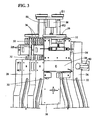
- the two slide members 28 of an opposed pair of belt drives are supported for lateral displacement by three pairs of rollers 32 ( Figures 3 and 4) which are mounted on a vertically displaceable carriage 34.
- the top slide member is supported between the top and middle roller pair and the bottom slide member (shown in Figure 3 but omitted from Figure 4 from below the lower rack portion 5 to reveal otherwise concealed components) is supported between the middle and bottom roller pairs.
- a slide member 28 can enter a suitable hole 31 in an associated opposed strut 26 when the opposed pair of belt drives is closed towards each other.
- the carriage 34 also supports upper and lower opposed pairs of rollers 36 which are captured by outer tracks (not shown) on a housing 38 ( Figure 4) which is secured to the machine frame to depend over the inspection area, thus mounting the carriage for vertical displacement relative to the housing 38.
- a pulley 42 drives a screw 44 which is threadedly received by a corresponding nut secured within the lower slide member (not shown in Figure 4) which displaces the lower slide member and the attached strut.
- This displacement will be mirrored by the associated upper slide member and its opposed belt drive, since the upper and lower rack portions of the slide members are coupled together via the idler pinion 30. Operation of an open/close motor will accordingly conjointly horizontally displace the associated opposed upper or lower belt drives either towards or away from each other.
- the displacement may be effected or supplemented by driving the associated pinions 30.
- the housing 38 is integral with a mounting 39 which is secured to the machine frame, and mounted on the housing are a pair of up/down motors 50.
- One motor is associated with the upper drive belts and the other is associated with the lower drive belts.
- Each motor 50 operates a pulley 51 which rotatably drives a screw 53 which is operatively received by an elongated nut 52 which is joined to the carriage 34 via a bracket 54.
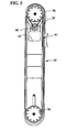
- Each belt drive (Fig. 5) has a casing or arm 55 which supports a pulley 56 at either end of the arm. These pulleys support a belt 57 which is driven via a timing belt 58 interconnecting one of these pulleys with a step motor drive 60.
- the other pulley 56 is an idler pulley.
- the step motor is mounted on top of the casing as shown in Fig. 2.
- the step motor for a lower belt drive is mounted on the top surface of the lower casing so that it can enter a pocket or cutout 62 defined in the upper casing. To facilitate vertical displacement, each assembly is counterbalanced to substantially remove the weight of the assembly.
- Figure 2 shows the upper and lower belt drive pairs being located in a large ware 12A configuration with the upper and lower belt drives being vertically stacked.
- Figure 6 illustrates the location of the upper and lower drive belt pairs in a small or mini ware 12B configuration.
- the upper belt drive pair is elevated to separate the vertically adjacent belt drives so that they can be displaced relatively horizontally (the top of the motor on the lower drive is clear of the upper casing).
- the lower belt drive pair is horizontally separated to the location where both lower belt drives are horizontally cleared of the front wall 17,18 and rear of the conveyor.
- the lower belt drives are then lowered until the top of the belt drive (its motor) is below the surface of the infeed/outfeed conveyors 14.
- the upper drive belt pair is now lowered to a location where the casing is just above the top surface of the conveyor 14. Now the drive belts of the upper drive belt pair can be located adjacent the sidewall of mini ware 12B.
Landscapes
- Engineering & Computer Science (AREA)
- Mechanical Engineering (AREA)
- Structure Of Belt Conveyors (AREA)
- Investigating Materials By The Use Of Optical Means Adapted For Particular Applications (AREA)
- Sorting Of Articles (AREA)
- Intermediate Stations On Conveyors (AREA)
Applications Claiming Priority (2)
| Application Number | Priority Date | Filing Date | Title |
|---|---|---|---|
| US10/610,233 US6793067B1 (en) | 2003-06-30 | 2003-06-30 | Container inspection machine |
| US610233 | 2003-06-30 |
Publications (3)
| Publication Number | Publication Date |
|---|---|
| EP1493690A2 true EP1493690A2 (fr) | 2005-01-05 |
| EP1493690A3 EP1493690A3 (fr) | 2005-12-21 |
| EP1493690B1 EP1493690B1 (fr) | 2006-10-18 |
Family
ID=32991136
Family Applications (1)
| Application Number | Title | Priority Date | Filing Date |
|---|---|---|---|
| EP04253464A Expired - Lifetime EP1493690B1 (fr) | 2003-06-30 | 2004-06-10 | Ensemble d'entraînement par courroie pour dispositif d'inspection de récipients |
Country Status (4)
| Country | Link |
|---|---|
| US (1) | US6793067B1 (fr) |
| EP (1) | EP1493690B1 (fr) |
| JP (1) | JP4592332B2 (fr) |
| DE (1) | DE602004002808T2 (fr) |
Cited By (2)
| Publication number | Priority date | Publication date | Assignee | Title |
|---|---|---|---|---|
| WO2008058658A3 (fr) * | 2006-11-15 | 2008-10-23 | Khs Ag | Procédé d'inspection ou de surveillance de bouteilles ou récipients analogues, et dispositif d'inspection de bouteilles ou récipients analogues |
| RU2426098C2 (ru) * | 2006-01-19 | 2011-08-10 | Кхс Аг | Способ и устройство для контроля бутылок или им подобных емкостей из просвечивающегося материала |
Families Citing this family (5)
| Publication number | Priority date | Publication date | Assignee | Title |
|---|---|---|---|---|
| US8274001B2 (en) * | 2009-12-31 | 2012-09-25 | Mettler-Toledo, LLC | Weighing apparatus having opposed wheels |
| NL2011447C2 (en) * | 2012-09-14 | 2014-06-19 | Nn Inc | Roller end face inspection device. |
| US9322787B1 (en) | 2014-10-18 | 2016-04-26 | Emhart Glass S.A. | Glass container inspection machine with a graphic user interface |
| US20170081129A1 (en) * | 2015-09-14 | 2017-03-23 | Industrial Dynamics Company Ltd | System and method for transporting containers in an inspection environment |
| USD918278S1 (en) * | 2019-08-28 | 2021-05-04 | Ckd Corporation | Printed circuit board inspection machine |
Family Cites Families (12)
| Publication number | Priority date | Publication date | Assignee | Title |
|---|---|---|---|---|
| US3901381A (en) * | 1973-10-10 | 1975-08-26 | Ball Brothers Service Corp | Automatic ware handler |
| JPH04350015A (ja) * | 1991-05-27 | 1992-12-04 | Enutetsuku:Kk | 物体の回転搬送装置 |
| US5422476A (en) * | 1993-09-15 | 1995-06-06 | Emhart Glass Machinery Investments Inc. | Glass container inspection machine |
| JPH07117837A (ja) * | 1993-10-21 | 1995-05-09 | Eishin Seisakusho:Kk | 転倒し易い容器等の中間抱き込み搬送機 |
| US5492216A (en) * | 1994-03-09 | 1996-02-20 | Simplimatic Engineering Company | Method and apparatus for transferring containers while maintaining vertical orientation |
| US5573103A (en) * | 1994-10-24 | 1996-11-12 | Agr International, Inc. | Speed adjusting apparatus for containers |
| US6109426A (en) * | 1996-11-13 | 2000-08-29 | Simplimatic Engineering Company | Oriented bottle conveyor |
| US5823317A (en) * | 1996-12-04 | 1998-10-20 | New England Machinery, Inc. | Apparatus for uniformly orientating articles |
| DE19949440A1 (de) * | 1999-10-14 | 2001-05-03 | Knapp Logistik Automation | Förderstreckenanordnung in einer Füllstation |
| US6250851B1 (en) * | 1999-11-09 | 2001-06-26 | Ouellette Machinery Systems, Inc. | Bottle neck alignment mechanism for an air conveyor |
| US6390282B1 (en) * | 2000-06-26 | 2002-05-21 | Ouellette Machinery Systems, Inc. | Horizontal belt conveyor with quick vertical adjustment |
| JP2003021602A (ja) * | 2001-07-06 | 2003-01-24 | N Tech:Kk | プラスチックボトル底部の検査方法及び装置 |
-
2003
- 2003-06-30 US US10/610,233 patent/US6793067B1/en not_active Expired - Lifetime
-
2004
- 2004-05-25 JP JP2004154531A patent/JP4592332B2/ja not_active Expired - Fee Related
- 2004-06-10 DE DE602004002808T patent/DE602004002808T2/de not_active Expired - Lifetime
- 2004-06-10 EP EP04253464A patent/EP1493690B1/fr not_active Expired - Lifetime
Cited By (3)
| Publication number | Priority date | Publication date | Assignee | Title |
|---|---|---|---|---|
| RU2426098C2 (ru) * | 2006-01-19 | 2011-08-10 | Кхс Аг | Способ и устройство для контроля бутылок или им подобных емкостей из просвечивающегося материала |
| WO2008058658A3 (fr) * | 2006-11-15 | 2008-10-23 | Khs Ag | Procédé d'inspection ou de surveillance de bouteilles ou récipients analogues, et dispositif d'inspection de bouteilles ou récipients analogues |
| US8405826B2 (en) | 2006-11-15 | 2013-03-26 | Khs Gmbh | Method for the inspection of bottles or containers in a bottling or container filling plant and an apparatus for the inspection of bottles or containers |
Also Published As
| Publication number | Publication date |
|---|---|
| EP1493690A3 (fr) | 2005-12-21 |
| EP1493690B1 (fr) | 2006-10-18 |
| US6793067B1 (en) | 2004-09-21 |
| JP2005022869A (ja) | 2005-01-27 |
| DE602004002808T2 (de) | 2007-02-08 |
| JP4592332B2 (ja) | 2010-12-01 |
| DE602004002808D1 (de) | 2006-11-30 |
Similar Documents
| Publication | Publication Date | Title |
|---|---|---|
| KR101473301B1 (ko) | 파손 글래스 처리 기능을 포함하는 글래스 이송 시스템 및 방법 | |
| EP1493690B1 (fr) | Ensemble d'entraînement par courroie pour dispositif d'inspection de récipients | |
| CN110116098B (zh) | 一种纸餐盘视觉检测设备 | |
| CN115448026B (zh) | 一种翻转式排胚机 | |
| EP1493691B1 (fr) | Ensemble d'entraînement par courroie pour dispositif de récipients | |
| CN112027658A (zh) | 上料设备、上料方法及电子产品零部件检测系统 | |
| KR101459297B1 (ko) | 반전기 | |
| US7166021B2 (en) | Method and apparatus for loading and/or unloading a storage unit | |
| KR101316792B1 (ko) | 판유리 이송장치 | |
| CN218144186U (zh) | 一种翻转式排胚机 | |
| CN113414118A (zh) | 产品组装设备及产品组装方法 | |
| CN210080092U (zh) | 物件分拣系统 | |
| CN117699122A (zh) | 一种硬质空条盒自动缓存上料配送系统与方法 | |
| CN213620700U (zh) | 一种吸附移动装置 | |
| CN219649771U (zh) | 一种安全性高的装配装置 | |
| CN116603754B (zh) | 一种高速硅片分选机 | |
| CN116532374B (zh) | 一种全自动半导体检测设备 | |
| CN112173521A (zh) | 一种仓储物流输送装置 | |
| CN219839635U (zh) | Ag玻璃喷涂生产线及其上板机构 | |
| CN221212734U (zh) | 面板的保护膜贴合状态检测装置 | |
| CN218172362U (zh) | 一种先进制造与自动化物料搬运平台 | |
| CN221438507U (zh) | 一种硬质空条盒的垂直升降机 | |
| CN117246584B (zh) | 一种汽车平衡块自动化包装系统 | |
| KR100278000B1 (ko) | 에어컨의 제품을 포장하기 위한 이송방법 및장치 | |
| JP4586790B2 (ja) | 板状体処理設備 |
Legal Events
| Date | Code | Title | Description |
|---|---|---|---|
| PUAI | Public reference made under article 153(3) epc to a published international application that has entered the european phase |
Free format text: ORIGINAL CODE: 0009012 |
|
| AK | Designated contracting states |
Kind code of ref document: A2 Designated state(s): AT BE BG CH CY CZ DE DK EE ES FI FR GB GR HU IE IT LI LU MC NL PL PT RO SE SI SK TR |
|
| AX | Request for extension of the european patent |
Extension state: AL HR LT LV MK |
|
| PUAL | Search report despatched |
Free format text: ORIGINAL CODE: 0009013 |
|
| AK | Designated contracting states |
Kind code of ref document: A3 Designated state(s): AT BE BG CH CY CZ DE DK EE ES FI FR GB GR HU IE IT LI LU MC NL PL PT RO SE SI SK TR |
|
| AX | Request for extension of the european patent |
Extension state: AL HR LT LV MK |
|
| GRAP | Despatch of communication of intention to grant a patent |
Free format text: ORIGINAL CODE: EPIDOSNIGR1 |
|
| 17P | Request for examination filed |
Effective date: 20060303 |
|
| GRAS | Grant fee paid |
Free format text: ORIGINAL CODE: EPIDOSNIGR3 |
|
| AKX | Designation fees paid |
Designated state(s): DE FR GB IT |
|
| GRAA | (expected) grant |
Free format text: ORIGINAL CODE: 0009210 |
|
| AK | Designated contracting states |
Kind code of ref document: B1 Designated state(s): DE FR GB IT |
|
| REG | Reference to a national code |
Ref country code: GB Ref legal event code: FG4D |
|
| REF | Corresponds to: |
Ref document number: 602004002808 Country of ref document: DE Date of ref document: 20061130 Kind code of ref document: P |
|
| ET | Fr: translation filed | ||
| PLBE | No opposition filed within time limit |
Free format text: ORIGINAL CODE: 0009261 |
|
| STAA | Information on the status of an ep patent application or granted ep patent |
Free format text: STATUS: NO OPPOSITION FILED WITHIN TIME LIMIT |
|
| 26N | No opposition filed |
Effective date: 20070719 |
|
| PGFP | Annual fee paid to national office [announced via postgrant information from national office to epo] |
Ref country code: FR Payment date: 20110629 Year of fee payment: 8 |
|
| PGFP | Annual fee paid to national office [announced via postgrant information from national office to epo] |
Ref country code: GB Payment date: 20110628 Year of fee payment: 8 |
|
| PGFP | Annual fee paid to national office [announced via postgrant information from national office to epo] |
Ref country code: IT Payment date: 20110623 Year of fee payment: 8 |
|
| PGFP | Annual fee paid to national office [announced via postgrant information from national office to epo] |
Ref country code: DE Payment date: 20110629 Year of fee payment: 8 |
|
| GBPC | Gb: european patent ceased through non-payment of renewal fee |
Effective date: 20120610 |
|
| PG25 | Lapsed in a contracting state [announced via postgrant information from national office to epo] |
Ref country code: IT Free format text: LAPSE BECAUSE OF NON-PAYMENT OF DUE FEES Effective date: 20120610 |
|
| REG | Reference to a national code |
Ref country code: FR Ref legal event code: ST Effective date: 20130228 |
|
| REG | Reference to a national code |
Ref country code: DE Ref legal event code: R119 Ref document number: 602004002808 Country of ref document: DE Effective date: 20130101 |
|
| PG25 | Lapsed in a contracting state [announced via postgrant information from national office to epo] |
Ref country code: DE Free format text: LAPSE BECAUSE OF NON-PAYMENT OF DUE FEES Effective date: 20130101 Ref country code: FR Free format text: LAPSE BECAUSE OF NON-PAYMENT OF DUE FEES Effective date: 20120702 Ref country code: GB Free format text: LAPSE BECAUSE OF NON-PAYMENT OF DUE FEES Effective date: 20120610 |