EP1493710B1 - Karabinerhaken - Google Patents
Karabinerhaken Download PDFInfo
- Publication number
- EP1493710B1 EP1493710B1 EP03078173A EP03078173A EP1493710B1 EP 1493710 B1 EP1493710 B1 EP 1493710B1 EP 03078173 A EP03078173 A EP 03078173A EP 03078173 A EP03078173 A EP 03078173A EP 1493710 B1 EP1493710 B1 EP 1493710B1
- Authority
- EP
- European Patent Office
- Prior art keywords
- gate
- hook
- mid
- fastener
- section
- Prior art date
- Legal status (The legal status is an assumption and is not a legal conclusion. Google has not performed a legal analysis and makes no representation as to the accuracy of the status listed.)
- Expired - Lifetime
Links
- 230000002708 enhancing effect Effects 0.000 claims description 4
- 238000003825 pressing Methods 0.000 claims description 2
- 210000003813 thumb Anatomy 0.000 description 7
- 210000005224 forefinger Anatomy 0.000 description 5
- 210000003811 finger Anatomy 0.000 description 4
- 241001465754 Metazoa Species 0.000 description 3
- 238000004519 manufacturing process Methods 0.000 description 2
- 230000004075 alteration Effects 0.000 description 1
- 238000005242 forging Methods 0.000 description 1
- 238000000034 method Methods 0.000 description 1
- 238000012986 modification Methods 0.000 description 1
- 230000004048 modification Effects 0.000 description 1
- 238000000465 moulding Methods 0.000 description 1
- 239000012858 resilient material Substances 0.000 description 1
- 239000000126 substance Substances 0.000 description 1
Images




Classifications
-
- B—PERFORMING OPERATIONS; TRANSPORTING
- B66—HOISTING; LIFTING; HAULING
- B66C—CRANES; LOAD-ENGAGING ELEMENTS OR DEVICES FOR CRANES, CAPSTANS, WINCHES, OR TACKLES
- B66C1/00—Load-engaging elements or devices attached to lifting or lowering gear of cranes or adapted for connection therewith for transmitting lifting forces to articles or groups of articles
- B66C1/10—Load-engaging elements or devices attached to lifting or lowering gear of cranes or adapted for connection therewith for transmitting lifting forces to articles or groups of articles by mechanical means
- B66C1/22—Rigid members, e.g. L-shaped members, with parts engaging the under surface of the loads; Crane hooks
- B66C1/34—Crane hooks
- B66C1/36—Crane hooks with means, e.g. spring-biased detents, for preventing inadvertent disengagement of loads
-
- F—MECHANICAL ENGINEERING; LIGHTING; HEATING; WEAPONS; BLASTING
- F16—ENGINEERING ELEMENTS AND UNITS; GENERAL MEASURES FOR PRODUCING AND MAINTAINING EFFECTIVE FUNCTIONING OF MACHINES OR INSTALLATIONS; THERMAL INSULATION IN GENERAL
- F16B—DEVICES FOR FASTENING OR SECURING CONSTRUCTIONAL ELEMENTS OR MACHINE PARTS TOGETHER, e.g. NAILS, BOLTS, CIRCLIPS, CLAMPS, CLIPS OR WEDGES; JOINTS OR JOINTING
- F16B45/00—Hooks; Eyes
- F16B45/02—Hooks with pivoting or elastically bending closing member
- F16B45/023—Hooks with pivoting or elastically bending closing member the closing member pivoting about an axis perpendicular to the plane of the hook
-
- F—MECHANICAL ENGINEERING; LIGHTING; HEATING; WEAPONS; BLASTING
- F16—ENGINEERING ELEMENTS AND UNITS; GENERAL MEASURES FOR PRODUCING AND MAINTAINING EFFECTIVE FUNCTIONING OF MACHINES OR INSTALLATIONS; THERMAL INSULATION IN GENERAL
- F16B—DEVICES FOR FASTENING OR SECURING CONSTRUCTIONAL ELEMENTS OR MACHINE PARTS TOGETHER, e.g. NAILS, BOLTS, CIRCLIPS, CLAMPS, CLIPS OR WEDGES; JOINTS OR JOINTING
- F16B45/00—Hooks; Eyes
- F16B45/02—Hooks with pivoting or elastically bending closing member
- F16B45/024—Hooks with pivoting or elastically bending closing member and having means biasing the closing member about the pivot
- F16B45/026—Hooks with pivoting or elastically bending closing member and having means biasing the closing member about the pivot and including a coil type spring
Definitions
- This invention relates to a connecting device having at one end a retaining ring or eye and at the other end an open hook, the mouth of which is closable by a spring loaded gate, such connecter commonly referred to as a bullsnap.
- Such a device is known for example from US-A-3 798 716 .
- Connecting devices for rapidly securing one end of a lanyard or chain to a ring such as may be located at the prow of a watercraft, or secured to the collar, halter or harness of animals are in common use.
- Such devices may employ at one end an eye which is either fixedly or rotatably secured to the body of the connector to which a rope, lanyard or chain is secured.
- the opposite end of the body is formed as a robust hook, the open mouth of which is generally closable by a gate which is pivotally mounted to the body and spring urged so as to firmly engage the distal end of the hook. It is common to manufacture such devices by several different methods such as forging, moulding or stamping and to manufacture separate components such as the body, the gate and the eye, which are then assembled into the connector.
- the gate It is often advantageous during the attachment or release of the bullsnap for the gate to be readily operable by the fingers of the hand in which it is held.
- the user In situations where the bullsnap is utilized to secure animals, the user generally must grasp the collar or halter on the animal with one hand so as to position a retaining ring on the collar or halter in an unobstructed alignment for ready engagement with the hook of the bullsnap.
- the user must then hold the gate of the bullsnap in an open position against the tension of the spring, advantageously with the hand in which it is grasped, in order that the mouth of the hook may be aligned with the retaining ring.
- the gate of the bullsnap It is further advantageous for the gate of the bullsnap to be operable in a manner that keeps ones fingers outside the hook and clear of the opening between the hook and the gate.
- the present invention is bullsnap having a robust body or mid-section with an open hook formed at a first end, and an eye formed at the opposite second end.
- the distal end of the hook is spaced from the body so as to create a mouth or opening.
- a gate is pivotally mounted to the body and is rotatable from and within the mouth of the hook where it is normally spring urged to a closed position in firm contact against both the shank and distal end of the hook.
- the eye formed at the opposite second end may be integrally formed with the body so as to be disposed at right angles to the hook or it may alternatively be rotatably attached to the body in the manner of a swivel.
- a pin or wings may be fixed through the gate to extend laterally outwardly of either side of the gate, adjacent to the distal end of the hook, where such pin or wings can be readily contacted by the thumb or forefinger of either hand to facilitate opening of the gate.
- the bullsnap fastener of the present invention includes a rigid elongate member having a mid-section, a hook mounted to one end of the mid-section, a gate closing the hook, and an eye mounted to an opposite end of the mid-section.
- the hook has a shank and a curved distal end.
- the hook extends from a first end of the mid-section so as to define a hook space between the shank and the distal end, and an opening between the distal end of the hook and the first end of the mid-section.
- At least one grip-enhancing member is mounted to and protrudes outwardly of the gate.
- the eye extends from a second end of the mid-section generally opposite the first end.
- the rigid gate member is pivotally mounted to the mid-section.
- Resilient biasing means is mounted in the mid-section for resiliently biasing the gate from an open position into a closed position.
- the gate lies substantially in a plane containing the hook so as to be pivotable between the closed and open positions.
- an end surface of the gate blocks the opening and closes off the hook space.
- the end surface extends from the opening to the shank of the hook.
- the gate In the open position the gate has been pivoted outwardly of the opening, away from the hook, so as to unblock the opening allowing access to the hook space.
- the bullsnap 10 has a body 12 which has an elongated, tapered hook 14 forming a hook space 16.
- the distal end 18 of hook 14 is spaced from the adjacent surface of body 12 to create an opening or mouth 20.
- Eye 24 is in one embodiment not intended to be limiting, integrally formed with body 12 at base end 26. Eye 24 may also be swivel mounted.
- Body 12 is bifurcated adjacent to both mouth 20 and distal end 18 of hook 14, (see Figures 5, 8 and 9) so as to form a parallel pair of flanges or receiving arms 28a and 28b.
- a gate 30 is pivotally or otherwise rotatably mounted within receiving arms 28 on rivet 32 for rotation in plane C.
- Helical spring 34 urges gate 30 in direction A toward a normally closed position where an upper surface 30a of gate 30 firmly engages distal end 18 of hook 14 so as to close mouth 20.
- surface 30a extends across hook space 16 from distal end 18 to shank 14a of hook 14 so that an object held in the hook space will not ordinarily by itself open gate 30 by merely pressing against surface 30a.
- Gate 30 may be rotated in direction B, opposite to direction A, to an opened position by a user using only the user's thumb or forefinger of the hand holding the bullsnap.
- the thumb or forefinger of the user pulls in direction B on an actuating protrusion such as rigid nose-shaped lever or extension 36 which projects outwardly of distal end 18.
- Pressure in direction B on extension 36 by either the thumb or finger rotates gate 30 outwardly of mouth 20 from its normally closed position as seen in Figure 1 to an open position as seen in Figure 2.
- Pulling on the extension may be readily accomplished often by either hand of the user. Engagement of the thumb or forefinger with extension 36 is improved by friction enhancing striations 36a.
- gate 30 may alternatively have a cantilevered pin 40 which passes through gate 30 and extends laterally and orthogonally outwardly of its opposite sides.
- Pin 40 is readily operable by either hand of the user, the pin being grasped and pulled to rotate gate to an open position, in direction B, against the return biasing action of spring 34.
- pin 40 provides an actuating protrusion extending outwardly of gate 30 to enable single handed operation of the gate while grasping the body of the bullsnap.
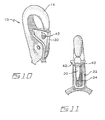
- Figures 12 and 12a illustrate the use of in 40 on an embodiment having a swivel mounted eye.
- gate 30 may alternatively have integral laterally projecting wings 42 so as to provide a further example of a grip enhancing member form of actuating protrusion to facilitate rotation of gate 30 to its open position.
- the wings or other actuating protrusions may be rigid, or may be of, or include, resilient material mounted to the sides of the gate.
- Figures 13a-13d illustrate the use of wings 42 on an embodiment having a swivel mounted eye.
Landscapes
- Engineering & Computer Science (AREA)
- General Engineering & Computer Science (AREA)
- Mechanical Engineering (AREA)
- Hooks, Suction Cups, And Attachment By Adhesive Means (AREA)
- Orthopedics, Nursing, And Contraception (AREA)
- Walking Sticks, Umbrellas, And Fans (AREA)
- Passenger Equipment (AREA)
- Buckles (AREA)
- Massaging Devices (AREA)
Claims (8)
- Karabinerverbinder (10), umfassend:ein starres längliches Element mit einem Mittelteil (12),einen Haken (14) mit einem Schaft (14a) und einem gekrümmten distalen Ende (18), wobei sich der Haken (14) aus einem ersten Ende des Mittelteils (12) erstreckt, so dass ein Hakenfreiraum (16) zwischen dem Schaft (14a) und dem distalen Ende (18) begrenzt wird, und eine Öffnung (20) zwischen dem distalen Ende des Hakens und dem ersten Ende des Mittelteils, wobei sich ein Auge (24) aus einem zum ersten Ende allgemein entgegengesetzten zweiten Ende des Mittelteils erstreckt,ein starres Schnapperelement (30), das schwenkbar am Mittelteil (12) angebracht ist und im Wesentlichen in einer den Haken enthaltenen Ebene liegt, so dass es zwischen einer geschlossenen Stellung, in der eine Stirnfläche (30a) des Schnapperelements die Öffnung blockiert und den Hakenfreiraum verschließt, und einer offenen Stellung verschwenkbar ist, in der das Schnapperelement weg vom Haken von der Öffnung nach außen geschwenkt worden ist, so dass die Öffnung freigegeben wird, wobei ein Zugang zum Hakenfreiraum ermöglicht wird,mindestens ein vom Schnapperelement nach außen ragendes Griffverbesserungselement (36),dadurch gekennzeichnet, dass sich die Stirnfläche von der Öffnung bis zum Schaft des Hakens erstreckt, allgemein orthogonal in Bezug zum Schaft, so dass sie sich über den Hakenfreiraum erstreckt, so dass in der geschlossenen Stellung ein gegen die Stirnfläche (30a) drückender Gegenstand im Hakenfreiraum das Schnapperelement nicht entgegen der Rückstellspannkraft eines elastischen Vorspannmittels (34), das im Mittelteil angebracht ist, um das Schnapperelement elastisch aus der offenen Stellung in die geschlossene Stellung vorzuspannen, in die offene Stellung drücken wird.
- verbinder nach Anspruch 1, bei dem das Griffverbesserungselement ein starrer Hebel (36) ist, der sich in der besagten Ebene vom Schnapper nach außen zu erstreckt, wobei er in Bezug zu der Stirnfläche des Schnappers (30) entgegengesetzt angeordnet ist, so dass er sich einseitig eingespannt vom Schnapper und dem distalen Ende (18) des Hakens (14) nach außen zu erstreckt, wenn sich der Schnapper in der geschlossenen Stellung befindet.
- Verbinder nach Anspruch 2, bei dem der Hebel (36) nasenförmig ist.
- Verbinder nach Anspruch 3, weiter umfassend Griffverbesserungsriefen (36a), die auf einer äußeren Oberfläche des Hebels (36) ausgebildet sind.
- Verbinder nach Anspruch 1, bei dem das Griffverbesserungselement ein Element ist, das sich von der besagten Ebene aus allgemein orthogonal nach außen aus dem Schnapper (30) erstreckt.
- Verbinder nach Anspruch 5, bei dem das Griffverbesserungselement ein starrer Bolzen (40) ist, der sich durch den Schnapper erstreckt, so dass entgegengesetzte Enden des Bolzens gleichermaßen aus entgegengesetzten Seiten des Schnappers ragen.
- Verbinder nach Anspruch 5, bei dem das Griffverbesserungselement mindestens einen flügelförmigen Vorsprung (42) einschließt, der sich aus Seiten des Schnappers erstreckt.
- Verbinder nach Anspruch 7, bei dem der mindestens eine flügelförmige Vorsprung (42) ein Paar von flügelförmigen Vorsprüngen ist, die in entgegengesetzt angeordneter Anordnung auf entgegengesetzten Seiten des Schnappers angebracht sind.
Applications Claiming Priority (2)
| Application Number | Priority Date | Filing Date | Title |
|---|---|---|---|
| CA002434877A CA2434877C (en) | 2003-07-03 | 2003-07-03 | Bullsnap |
| CA2434877 | 2003-07-03 |
Publications (2)
| Publication Number | Publication Date |
|---|---|
| EP1493710A1 EP1493710A1 (de) | 2005-01-05 |
| EP1493710B1 true EP1493710B1 (de) | 2007-07-11 |
Family
ID=33426247
Family Applications (1)
| Application Number | Title | Priority Date | Filing Date |
|---|---|---|---|
| EP03078173A Expired - Lifetime EP1493710B1 (de) | 2003-07-03 | 2003-10-07 | Karabinerhaken |
Country Status (5)
| Country | Link |
|---|---|
| EP (1) | EP1493710B1 (de) |
| AT (1) | ATE366708T1 (de) |
| AU (1) | AU2003252633A1 (de) |
| CA (1) | CA2434877C (de) |
| DE (1) | DE60314856T2 (de) |
Families Citing this family (1)
| Publication number | Priority date | Publication date | Assignee | Title |
|---|---|---|---|---|
| GB2594990A (en) * | 2020-05-15 | 2021-11-17 | Flintstone Tech Limited | Improvements in or relating to chain connection |
Family Cites Families (6)
| Publication number | Priority date | Publication date | Assignee | Title |
|---|---|---|---|---|
| US1626866A (en) * | 1926-10-30 | 1927-05-03 | Robert E Neilson | Safety hook |
| US2927358A (en) * | 1957-05-21 | 1960-03-08 | Ralph A Ratcliff | Hoist hook having spring urged gate latching means |
| US3194598A (en) * | 1963-09-18 | 1965-07-13 | Martin N Goldfuss | Helicopter rescue hook |
| US3798716A (en) * | 1972-04-26 | 1974-03-26 | E Klein | Snap fastening device |
| US4977647A (en) * | 1989-10-27 | 1990-12-18 | D.B. Industries, Inc. | Double locking snap hook |
| DE20005131U1 (de) * | 2000-03-20 | 2000-07-27 | Zinonidis, Evangelos, 58300 Wetter | Armfalle zur Sicherung von Lasthaken |
-
2003
- 2003-07-03 CA CA002434877A patent/CA2434877C/en not_active Expired - Lifetime
- 2003-10-02 AU AU2003252633A patent/AU2003252633A1/en not_active Abandoned
- 2003-10-07 EP EP03078173A patent/EP1493710B1/de not_active Expired - Lifetime
- 2003-10-07 AT AT03078173T patent/ATE366708T1/de not_active IP Right Cessation
- 2003-10-07 DE DE60314856T patent/DE60314856T2/de not_active Expired - Lifetime
Also Published As
| Publication number | Publication date |
|---|---|
| DE60314856T2 (de) | 2007-12-20 |
| DE60314856D1 (de) | 2007-08-23 |
| ATE366708T1 (de) | 2007-08-15 |
| CA2434877A1 (en) | 2005-01-03 |
| CA2434877C (en) | 2009-10-27 |
| EP1493710A1 (de) | 2005-01-05 |
| AU2003252633A1 (en) | 2005-01-20 |
Similar Documents
| Publication | Publication Date | Title |
|---|---|---|
| US6925690B2 (en) | Bullsnap | |
| US6223372B1 (en) | Combination carabiner and tool device | |
| EP0961578B1 (de) | Werkzeug zum anbringen von ohrmarken | |
| US20030070299A1 (en) | Folding knife | |
| US20120159789A9 (en) | Folding knife | |
| US7040201B2 (en) | Quick adjusting pliers | |
| US20080083302A1 (en) | Jar opener | |
| US7089832B2 (en) | Quick adjusting pliers | |
| US2885814A (en) | Hook baiter | |
| EP3450070A1 (de) | Handhaltbarer rohrschneider mit einem sicherer und verfahren zum schneiden eines rohrs | |
| CA2408897C (fr) | Dispositif de securite pour attache rapide destinee a fixer un outil a l'extremite du bras d'un chargeur ou analogue | |
| EP1970105A1 (de) | Handgriff für einen Skistock | |
| CA2434877C (en) | Bullsnap | |
| CA2569808A1 (en) | Snap hook | |
| US4598492A (en) | Fish gaff | |
| US20040255437A1 (en) | Snap-hook tether | |
| JP2008211986A (ja) | 挟持具 | |
| RU2679816C2 (ru) | Инструмент для ювелирных изделий | |
| US3061835A (en) | Nail holder and set device | |
| JP2014113354A (ja) | 魚挟み具 | |
| JP5487281B2 (ja) | 魚掴み器 | |
| EP4150223B1 (de) | Befestigungselement | |
| US4118883A (en) | Fishhook and releasing tool therefor | |
| US7013594B1 (en) | Pivoting split shot attachment and removal tool | |
| US7010880B1 (en) | Split shot attachment and removal tool |
Legal Events
| Date | Code | Title | Description |
|---|---|---|---|
| PUAI | Public reference made under article 153(3) epc to a published international application that has entered the european phase |
Free format text: ORIGINAL CODE: 0009012 |
|
| AK | Designated contracting states |
Kind code of ref document: A1 Designated state(s): AT BE BG CH CY CZ DE DK EE ES FI FR GB GR HU IE IT LI LU MC NL PT RO SE SI SK TR |
|
| AX | Request for extension of the european patent |
Extension state: AL LT LV MK |
|
| 17P | Request for examination filed |
Effective date: 20050519 |
|
| AKX | Designation fees paid |
Designated state(s): AT BE BG CH CY CZ DE DK EE ES FI FR GB GR HU IE IT LI LU MC NL PT RO SE SI SK TR |
|
| 17Q | First examination report despatched |
Effective date: 20060807 |
|
| GRAP | Despatch of communication of intention to grant a patent |
Free format text: ORIGINAL CODE: EPIDOSNIGR1 |
|
| GRAS | Grant fee paid |
Free format text: ORIGINAL CODE: EPIDOSNIGR3 |
|
| GRAA | (expected) grant |
Free format text: ORIGINAL CODE: 0009210 |
|
| AK | Designated contracting states |
Kind code of ref document: B1 Designated state(s): AT BE BG CH CY CZ DE DK EE ES FI FR GB GR HU IE IT LI LU MC NL PT RO SE SI SK TR |
|
| REG | Reference to a national code |
Ref country code: GB Ref legal event code: FG4D |
|
| REG | Reference to a national code |
Ref country code: CH Ref legal event code: EP |
|
| REF | Corresponds to: |
Ref document number: 60314856 Country of ref document: DE Date of ref document: 20070823 Kind code of ref document: P |
|
| REG | Reference to a national code |
Ref country code: IE Ref legal event code: FG4D |
|
| PG25 | Lapsed in a contracting state [announced via postgrant information from national office to epo] |
Ref country code: NL Free format text: LAPSE BECAUSE OF FAILURE TO SUBMIT A TRANSLATION OF THE DESCRIPTION OR TO PAY THE FEE WITHIN THE PRESCRIBED TIME-LIMIT Effective date: 20070711 Ref country code: BG Free format text: LAPSE BECAUSE OF FAILURE TO SUBMIT A TRANSLATION OF THE DESCRIPTION OR TO PAY THE FEE WITHIN THE PRESCRIBED TIME-LIMIT Effective date: 20071011 Ref country code: PT Free format text: LAPSE BECAUSE OF FAILURE TO SUBMIT A TRANSLATION OF THE DESCRIPTION OR TO PAY THE FEE WITHIN THE PRESCRIBED TIME-LIMIT Effective date: 20071211 Ref country code: FI Free format text: LAPSE BECAUSE OF FAILURE TO SUBMIT A TRANSLATION OF THE DESCRIPTION OR TO PAY THE FEE WITHIN THE PRESCRIBED TIME-LIMIT Effective date: 20070711 Ref country code: ES Free format text: LAPSE BECAUSE OF FAILURE TO SUBMIT A TRANSLATION OF THE DESCRIPTION OR TO PAY THE FEE WITHIN THE PRESCRIBED TIME-LIMIT Effective date: 20071022 |
|
| REG | Reference to a national code |
Ref country code: CH Ref legal event code: PL |
|
| NLV1 | Nl: lapsed or annulled due to failure to fulfill the requirements of art. 29p and 29m of the patents act | ||
| PG25 | Lapsed in a contracting state [announced via postgrant information from national office to epo] |
Ref country code: LI Free format text: LAPSE BECAUSE OF FAILURE TO SUBMIT A TRANSLATION OF THE DESCRIPTION OR TO PAY THE FEE WITHIN THE PRESCRIBED TIME-LIMIT Effective date: 20070711 Ref country code: CH Free format text: LAPSE BECAUSE OF FAILURE TO SUBMIT A TRANSLATION OF THE DESCRIPTION OR TO PAY THE FEE WITHIN THE PRESCRIBED TIME-LIMIT Effective date: 20070711 Ref country code: AT Free format text: LAPSE BECAUSE OF FAILURE TO SUBMIT A TRANSLATION OF THE DESCRIPTION OR TO PAY THE FEE WITHIN THE PRESCRIBED TIME-LIMIT Effective date: 20070711 |
|
| EN | Fr: translation not filed | ||
| PG25 | Lapsed in a contracting state [announced via postgrant information from national office to epo] |
Ref country code: BE Free format text: LAPSE BECAUSE OF FAILURE TO SUBMIT A TRANSLATION OF THE DESCRIPTION OR TO PAY THE FEE WITHIN THE PRESCRIBED TIME-LIMIT Effective date: 20070711 |
|
| PG25 | Lapsed in a contracting state [announced via postgrant information from national office to epo] |
Ref country code: GR Free format text: LAPSE BECAUSE OF FAILURE TO SUBMIT A TRANSLATION OF THE DESCRIPTION OR TO PAY THE FEE WITHIN THE PRESCRIBED TIME-LIMIT Effective date: 20071012 Ref country code: DK Free format text: LAPSE BECAUSE OF FAILURE TO SUBMIT A TRANSLATION OF THE DESCRIPTION OR TO PAY THE FEE WITHIN THE PRESCRIBED TIME-LIMIT Effective date: 20070711 |
|
| PLBE | No opposition filed within time limit |
Free format text: ORIGINAL CODE: 0009261 |
|
| STAA | Information on the status of an ep patent application or granted ep patent |
Free format text: STATUS: NO OPPOSITION FILED WITHIN TIME LIMIT |
|
| PG25 | Lapsed in a contracting state [announced via postgrant information from national office to epo] |
Ref country code: CZ Free format text: LAPSE BECAUSE OF FAILURE TO SUBMIT A TRANSLATION OF THE DESCRIPTION OR TO PAY THE FEE WITHIN THE PRESCRIBED TIME-LIMIT Effective date: 20070711 Ref country code: MC Free format text: LAPSE BECAUSE OF NON-PAYMENT OF DUE FEES Effective date: 20071031 Ref country code: SK Free format text: LAPSE BECAUSE OF FAILURE TO SUBMIT A TRANSLATION OF THE DESCRIPTION OR TO PAY THE FEE WITHIN THE PRESCRIBED TIME-LIMIT Effective date: 20070711 |
|
| 26N | No opposition filed |
Effective date: 20080414 |
|
| PG25 | Lapsed in a contracting state [announced via postgrant information from national office to epo] |
Ref country code: SE Free format text: LAPSE BECAUSE OF FAILURE TO SUBMIT A TRANSLATION OF THE DESCRIPTION OR TO PAY THE FEE WITHIN THE PRESCRIBED TIME-LIMIT Effective date: 20071011 Ref country code: RO Free format text: LAPSE BECAUSE OF FAILURE TO SUBMIT A TRANSLATION OF THE DESCRIPTION OR TO PAY THE FEE WITHIN THE PRESCRIBED TIME-LIMIT Effective date: 20070711 |
|
| PG25 | Lapsed in a contracting state [announced via postgrant information from national office to epo] |
Ref country code: FR Free format text: LAPSE BECAUSE OF FAILURE TO SUBMIT A TRANSLATION OF THE DESCRIPTION OR TO PAY THE FEE WITHIN THE PRESCRIBED TIME-LIMIT Effective date: 20080307 |
|
| PG25 | Lapsed in a contracting state [announced via postgrant information from national office to epo] |
Ref country code: IE Free format text: LAPSE BECAUSE OF NON-PAYMENT OF DUE FEES Effective date: 20071008 |
|
| PG25 | Lapsed in a contracting state [announced via postgrant information from national office to epo] |
Ref country code: EE Free format text: LAPSE BECAUSE OF FAILURE TO SUBMIT A TRANSLATION OF THE DESCRIPTION OR TO PAY THE FEE WITHIN THE PRESCRIBED TIME-LIMIT Effective date: 20070711 |
|
| PG25 | Lapsed in a contracting state [announced via postgrant information from national office to epo] |
Ref country code: SI Free format text: LAPSE BECAUSE OF FAILURE TO SUBMIT A TRANSLATION OF THE DESCRIPTION OR TO PAY THE FEE WITHIN THE PRESCRIBED TIME-LIMIT Effective date: 20070711 |
|
| PG25 | Lapsed in a contracting state [announced via postgrant information from national office to epo] |
Ref country code: CY Free format text: LAPSE BECAUSE OF FAILURE TO SUBMIT A TRANSLATION OF THE DESCRIPTION OR TO PAY THE FEE WITHIN THE PRESCRIBED TIME-LIMIT Effective date: 20070711 |
|
| PG25 | Lapsed in a contracting state [announced via postgrant information from national office to epo] |
Ref country code: LU Free format text: LAPSE BECAUSE OF NON-PAYMENT OF DUE FEES Effective date: 20071007 |
|
| PG25 | Lapsed in a contracting state [announced via postgrant information from national office to epo] |
Ref country code: HU Free format text: LAPSE BECAUSE OF FAILURE TO SUBMIT A TRANSLATION OF THE DESCRIPTION OR TO PAY THE FEE WITHIN THE PRESCRIBED TIME-LIMIT Effective date: 20080112 Ref country code: TR Free format text: LAPSE BECAUSE OF FAILURE TO SUBMIT A TRANSLATION OF THE DESCRIPTION OR TO PAY THE FEE WITHIN THE PRESCRIBED TIME-LIMIT Effective date: 20070711 |
|
| PG25 | Lapsed in a contracting state [announced via postgrant information from national office to epo] |
Ref country code: IT Free format text: LAPSE BECAUSE OF NON-PAYMENT OF DUE FEES Effective date: 20071031 |
|
| PGFP | Annual fee paid to national office [announced via postgrant information from national office to epo] |
Ref country code: GB Payment date: 20220901 Year of fee payment: 20 |
|
| PGFP | Annual fee paid to national office [announced via postgrant information from national office to epo] |
Ref country code: DE Payment date: 20220831 Year of fee payment: 20 |
|
| REG | Reference to a national code |
Ref country code: DE Ref legal event code: R071 Ref document number: 60314856 Country of ref document: DE |
|
| REG | Reference to a national code |
Ref country code: GB Ref legal event code: PE20 Expiry date: 20231006 |
|
| PG25 | Lapsed in a contracting state [announced via postgrant information from national office to epo] |
Ref country code: GB Free format text: LAPSE BECAUSE OF EXPIRATION OF PROTECTION Effective date: 20231006 |
|
| PG25 | Lapsed in a contracting state [announced via postgrant information from national office to epo] |
Ref country code: GB Free format text: LAPSE BECAUSE OF EXPIRATION OF PROTECTION Effective date: 20231006 |